EP0068053B1 - Ultraschallsonde - Google Patents
Ultraschallsonde Download PDFInfo
- Publication number
- EP0068053B1 EP0068053B1 EP81302953A EP81302953A EP0068053B1 EP 0068053 B1 EP0068053 B1 EP 0068053B1 EP 81302953 A EP81302953 A EP 81302953A EP 81302953 A EP81302953 A EP 81302953A EP 0068053 B1 EP0068053 B1 EP 0068053B1
- Authority
- EP
- European Patent Office
- Prior art keywords
- receivers
- receiver
- transmitter
- ultrasonic
- echo signal
- Prior art date
- Legal status (The legal status is an assumption and is not a legal conclusion. Google has not performed a legal analysis and makes no representation as to the accuracy of the status listed.)
- Expired
Links
- 239000000523 sample Substances 0.000 title claims description 32
- 238000002592 echocardiography Methods 0.000 claims description 24
- 238000011835 investigation Methods 0.000 claims description 7
- 238000002604 ultrasonography Methods 0.000 claims description 5
- 238000003384 imaging method Methods 0.000 description 13
- 238000000034 method Methods 0.000 description 7
- 238000012545 processing Methods 0.000 description 5
- 230000009466 transformation Effects 0.000 description 5
- 230000002596 correlated effect Effects 0.000 description 3
- 230000000875 corresponding effect Effects 0.000 description 3
- 230000002238 attenuated effect Effects 0.000 description 2
- 230000005540 biological transmission Effects 0.000 description 2
- 238000010276 construction Methods 0.000 description 2
- 238000013016 damping Methods 0.000 description 2
- 230000000694 effects Effects 0.000 description 2
- 238000002347 injection Methods 0.000 description 2
- 239000007924 injection Substances 0.000 description 2
- 239000000463 material Substances 0.000 description 2
- 230000001276 controlling effect Effects 0.000 description 1
- 230000001934 delay Effects 0.000 description 1
- 238000013461 design Methods 0.000 description 1
- 238000011161 development Methods 0.000 description 1
- 238000003745 diagnosis Methods 0.000 description 1
- 238000010586 diagram Methods 0.000 description 1
- 230000009365 direct transmission Effects 0.000 description 1
- 239000003814 drug Substances 0.000 description 1
- 230000008030 elimination Effects 0.000 description 1
- 238000003379 elimination reaction Methods 0.000 description 1
- 238000004806 packaging method and process Methods 0.000 description 1
- 229920003023 plastic Polymers 0.000 description 1
- 239000004033 plastic Substances 0.000 description 1
- 238000011160 research Methods 0.000 description 1
- 238000000844 transformation Methods 0.000 description 1
Images


Classifications
-
- G—PHYSICS
- G01—MEASURING; TESTING
- G01S—RADIO DIRECTION-FINDING; RADIO NAVIGATION; DETERMINING DISTANCE OR VELOCITY BY USE OF RADIO WAVES; LOCATING OR PRESENCE-DETECTING BY USE OF THE REFLECTION OR RERADIATION OF RADIO WAVES; ANALOGOUS ARRANGEMENTS USING OTHER WAVES
- G01S7/00—Details of systems according to groups G01S13/00, G01S15/00, G01S17/00
- G01S7/52—Details of systems according to groups G01S13/00, G01S15/00, G01S17/00 of systems according to group G01S15/00
- G01S7/52017—Details of systems according to groups G01S13/00, G01S15/00, G01S17/00 of systems according to group G01S15/00 particularly adapted to short-range imaging
- G01S7/52053—Display arrangements
- G01S7/52057—Cathode ray tube displays
- G01S7/5206—Two-dimensional coordinated display of distance and direction; B-scan display
-
- B—PERFORMING OPERATIONS; TRANSPORTING
- B06—GENERATING OR TRANSMITTING MECHANICAL VIBRATIONS IN GENERAL
- B06B—METHODS OR APPARATUS FOR GENERATING OR TRANSMITTING MECHANICAL VIBRATIONS OF INFRASONIC, SONIC, OR ULTRASONIC FREQUENCY, e.g. FOR PERFORMING MECHANICAL WORK IN GENERAL
- B06B1/00—Methods or apparatus for generating mechanical vibrations of infrasonic, sonic, or ultrasonic frequency
- B06B1/02—Methods or apparatus for generating mechanical vibrations of infrasonic, sonic, or ultrasonic frequency making use of electrical energy
- B06B1/06—Methods or apparatus for generating mechanical vibrations of infrasonic, sonic, or ultrasonic frequency making use of electrical energy operating with piezoelectric effect or with electrostriction
- B06B1/0607—Methods or apparatus for generating mechanical vibrations of infrasonic, sonic, or ultrasonic frequency making use of electrical energy operating with piezoelectric effect or with electrostriction using multiple elements
- B06B1/0622—Methods or apparatus for generating mechanical vibrations of infrasonic, sonic, or ultrasonic frequency making use of electrical energy operating with piezoelectric effect or with electrostriction using multiple elements on one surface
-
- G—PHYSICS
- G01—MEASURING; TESTING
- G01S—RADIO DIRECTION-FINDING; RADIO NAVIGATION; DETERMINING DISTANCE OR VELOCITY BY USE OF RADIO WAVES; LOCATING OR PRESENCE-DETECTING BY USE OF THE REFLECTION OR RERADIATION OF RADIO WAVES; ANALOGOUS ARRANGEMENTS USING OTHER WAVES
- G01S15/00—Systems using the reflection or reradiation of acoustic waves, e.g. sonar systems
- G01S15/88—Sonar systems specially adapted for specific applications
- G01S15/89—Sonar systems specially adapted for specific applications for mapping or imaging
- G01S15/8906—Short-range imaging systems; Acoustic microscope systems using pulse-echo techniques
- G01S15/8909—Short-range imaging systems; Acoustic microscope systems using pulse-echo techniques using a static transducer configuration
- G01S15/8913—Short-range imaging systems; Acoustic microscope systems using pulse-echo techniques using a static transducer configuration using separate transducers for transmission and reception
-
- G—PHYSICS
- G01—MEASURING; TESTING
- G01S—RADIO DIRECTION-FINDING; RADIO NAVIGATION; DETERMINING DISTANCE OR VELOCITY BY USE OF RADIO WAVES; LOCATING OR PRESENCE-DETECTING BY USE OF THE REFLECTION OR RERADIATION OF RADIO WAVES; ANALOGOUS ARRANGEMENTS USING OTHER WAVES
- G01S15/00—Systems using the reflection or reradiation of acoustic waves, e.g. sonar systems
- G01S15/88—Sonar systems specially adapted for specific applications
- G01S15/89—Sonar systems specially adapted for specific applications for mapping or imaging
- G01S15/8906—Short-range imaging systems; Acoustic microscope systems using pulse-echo techniques
- G01S15/8909—Short-range imaging systems; Acoustic microscope systems using pulse-echo techniques using a static transducer configuration
- G01S15/8915—Short-range imaging systems; Acoustic microscope systems using pulse-echo techniques using a static transducer configuration using a transducer array
- G01S15/8918—Short-range imaging systems; Acoustic microscope systems using pulse-echo techniques using a static transducer configuration using a transducer array the array being linear
Definitions
- the invention relates to an ultrasonic probe for injecting ultrasonic pulses into a body under investigation, for detecting resulting echo signals from within the body and for generating echo signal waveforms representing the echo signals detected.
- ultrasonic probe incorporating an array of ultrasonic transducers, which in use is placed in contact with a patient's body and selected transducers energised to transmit ultrasound into the body.
- the ultrasound is reflected from acoustic impedance discontinuities within the body and the echoes are detected and converted by the transducers to electric echo signals.
- the time delays between the transmission of each ultrasonic pulse into the body and receipt of the echoes of that pulse are proportional to the distances from the various transducers to the discontinuities within the body producing the echoes.
- a plurality of transducers are used in a controlled manner to transmit and receive echoes of ultrasound and the resulting electric echo signals processed to construct a cross-sectional image of the body which is displayed on a cathode ray tube.
- the number and size of the transducer elements in the array are determined having regard to the design requirements needed for the specific application.
- the pattern of energisation is selected to provide a beam of required characteristics for the application.
- a linear array of transducers may be used, the angle of incidence of the beam being determined by the phase relationship between the energised elements in the array.
- the intensity of sound may be enhanced in a selected direction from the centre of a linear array of transducers by phasing the transmission times from individual transmitting transducers.
- the received echoes are subsequently electronically focussed by reverse phasing of the received signals. This method suffers inevitably from random echoes caused by 'sidelobes' of the transmitted.soundwaves.
- the transducers in a linear array may be energised simultaneously, a group at a time, to achieve homogeneity of the wave and the received echoes routed through selected delay lines, thus achieving a measure of electronic focussing.
- This method suffers from echo artefacts due to the large area being insonified, and by the fact that delay lines provide only one part of the time transformation necessary for exact focussing.
- an acoustic imaging technique is used to cross- correlate the outputs of two or more receivers whereby, it is claimed, the time of occurrence of the resulting output pulse is proportional to the distance from the scatterer to the beam axis of the transmitter and the strength of this pulse increases as the acoustic strength of the scatterer increases.
- the technique used appears to be capable of determining the direction of a scatterer but does not appear to be useful for determining distance of the scatterer.
- the ultrasonic probe subject of this invention differs from the prior art in that a pair of pulse echo receivers are provided for one pulse transmitter.
- the two receivers in each pair lie in a plane at right angles to the pulse propagation axis of the transmitter and equidistant therefrom.
- the outputs from the two receivers in each receiver pair are connected to means which combine the two echo signal waveforms from the two receivers so that the time coincident components of the two waveforms are emphasised. This has the considerably advantageous effect of focussing the probe in the longitudinal plane of symmetry of the probe.
- the transmitters are circular in cross-section and of large diameter in comparison to the receivers which are also circular in cross-section.
- the receivers are conveniently located in the gaps between adjacent transmitters producing an overall compact package.
- the circuits for selecting the transmitters and the circuits for processing the echo signal waveforms from the receivers are conveniently provided on each side of a single circuit board.
- the complete probe is contained in a hand-held container.
- a probe shown in Figure 1 consists of a linear array of ultrasonic transducers each consisting of a pulse transmitter for injecting a pulse into a body under investigation and a pair of echo receivers for detecting echoes of pulses reflected from within the body.
- the probe 1 consists of a row of piezoelectric transmitters T1 to TN positioned between two parallel rows of piezoelectric receivers RA1 to RA(N + 1) and RB1 to RB(N + 1) respectively.
- the transmitters T are constructed with a relatively larger diameter than that of the receivers RA, RB in order to generate when energised a fairly directional sound wave travelling along a substantially parallel beam.
- the smaller receivers are conveniently located on each side of the array one in each of the two available gaps between adjacent transmitters.
- Correspondingly positioned receivers in the two rows are regarded as constituting pairs of receivers (RA2, RB2) (RA3, RB3) etc.
- a further pair of receivers is provided at each end of the array thereby making maximum use of the available space.
- each receiver RA and RB is connected to a respective differential amplifier 2A and 2B.
- the outputs from the two amplifiers are connected as inputs to analogue multiplier 3.
- the multiplication of the individual echo signals received by the two receivers emphasises the time coincident components of the signals of the pair of receivers. Since each pair of receivers is symmetrically positioned on each side of the row of transmitters, the output signals received from the multipliers represent echoes received of reflections only from objects lying in the longitudinal plane of symmetry 4 ( Figure 1) of the linear array of transducers.
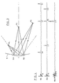
- FIG. 3 shows a single transmitter T and a receiver pair RA, RB in contact with a body 5 under investigation.
- a pulse directed into the body in the direction of transmitter longitudinal axis 6 is reflected from discontinuities P1, P2 and P3 within the body. Only discontinuity P2 lies on the longitudinal axis.
- the incident sound is shown diverging widely so as to produce echoes from widely spaced points P1 and P3.
- the transmitter face is contoured in a known manner such that the incident beam is substantially parallel.
- the resulting echo signal waveform generated by the receivers RA and RB and amplifiers 2A and 2B from echoes received from the reflecting points P1, P2 and P3 are shown respectively in waveforms (a) and (b) of Figure 4 as corresponding echo signals E1, E2 and E3.
- Each waveform include initial noise N caused by direct transmission of the injected pulse into the receivers. This noise is attenuated as much as possible by damping material between receivers and transmitters. Detailed description of the physical construction of the probe will be given hereinafter with reference to Figure 6.
- the correlated echo signal waveform output from the associated multiplier 3 to which the waveforms (a) and (b) are applied as inputs is shown in waveform (c) of Figure 4.
- the multiplication of the individual signal components E1 and E3 on one waveform by near-zero amplitude signals on the other waveform has resulted in their elimination.
- the multiplication of the time coincident echo signal components E2 has resulted in a large amplitude signal component E2'.
- the echo signal content from multiplier 3 therefore represents only echoes received from reflecting entities within the body located along the longitudinal axis 6 of the transmitter. It is seen therefore that the effect of this correlation process on all transducer element outputs is to focus the echoes received by the probe in the longitudinal plane of symmetry, or scan plate 4 as it will hereinafter be referred to, of the probe.
- the ultrasonic imaging apparatus described therein utilises a probe having 23 transmitters and 24 receiver pairs.
- the transducers are supported closely adjacent to one another and are energised successively in turn to inject a continuous sequential cycle of ultrasonic pulses, one after the other, into the body under investigation.
- a complete section of the body defined by the scan plane of the transmitters is repetitively and continuously insonified.
- Focussing of the echo information along selected focus lines in the scan plane itself is achieved as described in the aforesaid application by processing the echo signal waveforms received by a selected group of receiver pairs following injection of each individual pulse.
- the processing of the echo signal waveforms is calculated to compensate for the different propagation times of the echoes from the different reflecting points in the body along selected focus lines, and involves performing time transformations on the correlated echo signal waveforms generated by those receiver pairs in the group associated with the energised transmitter which are off-set from the currently selected focus line. Following the time transformation, all signal waveforms from the group of receivers are themselves correlated by, for example multiplication, to generate a single echo signal waveform containing individual echo signals representing echoes from discontinuities within the body along the currently selected focus line.
- An important feature of the invention described in the aforesaid application is that by modifying the time transformation process, several unique scan lines of an image may be created from the echo information derived from each individual pulse injected into the body. Accordingly the process is repeated, changing the time transformation process as required, to generate echo information for a plurality of equally spaced focus lines for each pulse injected by each transmitter in turn..As each new transmitter is selected, so a group of receiver pairs is identified to generate echo information for processing.
- each echo signal waveform representing the echoes from each focus line is used to modulate the intensity of a CRT beam which is scannin ⁇ in synchronism with the ultrasonic imaging apparatus to build up a complete cross-sectional image of the internal structure with one CRT scan line for each focus line across the insonified section of the scan plane.
- Probe selection circuits are therefore required to respond to control signals supplied from the user imaging apparatus to step through the transmitters in the required sequence; select the group of receiver pairs associated with each transmitter taken in turn; correlate the signals from the two receivers in each receiver pair to focus the echoes in the scan plane; and supply the focussed echo signals as output to the user imaging apparatus.
- the circuits and their connections are shown schematically in Figure 5.
- an ultrasonic probe 1 consisting of twenty-three transmitters T1 to T23 arranged in a row, positioned between two parallel rows of twenty-four receivers arranged in pairs RA1, RB1, to RA24, RB24.
- Each transmitter is individually connected to a count decoder unit 7 which operates in response to an increment transmitter/receiver clock signal on input terminal 9, and fire transmitter signal on input terminal 8 to connect each transmitter in turn in a continuous sequence to a voltage supply (e.g. 50 volts) applied to terminal 10.
- a voltage supply e.g. 50 volts
- receiver pairs RA1, RB1; RA2, RB2; and RA3, RB3 are associated with transmitter T1, receiver pairs RA2, RB2; RA3, RB3; and RA4, RB4 with transmitter T2 and so on stepping through the array to the final groups RA22, RB22; RA23, RB23; and RA24, RB24 associated with transmitters T22 and T23.
- Each receiver in a group of receiver pairs is connected to one of a number of associated individual receiver select registers which operate under control of a decoder register to gate the individual echo signal waveforms generated by the receivers in a selected group through to its output.
- Figure 5 has been simplified to show only selection circuits for one receiver of each receiver pair, it being understood that selection of the other receiver is performed in an identical manner.
- receivers RB1, RB4 ... RB22 are connected as input to receiver select register 11.1; the outputs from receivers RB2 i RB5 ... RB23 are connected as inputs to receiver select register 11.2; and the outputs from receivers RB3, RB6 ... RB24 are connected as inputs to receiver select register 11.3.
- the selection of the receivers in each group is by means of decoder 12 in response to input data supplied over 9-bit bus 13 from the using imaging apparatus.
- the information supplied over bus 13 is decoded and supplied as separate 3-bit inputs to the three receiver select registers 11.1, 11.2 and 11.3 to gate through the echo signal waveforms from the associated receivers in the required group.
- the input data supplied to decoder 12 identifying the next group of registers to be selected is loaded into the decoder on occurrence of a set select signal from the user imaging apparatus via input terminal 14 and the decoded information gated to the three receiver select registers on occurrence of the transmitter/receiver clock signal from terminal 9.
- the decoder can be loaded with the new data as soon as the echo information from the current group of receivers has been utilised by the user apparatus.
- each receiver select register 11.1, 11.2, 11.3 is supplied to a respective amplifier 2B.1, 2B.2, 2B.3 and the outputs from the amplifiers are supplied as one input to an associated one of three multipliers 3.1, 3.2, 3.3.
- the other inputs to the multipliers are supplied from corresponding amplifiers 2A.1, 2A.2, 2A.3 associated with the receivers forming the other half of the receiver pairs in the group.
- the output from multiplier 3.1, 3.2, 3.3 are supplied via amplifiers 15.1, 15.2 and 15.3 respectively to output terminals 16.1, 16.2, 16.3. Since the echo signals become progressively attenuated by the body tissue the greater the distances they have to travel, the gain of the multipliers is increased with time to compensate.
- a varying voltage gain control signal is supplied currently to all three multipliers by the-user imaging apparatus via input terminal 17.
- selection of the next successive transmitter is accompanied by the simultaneous identification and selection of the associated receiver pair grouping (RA1, RB1; RA2, RB2; RA3, RB3).
- the echo signals of the pulse injected by the transmitter are detected by the selected receiver pair group and are gated through the two sets of registers (one set 11.1, 11.2,11.3 shown) amplified by amplifier 2A1.2B1; 2A2, 2B2; 2A3, 2A3 and the amplified echo signal waveforms from the two receivers in each receiver multiplied together by the associated multipliers 3.1, 3.2, 3.3. Over the period during which the echo signal waveforms are being multiplied together, the gain of the multipliers is being progressively increased to compensate for signal attenuation.
- the output from the multipliers representing those echoes detected by each receiver originating from points with the body in the scan plane defined by the probe are amplified further by amplifiers 15.1, 15.2, 15.3 and supplied as output signals for the user imaging apparatus on terminals 16.1, 16.2, 16.3.
- the practical probe assembly is shown as a hand-held unit in Figure 6.
- the piezoelectric transmitters T1 to T23 and piezoelectric receiver pairs RA1, RB1 ... RA24, RB24 are insulated from each other by a thin layer of damping material (not shown) interleaved therebetween.
- the entire transducer assembly is potted in a plastics block 19 for support.
- Each piezoelectric transducer has two wires for connection to the controlling circuits. In the case of a transmitter, one wire is for connection to the energising voltage supply and the other to ground. The ground connections were excluded from the circuit diagram of Figure 5 for simplicity.
- the echo signals are generated as differential signals on the two wires. Only one output was shown for each receiver in Figure 5 for simplicity. It will be understood that with differential outputs the various amplifiers are in fact differential amplifiers.
- the potted transducer block 19 is supported in a cut-away portion of a circuit card 20.
- An elongated pin connector 21 is supported in the cut-away portion and receives the transducer pins.
- the transmitter and receiver selection circuitry, the amplifiers and multipliers are all supported as individual components and modules (a few shown schematically) and interconnected on the two sides of the card 20.
- the signals required to drive the probe are supplied to signal tabs 8, 9, 10, 18 and bus 13, power inputs for the components to tabs 22 and the three output signals from output tabs 16.1, 16.2, 16.3.
- the entire circuit board and probe assembly is supported for use in a moulded box 23 having an elongated aperture 24 exposing the transmitters and receiver pairs.
- the assembly is supported within the box by a pair of integral moulded rails 25.
Landscapes
- Engineering & Computer Science (AREA)
- Physics & Mathematics (AREA)
- Radar, Positioning & Navigation (AREA)
- Remote Sensing (AREA)
- Acoustics & Sound (AREA)
- Computer Networks & Wireless Communication (AREA)
- General Physics & Mathematics (AREA)
- Mechanical Engineering (AREA)
- Investigating Or Analyzing Materials By The Use Of Ultrasonic Waves (AREA)
- Ultra Sonic Daignosis Equipment (AREA)
- Transducers For Ultrasonic Waves (AREA)
Claims (6)
Priority Applications (4)
| Application Number | Priority Date | Filing Date | Title |
|---|---|---|---|
| EP81302953A EP0068053B2 (de) | 1981-06-29 | 1981-06-29 | Ultraschallsonde |
| DE8181302953T DE3170393D1 (en) | 1981-06-29 | 1981-06-29 | Ultrasonic probe |
| US06/351,077 US4474065A (en) | 1981-06-29 | 1982-02-22 | Ultrasonic probe |
| JP57062654A JPS587232A (ja) | 1981-06-29 | 1982-04-16 | 超音波プロ−ブ |
Applications Claiming Priority (1)
| Application Number | Priority Date | Filing Date | Title |
|---|---|---|---|
| EP81302953A EP0068053B2 (de) | 1981-06-29 | 1981-06-29 | Ultraschallsonde |
Publications (3)
| Publication Number | Publication Date |
|---|---|
| EP0068053A1 EP0068053A1 (de) | 1983-01-05 |
| EP0068053B1 true EP0068053B1 (de) | 1985-05-08 |
| EP0068053B2 EP0068053B2 (de) | 1989-01-04 |
Family
ID=8188339
Family Applications (1)
| Application Number | Title | Priority Date | Filing Date |
|---|---|---|---|
| EP81302953A Expired EP0068053B2 (de) | 1981-06-29 | 1981-06-29 | Ultraschallsonde |
Country Status (4)
| Country | Link |
|---|---|
| US (1) | US4474065A (de) |
| EP (1) | EP0068053B2 (de) |
| JP (1) | JPS587232A (de) |
| DE (1) | DE3170393D1 (de) |
Families Citing this family (2)
| Publication number | Priority date | Publication date | Assignee | Title |
|---|---|---|---|---|
| US7130705B2 (en) * | 2001-01-08 | 2006-10-31 | International Business Machines Corporation | System and method for microphone gain adjust based on speaker orientation |
| US12053325B2 (en) * | 2020-01-06 | 2024-08-06 | California Institute Of Technology | Cross-ray ultrasound tomography (CRUST) methods and systems |
Family Cites Families (9)
| Publication number | Priority date | Publication date | Assignee | Title |
|---|---|---|---|---|
| US3346862A (en) * | 1962-05-24 | 1967-10-10 | Martin Marietta Corp | Correlation detection systems |
| US3683680A (en) * | 1970-02-03 | 1972-08-15 | British Railways Board | Ultrasonic flaw detection apparatus |
| US3889227A (en) * | 1972-09-22 | 1975-06-10 | Tokyo Shibaura Electric Co | Ultrasonic wave receiving apparatus |
| US4011750A (en) * | 1973-06-06 | 1977-03-15 | The Commonwealth Of Australia Care Of The Secretary Department Of Health | Method and apparatus for ultrasonic examination of objects |
| DE2345155B2 (de) * | 1973-09-07 | 1975-09-25 | Krautkraemer Gmbh, 5000 Koeln | Gruppenweise umgetastete, aus zellenförmig und/oder hierzu senkrechten, streifenförmig angeordneten einzelnen Schwingerelementen bestehendes Ultraschall-Prüfkopfsystem zur zerstörungsfreien Werkstoffprüfung |
| DE2643918C3 (de) * | 1976-09-29 | 1986-10-23 | Siemens AG, 1000 Berlin und 8000 München | Gerät zur Ultraschallabtastung |
| US4267584A (en) * | 1977-07-01 | 1981-05-12 | Siemens Gammasonics, Inc. | Permutating analog shift register variable delay system |
| JPS5570759A (en) * | 1978-11-22 | 1980-05-28 | Hitachi Ltd | Ultrasonic wave search unit |
| DE3010210A1 (de) * | 1980-03-17 | 1981-09-24 | Siemens AG, 1000 Berlin und 8000 München | Ultraschall-array |
-
1981
- 1981-06-29 EP EP81302953A patent/EP0068053B2/de not_active Expired
- 1981-06-29 DE DE8181302953T patent/DE3170393D1/de not_active Expired
-
1982
- 1982-02-22 US US06/351,077 patent/US4474065A/en not_active Expired - Lifetime
- 1982-04-16 JP JP57062654A patent/JPS587232A/ja active Pending
Also Published As
| Publication number | Publication date |
|---|---|
| US4474065A (en) | 1984-10-02 |
| DE3170393D1 (en) | 1985-06-13 |
| EP0068053A1 (de) | 1983-01-05 |
| EP0068053B2 (de) | 1989-01-04 |
| JPS587232A (ja) | 1983-01-17 |
Similar Documents
| Publication | Publication Date | Title |
|---|---|---|
| JP4172841B2 (ja) | 超音波イメージング・システム、超音波イメージング・システムを動作させる方法及びマルチプレクサ・マザーボード | |
| US6183419B1 (en) | Multiplexed array transducers with improved far-field performance | |
| Jensen et al. | Ultrasound research scanner for real-time synthetic aperture data acquisition | |
| US4224829A (en) | Two-dimensional linear B-scan ultrasound diagnostic apparatus with phase and amplitude tapering | |
| US4550606A (en) | Ultrasonic transducer array with controlled excitation pattern | |
| US4234940A (en) | Ultrasound transmitting or receiving apparatus | |
| EP0473959B1 (de) | Verfahren zur Transformation eines Mehrstrahl-Sonarbildes | |
| US5226847A (en) | Apparatus and method for acquiring imaging signals with reduced number of interconnect wires | |
| US3895525A (en) | Acoustic imaging apparatus for visual display with depth perception | |
| US6821251B2 (en) | Multiplexer for connecting a multi-row ultrasound transducer array to a beamformer | |
| US20140155751A1 (en) | Method and system for element-by-element flexible subarray beamforming | |
| CA1250042A (en) | Ultrasonic reflex transmission imaging method and apparatus | |
| US4417584A (en) | Real-time measuring method and apparatus displaying flow velocities in a segment of vessel | |
| US4553437A (en) | Hybrid non-invasive ultrasonic imaging system | |
| SE8000837L (sv) | Ultraljudsbildanordning for alstring av tversnittsbilder | |
| US4204435A (en) | Devices using ultrasounds for forming images, in particular for _the internal examination of the human body | |
| US4893283A (en) | Echo ultrasound system with an improved image sequence rate | |
| JP2002336246A (ja) | 超音波撮像方法及び超音波撮像装置 | |
| US4516583A (en) | Ultrasonic echogram probe and sector echographic scanning device | |
| EP0068053B1 (de) | Ultraschallsonde | |
| EP0012165A1 (de) | Verfahren und Vorrichtung zur Ultraschall-Untersuchung | |
| CN118938233A (zh) | 低成本高分辨侧扫声呐成像方法 | |
| EP0068052B1 (de) | Vorrichtung und Verfahren zur Ultraschallabbildung | |
| US20050148872A1 (en) | Apparatus and method for synthetic focus ultrasonic imaging | |
| JP3413229B2 (ja) | 超音波撮像装置 |
Legal Events
| Date | Code | Title | Description |
|---|---|---|---|
| PUAI | Public reference made under article 153(3) epc to a published international application that has entered the european phase |
Free format text: ORIGINAL CODE: 0009012 |
|
| AK | Designated contracting states |
Designated state(s): DE FR GB IT NL |
|
| 17P | Request for examination filed |
Effective date: 19830330 |
|
| GRAA | (expected) grant |
Free format text: ORIGINAL CODE: 0009210 |
|
| AK | Designated contracting states |
Designated state(s): DE FR GB IT NL |
|
| PG25 | Lapsed in a contracting state [announced via postgrant information from national office to epo] |
Ref country code: NL Effective date: 19850508 Ref country code: IT Free format text: LAPSE BECAUSE OF FAILURE TO SUBMIT A TRANSLATION OF THE DESCRIPTION OR TO PAY THE FEE WITHIN THE PRESCRIBED TIME-LIMIT;WARNING: LAPSES OF ITALIAN PATENTS WITH EFFECTIVE DATE BEFORE 2007 MAY HAVE OCCURRED AT ANY TIME BEFORE 2007. THE CORRECT EFFECTIVE DATE MAY BE DIFFERENT FROM THE ONE RECORDED. Effective date: 19850508 |
|
| REF | Corresponds to: |
Ref document number: 3170393 Country of ref document: DE Date of ref document: 19850613 |
|
| ET | Fr: translation filed | ||
| NLV1 | Nl: lapsed or annulled due to failure to fulfill the requirements of art. 29p and 29m of the patents act | ||
| PLBI | Opposition filed |
Free format text: ORIGINAL CODE: 0009260 |
|
| 26 | Opposition filed |
Opponent name: SIEMENS AKTIENGESELLSCHAFT, BERLIN UND MUENCHEN Effective date: 19860207 |
|
| PUAH | Patent maintained in amended form |
Free format text: ORIGINAL CODE: 0009272 |
|
| STAA | Information on the status of an ep patent application or granted ep patent |
Free format text: STATUS: PATENT MAINTAINED AS AMENDED |
|
| 27A | Patent maintained in amended form |
Effective date: 19890104 |
|
| AK | Designated contracting states |
Kind code of ref document: B2 Designated state(s): DE FR GB IT NL |
|
| ET3 | Fr: translation filed ** decision concerning opposition | ||
| PGFP | Annual fee paid to national office [announced via postgrant information from national office to epo] |
Ref country code: GB Payment date: 19910528 Year of fee payment: 11 |
|
| PGFP | Annual fee paid to national office [announced via postgrant information from national office to epo] |
Ref country code: DE Payment date: 19910619 Year of fee payment: 11 |
|
| PG25 | Lapsed in a contracting state [announced via postgrant information from national office to epo] |
Ref country code: GB Effective date: 19920629 |
|
| GBPC | Gb: european patent ceased through non-payment of renewal fee |
Effective date: 19920629 |
|
| PG25 | Lapsed in a contracting state [announced via postgrant information from national office to epo] |
Ref country code: DE Effective date: 19930302 |
|
| PGFP | Annual fee paid to national office [announced via postgrant information from national office to epo] |
Ref country code: FR Payment date: 19950606 Year of fee payment: 15 |
|
| PG25 | Lapsed in a contracting state [announced via postgrant information from national office to epo] |
Ref country code: FR Effective date: 19970228 |
|
| REG | Reference to a national code |
Ref country code: FR Ref legal event code: ST |