EP0067735B1 - Height adjusting mechanism for a vehicle seat - Google Patents
Height adjusting mechanism for a vehicle seat Download PDFInfo
- Publication number
- EP0067735B1 EP0067735B1 EP82400894A EP82400894A EP0067735B1 EP 0067735 B1 EP0067735 B1 EP 0067735B1 EP 82400894 A EP82400894 A EP 82400894A EP 82400894 A EP82400894 A EP 82400894A EP 0067735 B1 EP0067735 B1 EP 0067735B1
- Authority
- EP
- European Patent Office
- Prior art keywords
- rack
- teeth
- toothed sector
- vehicle seat
- support
- Prior art date
- Legal status (The legal status is an assumption and is not a legal conclusion. Google has not performed a legal analysis and makes no representation as to the accuracy of the status listed.)
- Expired
Links
Images
Classifications
-
- B—PERFORMING OPERATIONS; TRANSPORTING
- B60—VEHICLES IN GENERAL
- B60N—SEATS SPECIALLY ADAPTED FOR VEHICLES; VEHICLE PASSENGER ACCOMMODATION NOT OTHERWISE PROVIDED FOR
- B60N2/00—Seats specially adapted for vehicles; Arrangement or mounting of seats in vehicles
- B60N2/02—Seats specially adapted for vehicles; Arrangement or mounting of seats in vehicles the seat or part thereof being movable, e.g. adjustable
- B60N2/04—Seats specially adapted for vehicles; Arrangement or mounting of seats in vehicles the seat or part thereof being movable, e.g. adjustable the whole seat being movable
- B60N2/16—Seats specially adapted for vehicles; Arrangement or mounting of seats in vehicles the seat or part thereof being movable, e.g. adjustable the whole seat being movable height-adjustable
- B60N2/18—Seats specially adapted for vehicles; Arrangement or mounting of seats in vehicles the seat or part thereof being movable, e.g. adjustable the whole seat being movable height-adjustable the front or the rear portion of the seat being adjustable, e.g. independently of each other
- B60N2/1807—Seats specially adapted for vehicles; Arrangement or mounting of seats in vehicles the seat or part thereof being movable, e.g. adjustable the whole seat being movable height-adjustable the front or the rear portion of the seat being adjustable, e.g. independently of each other characterised by the cinematic
- B60N2/1842—Seats specially adapted for vehicles; Arrangement or mounting of seats in vehicles the seat or part thereof being movable, e.g. adjustable the whole seat being movable height-adjustable the front or the rear portion of the seat being adjustable, e.g. independently of each other characterised by the cinematic pivoting about an axis located in the rear
-
- B—PERFORMING OPERATIONS; TRANSPORTING
- B60—VEHICLES IN GENERAL
- B60N—SEATS SPECIALLY ADAPTED FOR VEHICLES; VEHICLE PASSENGER ACCOMMODATION NOT OTHERWISE PROVIDED FOR
- B60N2/00—Seats specially adapted for vehicles; Arrangement or mounting of seats in vehicles
- B60N2/02—Seats specially adapted for vehicles; Arrangement or mounting of seats in vehicles the seat or part thereof being movable, e.g. adjustable
- B60N2/04—Seats specially adapted for vehicles; Arrangement or mounting of seats in vehicles the seat or part thereof being movable, e.g. adjustable the whole seat being movable
- B60N2/16—Seats specially adapted for vehicles; Arrangement or mounting of seats in vehicles the seat or part thereof being movable, e.g. adjustable the whole seat being movable height-adjustable
- B60N2/18—Seats specially adapted for vehicles; Arrangement or mounting of seats in vehicles the seat or part thereof being movable, e.g. adjustable the whole seat being movable height-adjustable the front or the rear portion of the seat being adjustable, e.g. independently of each other
- B60N2/1892—Seats specially adapted for vehicles; Arrangement or mounting of seats in vehicles the seat or part thereof being movable, e.g. adjustable the whole seat being movable height-adjustable the front or the rear portion of the seat being adjustable, e.g. independently of each other characterised by a lock
-
- B—PERFORMING OPERATIONS; TRANSPORTING
- B60—VEHICLES IN GENERAL
- B60N—SEATS SPECIALLY ADAPTED FOR VEHICLES; VEHICLE PASSENGER ACCOMMODATION NOT OTHERWISE PROVIDED FOR
- B60N2/00—Seats specially adapted for vehicles; Arrangement or mounting of seats in vehicles
- B60N2/02—Seats specially adapted for vehicles; Arrangement or mounting of seats in vehicles the seat or part thereof being movable, e.g. adjustable
- B60N2/04—Seats specially adapted for vehicles; Arrangement or mounting of seats in vehicles the seat or part thereof being movable, e.g. adjustable the whole seat being movable
- B60N2/16—Seats specially adapted for vehicles; Arrangement or mounting of seats in vehicles the seat or part thereof being movable, e.g. adjustable the whole seat being movable height-adjustable
- B60N2/18—Seats specially adapted for vehicles; Arrangement or mounting of seats in vehicles the seat or part thereof being movable, e.g. adjustable the whole seat being movable height-adjustable the front or the rear portion of the seat being adjustable, e.g. independently of each other
- B60N2/1896—Stepwise movement mechanisms, e.g. ratchets
-
- Y—GENERAL TAGGING OF NEW TECHNOLOGICAL DEVELOPMENTS; GENERAL TAGGING OF CROSS-SECTIONAL TECHNOLOGIES SPANNING OVER SEVERAL SECTIONS OF THE IPC; TECHNICAL SUBJECTS COVERED BY FORMER USPC CROSS-REFERENCE ART COLLECTIONS [XRACs] AND DIGESTS
- Y10—TECHNICAL SUBJECTS COVERED BY FORMER USPC
- Y10T—TECHNICAL SUBJECTS COVERED BY FORMER US CLASSIFICATION
- Y10T74/00—Machine element or mechanism
- Y10T74/20—Control lever and linkage systems
- Y10T74/20576—Elements
- Y10T74/20636—Detents
- Y10T74/20654—Gear
-
- Y—GENERAL TAGGING OF NEW TECHNOLOGICAL DEVELOPMENTS; GENERAL TAGGING OF CROSS-SECTIONAL TECHNOLOGIES SPANNING OVER SEVERAL SECTIONS OF THE IPC; TECHNICAL SUBJECTS COVERED BY FORMER USPC CROSS-REFERENCE ART COLLECTIONS [XRACs] AND DIGESTS
- Y10—TECHNICAL SUBJECTS COVERED BY FORMER USPC
- Y10T—TECHNICAL SUBJECTS COVERED BY FORMER US CLASSIFICATION
- Y10T74/00—Machine element or mechanism
- Y10T74/20—Control lever and linkage systems
- Y10T74/20576—Elements
- Y10T74/20636—Detents
- Y10T74/20714—Lever carried rack
Definitions
- the present invention relates to a device for adjusting the height of an element with respect to its support, of the type comprising a rack secured to the support and a manoeuvrable toothed sector pivotally mounted on said element. It applies in particular to the height adjustment of one end of a motor vehicle seat in order to adjust the attitude of this seat.
- the object of the invention is to provide a space-saving adjustment device allowing, for a given adjustment fineness and a given thickness of teeth, to use much larger teeth, less costly to produce.
- the subject of the invention is an adjustment device of the aforementioned type, characterized in that it comprises a force reduction gear interposed between the rack and the toothed sector, this gear being constituted by a double pinion swiveling on a common axis which has a small toothing engaged with the rack and a large toothing engaged with the toothed sector in the rest position.
- the invention also relates to a vehicle seat underbody, of the type comprising a seat frame articulated by one end on a profile of a longitudinal adjustment slide and provided at its other end with a raising mechanism, characterized in that this mechanism comprises on each side of the base an adjustment device according to the definition above, and means for synchronizing these two devices.
- a seat bottom frame 1 articulated by its rear edge about a horizontal axis 2.
- the axis 2 is integral with a fitting 3 fixed to the movable profile 4 of a slide 5 for front adjustment rear of the seat, the fixed profile 6 of which is fixed to the vehicle floor (not shown).
- the frame 1 Near its front end, the frame 1 carries on one side a side plate 7 which itself carries the movable part of the attitude adjustment device 8, the fixed part of which is constituted by a vertical rack 9 with teeth 10 in an arc centered on axis 2 and turned towards it.
- the rack 9 is integral with a fitting 11 fixed to the movable profile 4.
- the movable part of the device 8 comprises a double pinion 12 swiveling on an axis 13 itself swiveling on the plate 7, an actuating lever 14 wedged on the same axis 13, and a toothed sector 15 in the form of a bean swiveling on a second axis 16 integral with the plate 7.
- the lever 14 consists of a lever 14a and an actuating plate 14b both wedged on the axis 13.
- a lug 17 projecting from the sector 15 passes through a buttonhole 18 of the plate 14b and a buttonhole 19 of the plate 7, while the axis 13 is guided in a buttonhole in an arc of a circle 20 of the fixed fitting 11 parallel to the toothing 10 of the rack and close to the latter.
- the lever 14 is biased towards its blocking position, that is to say counterclockwise by considering FIGS. 1 and 4, by a tension spring 21 acting between an appendage 22 of the plate 14b and the frame 1.
- the pinion 12 has a small toothing 23 with six teeth engaged by one or two teeth with the toothing 10 of the rack , and a large toothing 24 with sixteen teeth engaged by four teeth with the sector 15 when the lever 14 is at rest (Fig. and 4).
- the buttonhole 18 of the latter is oriented approximately vertically and cuts the lower end of the buttonhole 19 of the plate 7, which is inclined at approximately 30 ° on the 'horizontal.
- the lug 17 is then in abutment against the lower end of the buttonhole 19 and close to that of the buttonhole 18.
- the other side of the base (not shown) comprises the same members, with the exception of the lever 14a of the lever 14.
- the synchronization of the movements is ensured by a spacer 25 which rigidly connects the two axes 13.
- the fineness of the adjustment is defined by the angular pitch of the toothing 24, which is much less than that of the toothing 23 and 10.
- the number of adjustment notches is therefore much greater than the number of teeth of the rack 9, which can be relatively coarse. In other words, the weight is supported by only one or two of the teeth 10 and 23, which facilitates manufacture.
- the teeth 24 have approximately the same dimensions as the teeth 23; They could in all rigor be smaller, but this would make them more difficult to produce without providing any additional advantage, the precision of the enhancement adjustment being already sufficient, at least for the application considered.
Description
La présente invention est relative à un dispositif de réglage en hauteur d'un élément par rapport à son support, du type comprenant une crémaillère solidaire du support et un secteur denté manoeuvrable monté pivotant sur ledit élément. Elle s'applique notamment au réglage en hauteur d'une extrémité d'un siège de véhicule automobile afin de régler l'assiette de ce siège.The present invention relates to a device for adjusting the height of an element with respect to its support, of the type comprising a rack secured to the support and a manoeuvrable toothed sector pivotally mounted on said element. It applies in particular to the height adjustment of one end of a motor vehicle seat in order to adjust the attitude of this seat.
Dans des dispositifs connus du type précité (voir par exemple le DE-A-2 051 958), le secteur denté est directement en prise avec la crémaillère. Pour obtenir simultanément un grand nombre de positions de réglage et une résistance mécanique suffisante, Il faut prévoir de nombreuses petites dents usinées avec précision. De plus, le dispositif est relativement encombrant.In known devices of the aforementioned type (see for example DE-A-2 051 958), the toothed sector is directly engaged with the rack. To obtain a large number of adjustment positions and sufficient mechanical strength at the same time, many small precisely machined teeth must be provided. In addition, the device is relatively bulky.
L'invention a pour but de fournir un dispositif de réglage peu encombrant permettant, pour une finesse de réglage et une épaisseur de dents données, d'utiliser des dents beaucoup plus grosses, moins coûteuses à réaliser.The object of the invention is to provide a space-saving adjustment device allowing, for a given adjustment fineness and a given thickness of teeth, to use much larger teeth, less costly to produce.
A cet effet, l'invention a pour objet un dispositif de réglage du type précité, caractérisé en ce qu'il comprend un engrenage démultiplicateur d'effort interposé entre la crémaillère et le secteur denté, cet engrenage étant constitué par un double pignon tourillonnant sur un axe commun qui présente une petite denture en prise avec la crémaillère et une grande denture en prise avec le secteur denté en position de repos.To this end, the subject of the invention is an adjustment device of the aforementioned type, characterized in that it comprises a force reduction gear interposed between the rack and the toothed sector, this gear being constituted by a double pinion swiveling on a common axis which has a small toothing engaged with the rack and a large toothing engaged with the toothed sector in the rest position.
L'invention a également pour objet un soubassement de siège de véhicule, du type comprenant une armature de siège articulée par une extrémité sur un profilé d'une coulisse de réglage longitudinal et pourvue à son autre extrémité d'un mécanisme de rehausse, caractérisé en ce que ce mécanisme comprend de chaque côté du soubassement un dispositif de réglage conforme à la définition ci-dessus, et des moyens de synchronisation de ces deux dispositifs.The invention also relates to a vehicle seat underbody, of the type comprising a seat frame articulated by one end on a profile of a longitudinal adjustment slide and provided at its other end with a raising mechanism, characterized in that this mechanism comprises on each side of the base an adjustment device according to the definition above, and means for synchronizing these two devices.
L'invention est exposée ci-après plus en détail à l'aide des dessins annexés, qui en représentent seulement un mode d'exécution. Sur ces dessins :
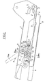
- La Figure 1 est une vue en élévation latérale d'un soubassement de siège de véhicule automobile pourvu d'un dispositif de réglage conforme à l'invention ;
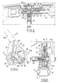
- La Figure 2 est une vue partielle à plus grande échelle prise en coupe suivant la ligne 2-2 de la Fig. 1 ou de la Fig. 3 ;
- La Figure 3 est une vue partielle, à la même échelle que la Fig.2, prise en coupe suivant la ligne 3-3 de la Fig. 1 ou de la Fig. 2 ;
- La Figure 4 est une vue schématique en élévation latérale du dispositif de réglage.
- Figure 1 is a side elevational view of a motor vehicle seat underbody provided with an adjustment device according to the invention;
- Figure 2 is a partial view on a larger scale taken in section along line 2-2 of FIG. 1 or of FIG. 3;
- Figure 3 is a partial view, on the same scale as Fig.2, taken in section along line 3-3 in Fig. 1 or of FIG. 2;
- Figure 4 is a schematic side elevational view of the adjustment device.
On voit à la Fig. 1 une armature de bas de siège 1 articulée par son bord arrière autour d'un axe horizontal 2. A chaque extrémité, l'axe 2 est solidaire d'une ferrure 3 fixée sur le profilé mobile 4 d'une coulisse 5 de réglage avant-arrière du siège dont le profilé fixe 6 est fixé au plancher du véhicule (non représenté).We see in Fig. 1 a seat bottom frame 1 articulated by its rear edge about a
Près de son extrémité avant, l'armature 1 porte d'un côté une plaque latérale 7 qui porte elle-même la partie mobile du dispositif 8 de réglage d'assiette, dont la partie fixe est constituée par une crémaillère verticale 9 à denture 10 en arc de cercle centrée sur l'axe 2 et tournée vers celui-ci. La crémaillère 9 est solidaire d'une ferrure 11 fixée au profilé mobile 4.Near its front end, the frame 1 carries on one side a
La partie mobile du dispositif 8 comprend un pignon double 12 tourillonnant sur un axe 13 tourillonnant lui-même sur la plaque 7, un levier d'actionnement 14 calé sur le même axe 13, et un secteur denté 15 en forme de haricot tourillonnant sur un second axe 16 solidaire de la plaque 7. Le levier 14 est constitué d'une manette 14a et d'une plaquette d'actionnement 14b toutes deux calées sur l'axe 13. Un ergot 17 en saillie sur le secteur 15 traverse une boutonnière 18 de la plaquette 14b et une boutonnière 19 de la plaque 7, tandis que l'axe 13 est guidé dans une boutonnière en arc de cercle 20 de la ferrure fixe 11 parallèle à la denture 10 de la crémaillère et voisine de celle-ci.The movable part of the
Le levier 14 est sollicité vers sa position de blocage, c'est-à-dire dans le sens antihoraire en considérant les Fig. 1 et 4, par un ressort de traction 21 agissant entre un appendice 22 de la plaquette 14b et l'armature 1. Le pignon 12 présente une petite denture 23 à six dents en prise par une ou deux dents avec la denture 10 de la crémaillère, et une grande denture 24 à seize dents en prise par quatre dents avec le secteur 15 lorsque le levier 14 est au repos (Fig. et 4).The
Plus précisément, dans la position de repos du levier 14, la boutonnière 18 de ce dernier est orientée à peu près verticalement et coupe l'extrémité inférieure de la boutonnière 19 de la plaque 7, qui est inclinée à peu près à 30° sur l'horizontale. L'ergot 17 se trouve alors en butée contre l'extrémité inférieure de la boutonnière 19 et proche de celle de la boutonnière 18.More precisely, in the rest position of the
Lorsqu'on tire sur la manette 14a pour la faire tourner dans le sens horaire (flèche f de la Fig. 4) à l'encontre du ressort 21, la boutonnière 18 tourne autour de l'axe 13 et vient dans la position 18A de la Fig. 4. Ceci oblige l'ergot 17 à se déplacer jusqu'à l'autre extrémité de la boutonnière 19, contre laquelle il vient buter (position 17A de la Fig. 4). L'ergot 17 entraîne dans son mouvement le secteur 15, qui tourne dans le sens antihoraire autour de l'axe 16 en libérant la denture 24 du pignon 12.When the
Il est alors possible de soulever ou d'abaisser l'avant du siège pour modifier son assiette. La denture 23 du pignon roule sur la denture 10 de la crémaillère, le guidage étant assuré par la boutonnière fixe 20. Quand la nouvelle position désirée est atteinte, on relâche la manette 14a, ce qui ramène sous l'effet du ressort 21 la boutonnière 18, l'ergot 17 et le secteur 15 dans leurs positions initiales, le secteur 15 revenant en prise avec la denture 24.It is then possible to raise or lower the front of the seat to modify its attitude. The
L'autre côté du soubassement (non représenté) comporte les mêmes organes, à l'exception de la manette 14a du levier 14. La synchronisation des mouvements est assurée par une entretoise 25 qui relie rigidement les deux axes 13.The other side of the base (not shown) comprises the same members, with the exception of the
On comprend que la finesse du réglage est définie par le pas angulaire de la denture 24, qui est très inférieur à celui des dentures 23 et 10. Le nombre de crans de réglage est donc très supérieur au nombre de dents de la crémaillère 9, lesquelles peuvent être relativement grossières. En d'autres termes, le poids est supporté par seulement une ou deux des dents 10 et 23, ce qui facilite la fabrication.It is understood that the fineness of the adjustment is defined by the angular pitch of the
De plus, l'effort est démultiplié de la crémaillère au secteur 15 dans le rapport des deux diamètres. Le secteur 15 est donc facile à déverrouiller. Les dents 24 ont à peu près les mêmes dimensions que les dents 23 ; Elles pourraient en toute rigueur être plus petites, mais ceci les rendrait plus délicates à réaliser sans apporter d'avantage supplémentaire, la précision du réglage de rehausse étant déjà suffisante, du moins pour l'application considérée.In addition, the effort is multiplied from the rack to
Claims (4)
Applications Claiming Priority (2)
| Application Number | Priority Date | Filing Date | Title |
|---|---|---|---|
| FR8111979 | 1981-06-17 | ||
| FR8111979A FR2508198A1 (en) | 1981-06-17 | 1981-06-17 | DEVICE FOR ADJUSTING THE HEIGHT OF AN ELEMENT AND ITS APPLICATION TO A VEHICLE SEAT BASE |
Publications (2)
| Publication Number | Publication Date |
|---|---|
| EP0067735A1 EP0067735A1 (en) | 1982-12-22 |
| EP0067735B1 true EP0067735B1 (en) | 1985-08-28 |
Family
ID=9259643
Family Applications (1)
| Application Number | Title | Priority Date | Filing Date |
|---|---|---|---|
| EP82400894A Expired EP0067735B1 (en) | 1981-06-17 | 1982-05-14 | Height adjusting mechanism for a vehicle seat |
Country Status (9)
| Country | Link |
|---|---|
| US (1) | US4469301A (en) |
| EP (1) | EP0067735B1 (en) |
| JP (1) | JPS57209433A (en) |
| BR (1) | BR8203524A (en) |
| CA (1) | CA1192483A (en) |
| DE (1) | DE3265795D1 (en) |
| ES (1) | ES266594Y (en) |
| FR (1) | FR2508198A1 (en) |
| MX (1) | MX158568A (en) |
Families Citing this family (4)
| Publication number | Priority date | Publication date | Assignee | Title |
|---|---|---|---|---|
| DE3628685C1 (en) * | 1986-08-23 | 1988-03-10 | Daimler Benz Ag | Tilt-adjustable seat cushion for a vehicle seat |
| GB2334883B (en) * | 1998-02-27 | 2001-11-14 | Lear Corp | Automotive seat adjustment mechanisms |
| US6131935A (en) * | 1998-09-01 | 2000-10-17 | Judkins; James H. | Cycle rider front torso support |
| CA2296032A1 (en) | 2000-01-13 | 2001-07-13 | Dutailier International Inc. | Locking assembly for a rocking chair |
Family Cites Families (10)
| Publication number | Priority date | Publication date | Assignee | Title |
|---|---|---|---|---|
| FR1376806A (en) * | 1963-10-12 | 1964-10-31 | Keiper Fritz | Hinge insert for adjustable backrests |
| US3695570A (en) * | 1969-10-22 | 1972-10-03 | Nissan Motor | Adjustable reclining seat |
| JPS499509B1 (en) * | 1970-12-21 | 1974-03-05 | ||
| JPS5016220B2 (en) * | 1971-10-18 | 1975-06-11 | ||
| JPS4928467A (en) * | 1972-07-14 | 1974-03-13 | ||
| US3912215A (en) * | 1973-02-10 | 1975-10-14 | Keiper Fritz | Seat construction |
| FR2254198A5 (en) * | 1973-12-05 | 1975-07-04 | Faure Bertrand | |
| IT1123276B (en) * | 1978-09-23 | 1986-04-30 | Keiper Automobiltechnik Gmbh | DEVICE FOR THE ADJUSTMENT OF THE INCLINATION OF SEATS, IN PARTICULAR VEHICLE SEATS |
| DE2933092A1 (en) * | 1979-08-16 | 1981-02-26 | Keiper Automobiltechnik Gmbh | FRAME FOR A LENGTH AND HEIGHT ADJUSTABLE VEHICLE SEAT |
| FR2469317A1 (en) * | 1979-11-14 | 1981-05-22 | Faure Bertrand | IMPROVEMENTS ON ADJUSTABLE VEHICLE SEATS AND THEIR ADJUSTMENT MECHANISMS |
-
1981
- 1981-06-17 FR FR8111979A patent/FR2508198A1/en active Granted
-
1982
- 1982-05-14 DE DE8282400894T patent/DE3265795D1/en not_active Expired
- 1982-05-14 EP EP82400894A patent/EP0067735B1/en not_active Expired
- 1982-06-03 CA CA000404360A patent/CA1192483A/en not_active Expired
- 1982-06-07 US US06/385,987 patent/US4469301A/en not_active Expired - Fee Related
- 1982-06-08 JP JP57098384A patent/JPS57209433A/en active Pending
- 1982-06-15 MX MX193153A patent/MX158568A/en unknown
- 1982-06-16 BR BR8203524A patent/BR8203524A/en unknown
- 1982-06-17 ES ES1982266594U patent/ES266594Y/en not_active Expired
Also Published As
| Publication number | Publication date |
|---|---|
| ES266594U (en) | 1983-03-01 |
| EP0067735A1 (en) | 1982-12-22 |
| FR2508198A1 (en) | 1982-12-24 |
| US4469301A (en) | 1984-09-04 |
| JPS57209433A (en) | 1982-12-22 |
| BR8203524A (en) | 1983-06-14 |
| MX158568A (en) | 1989-02-15 |
| DE3265795D1 (en) | 1985-10-03 |
| CA1192483A (en) | 1985-08-27 |
| ES266594Y (en) | 1983-09-01 |
| FR2508198B1 (en) | 1985-03-22 |
Similar Documents
| Publication | Publication Date | Title |
|---|---|---|
| CA2155424C (en) | Shelf with separations | |
| EP0888926B1 (en) | Vehicle seat with a neck protection device in case of rear impact | |
| EP0306374B1 (en) | Simple memory mechanism comprising a mechanical jack for the forward tilting movement of a vehicle seat | |
| EP0451035A1 (en) | Vehicle seats with integral seat belt | |
| FR2548107A1 (en) | SEAT ADJUSTMENT DEVICE, PARTICULARLY FOR VEHICLE SEATS | |
| EP1221348B1 (en) | Workpiece-supporting device for a bending machine | |
| EP0067735B1 (en) | Height adjusting mechanism for a vehicle seat | |
| FR2498132A1 (en) | DEVICE FOR ADJUSTING THE HEIGHT OF AN ELEMENT, PARTICULARLY A VEHICLE SEAT | |
| EP0026510B1 (en) | Device for transferring a motorially handicapped person from a wheelchair to a motor vehicle | |
| FR2463025A1 (en) | CHASSIS FOR A VEHICLE SEAT, MOVABLE LONGITUDINALLY AND IN HEIGHT | |
| FR2599313A1 (en) | VEHICLE CENTURY HAVING A SEAT SURFACE ADJUSTABLE AT HEIGHT AND INCLINATION. | |
| FR2503061A1 (en) | Vertical adjustment of vehicle seat front - comprises lever with toothed wheel engaging pinion in frame opening | |
| FR2719263A1 (en) | Backrest joint for a vehicle seat comprising a seat support and a backrest articulated to this support. | |
| EP0564372B1 (en) | Offset printing machine | |
| FR2775637A1 (en) | Adjuster for independent rear seats in vehicles | |
| CH164790A (en) | Articulated armchair. | |
| FR2527060A1 (en) | SEAT ASSEMBLY ADJUSTABLE TO TWO INDEPENDENT CONTROL MECHANISMS | |
| FR2718398A1 (en) | Adjustable seat for e.g. motor vehicles | |
| EP0566501A1 (en) | Articulation for an element of a reclining seat | |
| FR2619523A1 (en) | MACHINE FOR ASSEMBLING BODIES OF MOTOR VEHICLES OR THE LIKE | |
| EP0564360B1 (en) | Offset printing machine | |
| FR2578207A2 (en) | IMPROVEMENTS ON VEHICLE SEATS WITH TILT ADJUSTABLE BACKREST | |
| LU83198A1 (en) | IMPROVEMENTS ON APPARATUS FOR DISPENSING PRODUCTS IN ROLLS, PARTICULARLY PAPER HAND TOWELS | |
| EP0192006B1 (en) | Motor vehicle seat | |
| FR2484807A1 (en) | adjustment for vehicle seat - consists of two side support girders and two coaxial pinions |
Legal Events
| Date | Code | Title | Description |
|---|---|---|---|
| PUAI | Public reference made under article 153(3) epc to a published international application that has entered the european phase |
Free format text: ORIGINAL CODE: 0009012 |
|
| AK | Designated contracting states |
Designated state(s): DE GB IT SE |
|
| 17P | Request for examination filed |
Effective date: 19830613 |
|
| ITF | It: translation for a ep patent filed |
Owner name: MODIANO & ASSOCIATI S.R.L. |
|
| GRAA | (expected) grant |
Free format text: ORIGINAL CODE: 0009210 |
|
| AK | Designated contracting states |
Designated state(s): DE GB IT SE |
|
| REF | Corresponds to: |
Ref document number: 3265795 Country of ref document: DE Date of ref document: 19851003 |
|
| PLBE | No opposition filed within time limit |
Free format text: ORIGINAL CODE: 0009261 |
|
| STAA | Information on the status of an ep patent application or granted ep patent |
Free format text: STATUS: NO OPPOSITION FILED WITHIN TIME LIMIT |
|
| 26N | No opposition filed | ||
| PGFP | Annual fee paid to national office [announced via postgrant information from national office to epo] |
Ref country code: DE Payment date: 19900323 Year of fee payment: 9 |
|
| PGFP | Annual fee paid to national office [announced via postgrant information from national office to epo] |
Ref country code: GB Payment date: 19900508 Year of fee payment: 9 |
|
| PGFP | Annual fee paid to national office [announced via postgrant information from national office to epo] |
Ref country code: SE Payment date: 19900522 Year of fee payment: 9 |
|
| ITTA | It: last paid annual fee | ||
| PG25 | Lapsed in a contracting state [announced via postgrant information from national office to epo] |
Ref country code: GB Effective date: 19910514 |
|
| PG25 | Lapsed in a contracting state [announced via postgrant information from national office to epo] |
Ref country code: SE Effective date: 19910515 |
|
| GBPC | Gb: european patent ceased through non-payment of renewal fee | ||
| PG25 | Lapsed in a contracting state [announced via postgrant information from national office to epo] |
Ref country code: DE Effective date: 19920303 |
|
| EUG | Se: european patent has lapsed |
Ref document number: 82400894.0 Effective date: 19911209 |