EP0067664B1 - Compensated load cell - Google Patents
Compensated load cell Download PDFInfo
- Publication number
- EP0067664B1 EP0067664B1 EP82302992A EP82302992A EP0067664B1 EP 0067664 B1 EP0067664 B1 EP 0067664B1 EP 82302992 A EP82302992 A EP 82302992A EP 82302992 A EP82302992 A EP 82302992A EP 0067664 B1 EP0067664 B1 EP 0067664B1
- Authority
- EP
- European Patent Office
- Prior art keywords
- beams
- load cell
- strain gages
- resistors
- compensating
- Prior art date
- Legal status (The legal status is an assumption and is not a legal conclusion. Google has not performed a legal analysis and makes no representation as to the accuracy of the status listed.)
- Expired
Links
- 238000012360 testing method Methods 0.000 claims description 36
- 238000000034 method Methods 0.000 claims description 17
- 238000012937 correction Methods 0.000 description 5
- 238000005259 measurement Methods 0.000 description 3
- 230000003993 interaction Effects 0.000 description 2
- 238000010998 test method Methods 0.000 description 2
- 238000013459 approach Methods 0.000 description 1
- 238000005452 bending Methods 0.000 description 1
- 230000003247 decreasing effect Effects 0.000 description 1
- 238000010586 diagram Methods 0.000 description 1
- 238000006073 displacement reaction Methods 0.000 description 1
- 230000000694 effects Effects 0.000 description 1
- 238000013101 initial test Methods 0.000 description 1
- 238000003754 machining Methods 0.000 description 1
- 230000007935 neutral effect Effects 0.000 description 1
- 230000035945 sensitivity Effects 0.000 description 1
Images


Classifications
-
- G—PHYSICS
- G01—MEASURING; TESTING
- G01G—WEIGHING
- G01G3/00—Weighing apparatus characterised by the use of elastically-deformable members, e.g. spring balances
- G01G3/12—Weighing apparatus characterised by the use of elastically-deformable members, e.g. spring balances wherein the weighing element is in the form of a solid body stressed by pressure or tension during weighing
- G01G3/14—Weighing apparatus characterised by the use of elastically-deformable members, e.g. spring balances wherein the weighing element is in the form of a solid body stressed by pressure or tension during weighing measuring variations of electrical resistance
- G01G3/1402—Special supports with preselected places to mount the resistance strain gauges; Mounting of supports
- G01G3/1406—Special supports with preselected places to mount the resistance strain gauges; Mounting of supports combined with special measuring circuits
Definitions
- the present invention relates to improved load cells for precision measurements of weights and forces.
- French Patent 2,277,336 discloses a shear beam load cell in which strain gages are positioned on a vertical surface of a beam parallel to the direction of loads applied to the beam to sense shear strain.
- the strain gages are displaced from the neutral axis in a vertical direction to correct for interaction between bending and shear strain. Such an arrangement does not increase the sensitivity of the load cell to off-center loading in a lateral direction.
- U.S. Patent 3,576,128 discloses a load cell comprising two generally parallel beam members forming a parallelogram with a longitudinal axis parallel to the beams.
- the beam members are rigidly connected together at one end and attached to a support.
- the other ends are rigidly connected together and support a scale pan or platform.
- a pair of strain gages is attached to each of the beam members.
- a shunt resistor is connected across the strain gages at one end or the other of the load cell so that accurate force measurements independent of the load position along the longitudinal axis of the parallelogram may be obtained.
- Such resistors do not, however, make the output of the load .cell independent of the position of the load along axes transverse to the longitudinal axis. Instead, they frequently increase the variation of the output with position of the load along such axes.
- a force measuring load cell arrangement comprising two substantially parallel beams, means rigidly connecting respective one ends of the beams together, support means connected to said one ends of the beams, means rigidly connecting the other ends of the beams together, force receiving means supported by said other ends of the beams, strain gages connected in an electrical bridge circuit and mounted on surfaces of the beams normal to the direction of forces applied to the beams through the force receiving means, and a resistor connected to one of the strain gages on at least one of the beams, characterised in that at least one of the strain gages is mounted laterally toward one side of a first of the beams and at least one of the strain gages is mounted laterally toward the other side of the second of the beams, and in that the resistor has a value such that the output of the bridge circuit represents the magnitude of a force applied to the force receiving means independently of the lateral position of the force relative to the beams.
- the invention also provides a method of compensating a force measuring load cell arrangement including two substantially parallel beams rigidly connected at both ends, force receiving means supported by the beams and strain gages mounted on surfaces of the beams normal to the direction of forces applied to the beams through the force receiving means, characterised in that the method comprises the steps of placing at least one strain gage laterally toward one side of the first beam, placing at least one strain gage laterally toward the opposite side of the second beam, determining the values of one or more compensating resistors which, when connected in circuit with one or more respective strain gages will cause the response of the load cell to be independent of the location in at least the lateral direction of a force applied to the force receiving means, and connecting the one or more compensating resistors in circuit with the respective strain gages.
- the force responsive member 15 is in the form of a rectangle having an upper beam member 16 and a lower beam member 17.
- the left hand ends (as viewed in Figure 1) of these beams are connected by vertical member 18 and the right hand ends by vertical member 19.
- Members 18 and 19 are preferably integral with beam members 16 and 17 but if they are not so formed they are rigidly interconnected with members 16 and 17 to form the load responsive structure 15.
- Structure 15 is supported by a support 20 and in turn supports a load receiving platform 22 through member 21.
- member 21 rests on the top surface of beam 16. However, if desired it may be supported by vertical member 19.
- support 20 is shown on the lower surface of the beam 17. Support 20 may, however, be rigidly attached to vertical member 18.
- the upper beam 16 has two reduced sections 31 and 32. A strain gage 1 is attached to the upper surface of beam 16 adjacent to reduced section 31 and a strain gage 2 is attached to the upper surface of beam 16 over reduced section 32. While strain gages 1 and 2 are shown applied to the upper surface of beam 16 in accordance with the exemplary embodiment of the invention described herein, they may equally well be applied to the beam within the reduced sections 31 and 32, respectively, on the lower surface of beam 16.
- lower beam 17 is provided with reduced sections 33 and 34. Strain gages 3 and 4 are applied on the outside surface of beam 17 adjacent to these reduced sections. However, as with upper beam 16 these strain gages may be applied within the reduced sections 33 and 34, respectively, of beam 17. Further, the present invention does not require that beams 16 and 17 be provided with the reduced sections 31, 32 and 33, 34. The beams may instead be of substantially uniform dimension without the reduced sections.
- each strain gage 1, 2, 3 and 4 was positioned over the center line of the top surface of beam 16 or the bottom surface of beam 17.
- the reduced sections 31-34 were filed or honed in an effort to reduce these inaccuracies. This solution is both costly and time consuming since it involves "cut and try" procedures where only a small amount of material can be removed at any time before testing. If too much material is removed, the load capacity of the structure is reduced so that the entire structure must be discarded.
- the errors due to shifting of the load to different positions on the platform generally arise from slight variations of many factors.
- Some of the factors that may affect the accuracy of the weight measurements when the load is shifted (off center) on the platform include: (1) small variations in the position of the strain gages on the beams, (2) variations in the bonding of the strain gages to the beams, (3) strain gage geometry variations, (4) strain gage resistance variations, (5) strain gage factor variations, (6) variations in the load cell geometry, (7) variations in the thickness of the reduced sections of the beams, (8) variations in the location of the reduced sections, (9) variation in the geometry of the reduced sections of the beams (10) variations in composition of the load cell, (11) variation in strains in the load cell due to machining and other factors, and (12) variations in the-lead wires and in the connecting circuitry.
- the strain gages of either or both of the vertical pairs 1,4 and 2, 3 of strain gages are displaced off the center lines of beams 16 and 17 toward opposite sides of the vertical central plane 30 ( Figures 2 and 3) through the load cell structure.
- strain gage 2 of vertical pair 2, 3 is displaced or placed to the right of vertical plane 30 while strain gage 3 is displaced to the left of plane 30.
- strain gage 1 is displaced to the right ( Figure 2) while strain gage 4 is displaced to the left with respect to vertical plane 30. While the strain gages are shown in the drawing placed completely on opposite sides of the central vertical plane 30, that is not essential.
- strain gages of both vertical pairs are shown displaced in the manner described above, it is not essential that the strain gages of both pairs be so displaced.
- the respective strain gages of only one pair may be displaced while the strain gages of the other pair are centrally located with respect to central vertical plane 30.
- compensating resistors are employed either in parallel or in series or both in series and in parallel with the strain gage resistances.
- resistors since there is no known method of determining beforehand the value of such resistors or in accordance with the prior art the amount or position to which material should be removed from the load cell structure, it is necessary to test each of the load cell structures individually.
- the strain gage resistors 1, 2, 3, 4 are connected in a bridge circuit as shown in Figure 4 so that the physically adjacent pairs of gages 1,2; 2,3; 3,4; and 4,1 on the load cell structure are electrically adjacent in the bridge circuit.
- the compensating resistors 11, 12, 13 and 14 are not connected in parallel with the respective strain gage resistors.
- One set of terminals of the bridge is connected to power source 24 and the other terminals are connected to an indicating device 40 which indicates the output of the strain gage resistor bridge.
- the indicator device 40 may be calibrated in any desired units. For convenience, the units will be referred to herein as counts.
- test weight is put on the platform 22 in different ones of the positions shown in Figure 5 and the differences in count output from indicator 40 are recorded.
- the test weight may be first placed in a central location c and then moved to position b and the difference in the outputs on device 40 is noted.
- the test weight is then moved to the longitudinal position e in Figure 5 and again the change in output from indicator 40 due to moving the test weight from position c to position e is noted.
- the column headed "No R" in Table I below shows typical variations in the output indications for moving the test weight from position c to b and from position c to position e.
- test resistor networks are connected to the strain gages.
- the networks may include series resistors, parallel resistors or both series and parallel resistors.
- a trial compensating resistor 11 is connected in parallel with strain gage 1 and a trial compensating resistor 12 connected in parallel with strain gage 2.
- These trial compensating resistors are of the same value so they do not unbalance the bridge circuit and are of some nominal value.
- a suitable value for the trial compensating resistors for the initial tests is approximately 4,000 ohms.
- test weight is again put in the center of the platform at location c, moved to location b and then moved to location e.
- the changes in the outputs from indicator 40 are determined and are shown in the R,R 2 column of Table I below.
- resistor 11 is disconnected from strain gage 1 and resistor 13 is connected across strain gage 3.
- Resistor 13 is again of the same value as resistors 11 and 12 so that with resistors 12 and 13 now connected across strain gages 2 and 3 the bridge circuit is again not unbalanced.
- the test weight is again applied at location c and then moved to locations b and e and the changes in the outputs of the load cell, as indicated on indicator 40, recorded as shown in column R 2 R 3 of Table I.
- compensating resistor 12 is disconnected from strain gage 2 and similar resistor 14 is connected across strain gage 4. The above test procedure is repeated, moving the weight from central location c to transverse location b and then to longitudinal location e.
- the output of a single strain gage is often expressed as where G is the resistance of the strain gage. If a shunt resistor of S ohms is connected across the strain gage, the output is reduced to where A is an attenuation constant having a value between 0 and 1 and is approximately equal to Now, the output of a strain gage bridge may be expressed as where AE is the change in output and V is the applied voltage.
- AE is the change in output
- V the applied voltage
- equations are written representing the required corrections.
- the constants are determined by tests and then the desired amount of correction or compensation is determined.
- the values of X and Y are substantially independent of each other.
- the units of Y, X, y, and x are increments of weight or, more specifically as used in the examples, counts.
- the x and y directions do not necessarily correspond to transverse and longitudinal directions on platform 22.
- One way to determine the constants in equation (9) is to place a test weight on platform 22 in different positions with test compensating resistors connected to different pairs of strain gages and utilize the output indications from indicator 40.
- One procedure utilizes data from placing the test weight at positions b, e, g and i or at positions a, d, f and h, as shown in Fig. 5, with test compensating resistors connected to the various pairs of strain gages.
- Table II below shows one set of such data where the test compensating shunt resistor S is aqain 4000 ohms.
- one line 50 can be drawn through the points for R l R 2 and R 3 R 4 and another line 51 intersecting the first through the points for R 2 R 3 and R 4 R,.
- the origin of the x,y axis represents the point of zero load shift error and the point x',y' represents the load shift error without compensation
- complete compensation for load shift can be obtained by placing the appropriate compensating resistance values across the appropriate strain gages such that the point x',y' is made to coincide with the origin of the x,y axis.
- the proper values of compensating resistances to accomplish this may be determined mathematically using Figure 6 and Table II. First, the x,y axes are rotated to define the X,Y axes parallel to the respective intersection lines 50,51. The X and Y coordinates (X',Y') of the point x',y' can then be determined to obtain the appropriate values of compensating resistors required.
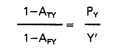
- the next step is to find A F y, the final attenuation term for changes in Y direction. From this the final trim resistors S• can be calculated.
- a ratio is formed where Py is the weight change between the weight represented by the point x',y' (or X',Y') and the weight represented by the coordinates of the test reading on line 51 in the direction of the needed correction.
- This weight change is represented in Figure 6 by the distance along line 51 from x',y' to x 2 ,y 2 .
- a FX P x is represented in Figure 6 by the distance along line 50 from x',y' to x 1 ,y 1 .
- a 6072 ohm resistor should be placed across gage 4, and a 3229 ohm resistor placed across gage 2.
- S FX and S FY in gives a resistor of 2108 ohms to be placed across gage 3.
- the error due to shifting of the weight on the scale platform may be reduced to a very small value.
- the test and final resistor networks connected to the strain gages may include series resistors rather than shunt resistors as in the exemplary embodiment described.
- the attenuation factor A for a series resistor connected to the strain gage must be used instead of that for a shunt resistor.
- the attenuation factor for the series resistor is where G is the resistance of the strain gage and T is the resistance of the series resistor. Except for using series resistors and the attenuation factor A for the series resistors, the procedure and calculations for compensating for load shifts are the same as those described above.
Landscapes
- Physics & Mathematics (AREA)
- General Physics & Mathematics (AREA)
- Measurement Of Force In General (AREA)
Description
- The present invention relates to improved load cells for precision measurements of weights and forces.
- French Patent 2,277,336 discloses a shear beam load cell in which strain gages are positioned on a vertical surface of a beam parallel to the direction of loads applied to the beam to sense shear strain. The strain gages are displaced from the neutral axis in a vertical direction to correct for interaction between bending and shear strain. Such an arrangement does not increase the sensitivity of the load cell to off-center loading in a lateral direction.
- U.S. Patent 3,576,128 discloses a load cell comprising two generally parallel beam members forming a parallelogram with a longitudinal axis parallel to the beams. The beam members are rigidly connected together at one end and attached to a support. The other ends are rigidly connected together and support a scale pan or platform. A pair of strain gages is attached to each of the beam members. In accordance with the U.S. Patent, a shunt resistor is connected across the strain gages at one end or the other of the load cell so that accurate force measurements independent of the load position along the longitudinal axis of the parallelogram may be obtained. Such resistors do not, however, make the output of the load .cell independent of the position of the load along axes transverse to the longitudinal axis. Instead, they frequently increase the variation of the output with position of the load along such axes.
- It is an object of this invention that disadvantages such as outlined above can be overcome and the output of the load cell can be made substantially independent of the position of the load along axes transverse to the longitudinal axis of the load cell.
- According to the present invention there is provided a force measuring load cell arrangement comprising two substantially parallel beams, means rigidly connecting respective one ends of the beams together, support means connected to said one ends of the beams, means rigidly connecting the other ends of the beams together, force receiving means supported by said other ends of the beams, strain gages connected in an electrical bridge circuit and mounted on surfaces of the beams normal to the direction of forces applied to the beams through the force receiving means, and a resistor connected to one of the strain gages on at least one of the beams, characterised in that at least one of the strain gages is mounted laterally toward one side of a first of the beams and at least one of the strain gages is mounted laterally toward the other side of the second of the beams, and in that the resistor has a value such that the output of the bridge circuit represents the magnitude of a force applied to the force receiving means independently of the lateral position of the force relative to the beams.
- The invention also provides a method of compensating a force measuring load cell arrangement including two substantially parallel beams rigidly connected at both ends, force receiving means supported by the beams and strain gages mounted on surfaces of the beams normal to the direction of forces applied to the beams through the force receiving means, characterised in that the method comprises the steps of placing at least one strain gage laterally toward one side of the first beam, placing at least one strain gage laterally toward the opposite side of the second beam, determining the values of one or more compensating resistors which, when connected in circuit with one or more respective strain gages will cause the response of the load cell to be independent of the location in at least the lateral direction of a force applied to the force receiving means, and connecting the one or more compensating resistors in circuit with the respective strain gages.
- An embodiment of the present invention will now be described by way of example only with reference to the accompanying drawings, in which:-
- Figure 1 is a side view of a scale including a load cell in accordance with this invention;
- Figure 2 is top view of the scale;
- Figure 3 is an end view of the scale;
- Figure 4 is a schematic diagram of a bridge circuit including the strain gages of the load cell of Figures 1 to 3 and illustrating how compensating resistors may be connected thereto;
- Figure 5 is a plan view of the scale of Figures 1 to 3 showing exemplary test positions for loads on the platform; and
- Figure 6 is a graph illustrating the effects of the values of the resistor networks connected to the various strain gages.
- Referring initially to Figures 1 to 3, the force
responsive member 15 is in the form of a rectangle having anupper beam member 16 and alower beam member 17. The left hand ends (as viewed in Figure 1) of these beams are connected byvertical member 18 and the right hand ends byvertical member 19.Members beam members members responsive structure 15. -
Structure 15 is supported by asupport 20 and in turn supports a load receivingplatform 22 throughmember 21. As shown,member 21 rests on the top surface ofbeam 16. However, if desired it may be supported byvertical member 19. Likewise,support 20 is shown on the lower surface of thebeam 17.Support 20 may, however, be rigidly attached tovertical member 18. Theupper beam 16 has two reducedsections strain gage 1 is attached to the upper surface ofbeam 16 adjacent to reducedsection 31 and astrain gage 2 is attached to the upper surface ofbeam 16 over reducedsection 32. Whilestrain gages beam 16 in accordance with the exemplary embodiment of the invention described herein, they may equally well be applied to the beam within the reducedsections beam 16. Likewise,lower beam 17 is provided with reducedsections 33 and 34.Strain gages beam 17 adjacent to these reduced sections. However, as withupper beam 16 these strain gages may be applied within the reducedsections 33 and 34, respectively, ofbeam 17. Further, the present invention does not require thatbeams sections - In the prior art, each strain gage 1, 2, 3 and 4 was positioned over the center line of the top surface of
beam 16 or the bottom surface ofbeam 17. However, with that arrangement it is highly desirable, if not necessary, to position the load at the center of platform 22 (location c in Figs. 2 and 5). If the load is placed at a different location the indicated weight is at least slightly inaccurate. In accordance with the prior art solution to this problem, the reduced sections 31-34 were filed or honed in an effort to reduce these inaccuracies. This solution is both costly and time consuming since it involves "cut and try" procedures where only a small amount of material can be removed at any time before testing. If too much material is removed, the load capacity of the structure is reduced so that the entire structure must be discarded. - The errors due to shifting of the load to different positions on the platform generally arise from slight variations of many factors. Some of the factors that may affect the accuracy of the weight measurements when the load is shifted (off center) on the platform include: (1) small variations in the position of the strain gages on the beams, (2) variations in the bonding of the strain gages to the beams, (3) strain gage geometry variations, (4) strain gage resistance variations, (5) strain gage factor variations, (6) variations in the load cell geometry, (7) variations in the thickness of the reduced sections of the beams, (8) variations in the location of the reduced sections, (9) variation in the geometry of the reduced sections of the beams (10) variations in composition of the load cell, (11) variation in strains in the load cell due to machining and other factors, and (12) variations in the-lead wires and in the connecting circuitry.
- In accordance with the present invention, the strain gages of either or both of the
vertical pairs beams strain gage 2 ofvertical pair vertical plane 30 whilestrain gage 3 is displaced to the left ofplane 30. Similarly,strain gage 1 is displaced to the right (Figure 2) whilestrain gage 4 is displaced to the left with respect tovertical plane 30. While the strain gages are shown in the drawing placed completely on opposite sides of the centralvertical plane 30, that is not essential. Instead, they may be displaced to a greater or lesser extent depending upon the various factors and dimensions of the load cell structure. Also, while the strain gages of both vertical pairs are shown displaced in the manner described above, it is not essential that the strain gages of both pairs be so displaced. The respective strain gages of only one pair may be displaced while the strain gages of the other pair are centrally located with respect to centralvertical plane 30. - In accordance with the present invention, instead of attempting to hone or cut the load cell structure to correct or eliminate errors due to placement of loads at different positions on
platform 22, compensating resistors are employed either in parallel or in series or both in series and in parallel with the strain gage resistances. However, since there is no known method of determining beforehand the value of such resistors or in accordance with the prior art the amount or position to which material should be removed from the load cell structure, it is necessary to test each of the load cell structures individually. - After the load cell has been constructed and assembled as described above, the
strain gage resistors gages resistors power source 24 and the other terminals are connected to an indicatingdevice 40 which indicates the output of the strain gage resistor bridge. Theindicator device 40 may be calibrated in any desired units. For convenience, the units will be referred to herein as counts. - After the bridge has been connected as described, a test weight is put on the
platform 22 in different ones of the positions shown in Figure 5 and the differences in count output fromindicator 40 are recorded. For example, the test weight may be first placed in a central location c and then moved to position b and the difference in the outputs ondevice 40 is noted. The test weight is then moved to the longitudinal position e in Figure 5 and again the change in output fromindicator 40 due to moving the test weight from position c to position e is noted. The column headed "No R" in Table I below shows typical variations in the output indications for moving the test weight from position c to b and from position c to position e. - Next, test resistor networks are connected to the strain gages. The networks may include series resistors, parallel resistors or both series and parallel resistors. In the exemplary embodiment described herein a trial compensating resistor 11 is connected in parallel with
strain gage 1 and atrial compensating resistor 12 connected in parallel withstrain gage 2. These trial compensating resistors are of the same value so they do not unbalance the bridge circuit and are of some nominal value. On a typical load cell where the gage resistors have a value of approximately 350 ohms, a suitable value for the trial compensating resistors for the initial tests is approximately 4,000 ohms. With a 4,000 ohm resistor connected in parallel with thestrain gage 1 and another in parallel withstrain gage 2 the test weight is again put in the center of the platform at location c, moved to location b and then moved to location e. As before, the changes in the outputs fromindicator 40 are determined and are shown in the R,R2 column of Table I below. - Next, resistor 11 is disconnected from
strain gage 1 andresistor 13 is connected acrossstrain gage 3.Resistor 13 is again of the same value asresistors 11 and 12 so that withresistors strain gages indicator 40, recorded as shown in column R2R3 of Table I. Next, compensatingresistor 12 is disconnected fromstrain gage 2 andsimilar resistor 14 is connected acrossstrain gage 4. The above test procedure is repeated, moving the weight from central location c to transverse location b and then to longitudinal location e. The differences in output fromindicator 40 are shown in column R3R4 of TableI. Compensating resistor 13 is then disconnected fromstrain gage 3 and compensating resistor 11 reconnected acrossstrain gage 1. The above test procedure is repeated and the differences recorded as in column R4R, of Table I.
- If it is desired to compensate only for transverse displacement (e.g. toward position b in Fig. 5) of the. load, columns No R and RlR2 of Table I show that a shunt resistor of 4,000 ohms across
strain gages - The output of a single strain gage is often expressed as


- Now connecting a test shunt resistor S across
strain gages 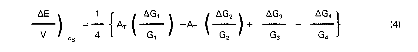


gages 


- Alternatively, the mid point between the test values in Table I for the test shunt across gages R1 and R2 (column R1R2) and the test shunt across gages R3 and R4 (column R3R4) may be used instead of the test value obtained with no shunt resistors connected to the bridge.

- The examples above involved compensation for transverse shift only, that is, from point c toward point b (or point g) in Fig. 5. If it is desired to compensate for longitudinal shift only, that is, from point c to point e (or point i) in Fig. 5, either of the above procedures may be followed using the second row of Table I and the values obtained with the test shunt resistors across either strain gages R2 and R3 or R1 and R4 or across both pairs.
- There is an interaction between the transverse and longitudinal shift compensations. If corrected independently, whenever one compensation is made it will change the amount of compensation required for shift of the other type. Thus, numerous corrections would have to be made in an iterative manner until the shift specifications are met. This approach is slow and costly.
- As a further aspect of the present invention, equations are written representing the required corrections. The constants are determined by tests and then the desired amount of correction or compensation is determined.
- For example, let

- y is the change in indicated weight observed when the applied load is shifted in one direction, identified as the y direction, and is a function of the values of the test compensating resistors;
- x is the change in indicated weight observed when the applied load is shifted in a direction substantially orthogonal to the y direction and identified as the x direction, and is a function of the values of the test. compensating resistors;
- Y is the change in load shift error resulting from the addition of compensating resistors to either opposite pair of adjacent strain gages, for
example gages - X is the change in load shift error resulting from the addition of compensating resistors to either opposite pair of adjacent gages not used in determining Y, for
example gages - A, B, C, D, E, and F are constants.
- As defined above, the values of X and Y are substantially independent of each other. The units of Y, X, y, and x are increments of weight or, more specifically as used in the examples, counts. Also, it should be noted that the x and y directions do not necessarily correspond to transverse and longitudinal directions on
platform 22. - One way to determine the constants in equation (9) is to place a test weight on
platform 22 in different positions with test compensating resistors connected to different pairs of strain gages and utilize the output indications fromindicator 40. One procedure utilizes data from placing the test weight at positions b, e, g and i or at positions a, d, f and h, as shown in Fig. 5, with test compensating resistors connected to the various pairs of strain gages. Table II below shows one set of such data where the test compensating shunt resistor S is aqain 4000 ohms.
- In Table 11, the differences between the readings at diagonally opposite corners (a,f and d,h in Fig. 5) of
platform 22 are determined and recorded as x and y values with test compensating resistors in place across the respective sets of strain gages. Readings need not be taken without test compensating resistors in place so that there is not a "No R" column in Table II. The "No R" points are determined from Table II as will become apparent below. - If the data from Table II are plotted on an x-y axis as shown in Fig. 6, one
line 50 can be drawn through the points for RlR2 and R3R4 and anotherline 51 intersecting the first through the points for R2R3 and R4R,. The lower the value of the test compensating shunt resistors S connected to the strain gages, the further the plotted points are from the intersection of the lines. The intersection is close to the uncompensated or "No R" point for load shift in either or both of the x and y directions. Changes in shift produced by placing shunt resistors across a pair of strain gages is represented by movement along the proper line. Increasing values of shunt resistors move the point along the line toward the intersection while decreasing values move it away from the intersection. - Since the origin of the x,y axis represents the point of zero load shift error and the point x',y' represents the load shift error without compensation, complete compensation for load shift can be obtained by placing the appropriate compensating resistance values across the appropriate strain gages such that the point x',y' is made to coincide with the origin of the x,y axis. In accordance with the present invention the proper values of compensating resistances to accomplish this may be determined mathematically using Figure 6 and Table II. First, the x,y axes are rotated to define the X,Y axes parallel to the
respective intersection lines - The relationship of the x,y axes to the X,Y axes is given by


- Solving for the coordinates X',Y' of the point x',y' in the X,Y coordinate system


lines 


- From this point the calculated values X' and Y' are utilized with the actual change caused by the test shunt resistors to determine the size of the needed final compensating resistors.
- The next step is to find AFy, the final attenuation term for changes in Y direction. From this the final trim resistors S• can be calculated. As in equation (8), a ratio is formed
line 51 in the direction of the needed correction. This weight change is represented in Figure 6 by the distance alongline 51 from x',y' to x2,y2. In this example, from Table II and Figure 6


line 50 from x',y' to x1,y1.


- Thus, a 6072 ohm resistor should be placed across
gage 4, and a 3229 ohm resistor placed acrossgage 2. Combining SFX and SFY in
gage 3. - Thus, the error due to shifting of the weight on the scale platform may be reduced to a very small value.
- As mentioned above, the test and final resistor networks connected to the strain gages may include series resistors rather than shunt resistors as in the exemplary embodiment described. In that case the attenuation factor A for a series resistor connected to the strain gage must be used instead of that for a shunt resistor. The attenuation factor for the series resistor is

Claims (15)
Applications Claiming Priority (2)
| Application Number | Priority Date | Filing Date | Title |
|---|---|---|---|
| US272928 | 1981-06-12 | ||
| US06/272,928 US4380175A (en) | 1981-06-12 | 1981-06-12 | Compensated load cell |
Publications (3)
| Publication Number | Publication Date |
|---|---|
| EP0067664A2 EP0067664A2 (en) | 1982-12-22 |
| EP0067664A3 EP0067664A3 (en) | 1984-06-06 |
| EP0067664B1 true EP0067664B1 (en) | 1987-01-28 |
Family
ID=23041863
Family Applications (1)
| Application Number | Title | Priority Date | Filing Date |
|---|---|---|---|
| EP82302992A Expired EP0067664B1 (en) | 1981-06-12 | 1982-06-10 | Compensated load cell |
Country Status (8)
| Country | Link |
|---|---|
| US (1) | US4380175A (en) |
| EP (1) | EP0067664B1 (en) |
| JP (1) | JPS582628A (en) |
| AU (1) | AU546438B2 (en) |
| BR (1) | BR8203456A (en) |
| CA (1) | CA1171691A (en) |
| DE (1) | DE3275318D1 (en) |
| NZ (1) | NZ200662A (en) |
Families Citing this family (49)
| Publication number | Priority date | Publication date | Assignee | Title |
|---|---|---|---|---|
| US4453609A (en) * | 1982-03-15 | 1984-06-12 | Reliance Electric Company | Compensated load cell |
| FR2536853A1 (en) * | 1982-11-30 | 1984-06-01 | Artigue Francis | WEIGHING APPARATUS WITH DEFORMATION GAUGES, ESPECIALLY A SCALE |
| JPS59116509A (en) * | 1982-12-24 | 1984-07-05 | Shimadzu Corp | Load cell scale |
| US4556115A (en) * | 1983-06-17 | 1985-12-03 | Hottinger Baldwin Measurement, Inc. | Method and means for equalizing the measuring sensitivity of a plurality of strain gage transducers |
| JPS6040930A (en) * | 1983-08-17 | 1985-03-04 | Toyo Baldwin:Kk | Single shaft load cell |
| CA1234589A (en) * | 1984-02-13 | 1988-03-29 | Reliance Electric Company | Load cell |
| US4657097A (en) * | 1984-02-13 | 1987-04-14 | Reliance Electric Company | Load cell |
| FR2580073B1 (en) * | 1985-04-09 | 1987-06-05 | Electro Resistance | |
| US4682664A (en) * | 1985-07-31 | 1987-07-28 | Canadian Corporate Management Co., Ltd. | Load sensing systems for conveyor weigh scales |
| JPS6333178Y2 (en) * | 1985-12-27 | 1988-09-05 | ||
| GB2184996A (en) * | 1986-01-04 | 1987-07-08 | Gen Electric Co Plc | Robot finger |
| US4768387A (en) * | 1987-05-13 | 1988-09-06 | Milltronics, Inc. | Flowmeter |
| US4799558A (en) * | 1987-06-12 | 1989-01-24 | Toledo Scale Corporation | Digital load shift compensation |
| FR2622695B1 (en) * | 1987-10-28 | 1990-09-07 | Electro Resistance | METHOD FOR ADJUSTING A RESISTIVE GAUGE OR TORQUE SENSOR |
| DE3739550C1 (en) * | 1987-11-21 | 1989-04-13 | Sartorius Gmbh | Electronic scale with electronic corner load correction |
| US4958526A (en) * | 1989-10-10 | 1990-09-25 | Flintab Ab | Force measuring device with zero adjustment |
| US4979580A (en) * | 1989-10-10 | 1990-12-25 | Flintab | Force measuring device with sensitivity equalization |
| US5004058A (en) * | 1990-03-27 | 1991-04-02 | Cardinal Scale Manufacturing Company | Weigh scale using multiple digital load cells |
| US5285019A (en) * | 1992-05-05 | 1994-02-08 | Endress + Hauser Inc. | Modular idler station belt scale apparatus |
| US5294756A (en) * | 1992-05-05 | 1994-03-15 | Endress+Hauser Inc. | Conveyor belt scale apparatus |
| JPH0630392U (en) * | 1992-09-24 | 1994-04-19 | 利春 高橋 | One-touch mounting type ventilation port |
| US5335554A (en) * | 1992-10-01 | 1994-08-09 | Endress + Hauser Inc. | Impact flowmeter |
| US5369226A (en) * | 1993-04-29 | 1994-11-29 | Mettler-Toledo, Inc. | Load shift compensation for weighing apparatus |
| US5510581A (en) * | 1994-05-18 | 1996-04-23 | Angel; Shlomo | Mass-produced flat multiple-beam load cell and scales incorporating it |
| US5886302A (en) * | 1995-02-08 | 1999-03-23 | Measurement Specialties, Inc. | Electrical weighing scale |
| DE19511353C1 (en) * | 1995-03-28 | 1996-07-11 | Sartorius Gmbh | Strain gauge weighing transducer with corner load correction |
| US5837946A (en) * | 1995-06-16 | 1998-11-17 | Weigh-Tronix, Inc. | Force sensitive scale and dual load sensor cell for use therewith |
| US5698794A (en) * | 1995-12-19 | 1997-12-16 | Thermo Sentron, Inc. | Impact flowmeter for solids |
| US5724267A (en) * | 1996-07-02 | 1998-03-03 | Richards; James L. | Weight measuring apparatus using a plurality of sensors |
| DE19632709C1 (en) * | 1996-08-14 | 1998-01-08 | Sartorius Gmbh | Electronic balance with parallel linkage guide and strain gauge corner load sensor |
| JP3727133B2 (en) * | 1997-03-14 | 2005-12-14 | 日本たばこ産業株式会社 | Load measuring method and load measuring apparatus |
| JPH10311753A (en) * | 1997-05-13 | 1998-11-24 | Yazaki Corp | Load measuring apparatus for vehicle |
| US6112162A (en) * | 1997-07-11 | 2000-08-29 | Richards; James L. | Weight measuring apparatus using a plurality of sensors |
| US6225576B1 (en) * | 1999-04-20 | 2001-05-01 | Cts Corporation | Shear beam load cell |
| US6330926B1 (en) | 1999-09-15 | 2001-12-18 | Hill-Rom Services, Inc. | Stretcher having a motorized wheel |
| US6677538B2 (en) * | 2000-02-25 | 2004-01-13 | Siemens Vdo Automotive Corporation | Signal processing in a vehicle weight classification system |
| US7014000B2 (en) | 2000-05-11 | 2006-03-21 | Hill-Rom Services, Inc. | Braking apparatus for a patient support |
| US6910392B2 (en) * | 2003-02-20 | 2005-06-28 | The Flintec Group, Ltd. | Bending beam load cell with torque sensitivity compensation |
| US7342185B2 (en) * | 2003-06-10 | 2008-03-11 | The Flintec Group, Ltd. | Compression column load cell with compensation for off center loading errors |
| US6888074B2 (en) * | 2003-06-10 | 2005-05-03 | The Flintec Group, Ltd. | Compression column load cell |
| DE102005038962A1 (en) * | 2005-08-16 | 2007-03-15 | Tecsis Gmbh | Connecting components for use in lorry, has extension sensor arranged parallel to beams, where attaching position, distance and length of posts are selected such that extension of sensor is independent of location of loading action |
| EP2060884A1 (en) * | 2006-09-05 | 2009-05-20 | Ishida Co., Ltd. | Load cell unit, weight checker, electronic weighting instrument, and weighting instrument |
| US20080154156A1 (en) * | 2006-12-21 | 2008-06-26 | Dellon A L | Method and apparatus for evaluation of neurosensory response |
| GB2475081A (en) * | 2009-11-05 | 2011-05-11 | Illinois Tool Works | A load cell having strain gauges to detect flexure in a beam using parallel resistors. |
| WO2015147586A1 (en) * | 2014-03-27 | 2015-10-01 | 이연석 | Weight measuring device capable of compensating for output characteristics |
| KR101503642B1 (en) | 2014-03-27 | 2015-03-17 | 이연석 | Load measuring device capable of output characteristic comoensation |
| ES2747986T3 (en) | 2015-02-27 | 2020-03-12 | Dow Global Technologies Llc | Procedures and systems for measuring the forces of a shrink film |
| CN108709673B (en) * | 2018-07-27 | 2023-09-26 | 北方民族大学 | Honing force testing device and honing force testing method |
| CN108801407A (en) * | 2018-08-02 | 2018-11-13 | 梅特勒-托利多(常州)测量技术有限公司 | Weighing device, weighing method, weighing sensor and storage medium |
Family Cites Families (8)
| Publication number | Priority date | Publication date | Assignee | Title |
|---|---|---|---|---|
| GB839121A (en) * | 1956-06-18 | 1960-06-29 | Coal Industry Patents Ltd | Improvements in and relating to load measuring apparatus |
| US3576128A (en) * | 1969-03-13 | 1971-04-27 | Blh Electronics | Half bridge moment desensitization of parallelogram-type beams |
| US3949603A (en) * | 1974-07-01 | 1976-04-13 | Hottinger Baldwin Measurements | Strain gage transducer |
| US3968683A (en) * | 1975-06-02 | 1976-07-13 | Alfred Neuman Ormond | Electrical equalization of load element sensitivity |
| CA1107310A (en) * | 1977-03-30 | 1981-08-18 | John M. Burke | Leverless scale sensor |
| US4128001A (en) * | 1977-09-16 | 1978-12-05 | Transducers, Inc. | Parallel beam load cell insensitive to point of application of load |
| JPS5572836A (en) * | 1978-11-27 | 1980-06-02 | Yamato Scale Co Ltd | Load cell |
| DE2933676C2 (en) * | 1979-08-20 | 1982-02-11 | Hottinger Baldwin Messtechnik Gmbh, 6100 Darmstadt | Procedure for adjusting transducers with strain gauges and strain gauges for carrying out the procedure. |
-
1981
- 1981-06-12 US US06/272,928 patent/US4380175A/en not_active Expired - Lifetime
-
1982
- 1982-05-18 NZ NZ200662A patent/NZ200662A/en unknown
- 1982-05-21 AU AU84017/82A patent/AU546438B2/en not_active Ceased
- 1982-06-01 JP JP57092231A patent/JPS582628A/en active Granted
- 1982-06-03 CA CA000404430A patent/CA1171691A/en not_active Expired
- 1982-06-10 EP EP82302992A patent/EP0067664B1/en not_active Expired
- 1982-06-10 DE DE8282302992T patent/DE3275318D1/en not_active Expired
- 1982-06-11 BR BR8203456A patent/BR8203456A/en not_active IP Right Cessation
Also Published As
| Publication number | Publication date |
|---|---|
| AU546438B2 (en) | 1985-08-29 |
| CA1171691A (en) | 1984-07-31 |
| EP0067664A2 (en) | 1982-12-22 |
| JPH0123053B2 (en) | 1989-04-28 |
| NZ200662A (en) | 1985-11-08 |
| AU8401782A (en) | 1982-12-16 |
| EP0067664A3 (en) | 1984-06-06 |
| DE3275318D1 (en) | 1987-03-05 |
| US4380175A (en) | 1983-04-19 |
| JPS582628A (en) | 1983-01-08 |
| BR8203456A (en) | 1983-06-07 |
Similar Documents
| Publication | Publication Date | Title |
|---|---|---|
| EP0067664B1 (en) | Compensated load cell | |
| EP0089209B1 (en) | Improved compensated load cell | |
| US4657097A (en) | Load cell | |
| US3927560A (en) | Moment desensitization of load cells | |
| US4128001A (en) | Parallel beam load cell insensitive to point of application of load | |
| US3949603A (en) | Strain gage transducer | |
| US4385527A (en) | Aircraft weighing systems | |
| EP1486762B1 (en) | Rod-shaped load cell | |
| US4556115A (en) | Method and means for equalizing the measuring sensitivity of a plurality of strain gage transducers | |
| US6910392B2 (en) | Bending beam load cell with torque sensitivity compensation | |
| EP0153121B2 (en) | Compensated load cell | |
| US4958526A (en) | Force measuring device with zero adjustment | |
| EP0114530B1 (en) | Weighing scale with a load cell | |
| JP2834282B2 (en) | Load cell | |
| EP0101247B1 (en) | Compensated multi-load cell scale | |
| US5369226A (en) | Load shift compensation for weighing apparatus | |
| US3194058A (en) | Weight and balance determination | |
| JPH0547389Y2 (en) | ||
| GB2128761A (en) | Force-measuring transducer | |
| CN115435879A (en) | Electronic scale and four-corner compensation method thereof | |
| JPH068742B2 (en) | Load cell type load cell |
Legal Events
| Date | Code | Title | Description |
|---|---|---|---|
| PUAI | Public reference made under article 153(3) epc to a published international application that has entered the european phase |
Free format text: ORIGINAL CODE: 0009012 |
|
| AK | Designated contracting states |
Designated state(s): BE CH DE FR GB LI SE |
|
| PUAL | Search report despatched |
Free format text: ORIGINAL CODE: 0009013 |
|
| AK | Designated contracting states |
Designated state(s): BE CH DE FR GB LI SE |
|
| 17P | Request for examination filed |
Effective date: 19840517 |
|
| GRAA | (expected) grant |
Free format text: ORIGINAL CODE: 0009210 |
|
| AK | Designated contracting states |
Kind code of ref document: B1 Designated state(s): BE CH DE FR GB LI SE |
|
| REF | Corresponds to: |
Ref document number: 3275318 Country of ref document: DE Date of ref document: 19870305 |
|
| ET | Fr: translation filed | ||
| PLBE | No opposition filed within time limit |
Free format text: ORIGINAL CODE: 0009261 |
|
| STAA | Information on the status of an ep patent application or granted ep patent |
Free format text: STATUS: NO OPPOSITION FILED WITHIN TIME LIMIT |
|
| BECH | Be: change of holder |
Free format text: 870128 *TOLEDO SCALE CORP. |
|
| 26N | No opposition filed | ||
| REG | Reference to a national code |
Ref country code: CH Ref legal event code: PUE Owner name: TOLEDO SCALE CORPORATION |
|
| REG | Reference to a national code |
Ref country code: CH Ref legal event code: PFA Free format text: TOLEDO SCALE CORPORATION |
|
| REG | Reference to a national code |
Ref country code: GB Ref legal event code: 732 |
|
| REG | Reference to a national code |
Ref country code: FR Ref legal event code: TP |
|
| REG | Reference to a national code |
Ref country code: CH Ref legal event code: PFA Free format text: METTLER-TOLEDO, INC. |
|
| REG | Reference to a national code |
Ref country code: FR Ref legal event code: CD |
|
| EAL | Se: european patent in force in sweden |
Ref document number: 82302992.1 |
|
| PGFP | Annual fee paid to national office [announced via postgrant information from national office to epo] |
Ref country code: GB Payment date: 19950530 Year of fee payment: 14 |
|
| PGFP | Annual fee paid to national office [announced via postgrant information from national office to epo] |
Ref country code: FR Payment date: 19950609 Year of fee payment: 14 |
|
| PGFP | Annual fee paid to national office [announced via postgrant information from national office to epo] |
Ref country code: SE Payment date: 19950615 Year of fee payment: 14 |
|
| PGFP | Annual fee paid to national office [announced via postgrant information from national office to epo] |
Ref country code: BE Payment date: 19950809 Year of fee payment: 14 |
|
| PG25 | Lapsed in a contracting state [announced via postgrant information from national office to epo] |
Ref country code: GB Effective date: 19960610 |
|
| PG25 | Lapsed in a contracting state [announced via postgrant information from national office to epo] |
Ref country code: SE Effective date: 19960611 |
|
| PG25 | Lapsed in a contracting state [announced via postgrant information from national office to epo] |
Ref country code: BE Effective date: 19960630 |
|
| BERE | Be: lapsed |
Owner name: METTLER-TOLEDO INC. Effective date: 19960630 |
|
| GBPC | Gb: european patent ceased through non-payment of renewal fee |
Effective date: 19960610 |
|
| PG25 | Lapsed in a contracting state [announced via postgrant information from national office to epo] |
Ref country code: FR Effective date: 19970228 |
|
| EUG | Se: european patent has lapsed |
Ref document number: 82302992.1 |
|
| REG | Reference to a national code |
Ref country code: FR Ref legal event code: ST |
|
| PGFP | Annual fee paid to national office [announced via postgrant information from national office to epo] |
Ref country code: DE Payment date: 19970613 Year of fee payment: 16 |
|
| PGFP | Annual fee paid to national office [announced via postgrant information from national office to epo] |
Ref country code: CH Payment date: 19970618 Year of fee payment: 16 |
|
| PG25 | Lapsed in a contracting state [announced via postgrant information from national office to epo] |
Ref country code: LI Free format text: LAPSE BECAUSE OF NON-PAYMENT OF DUE FEES Effective date: 19980630 Ref country code: CH Free format text: LAPSE BECAUSE OF NON-PAYMENT OF DUE FEES Effective date: 19980630 |
|
| REG | Reference to a national code |
Ref country code: CH Ref legal event code: PL |
|
| PG25 | Lapsed in a contracting state [announced via postgrant information from national office to epo] |
Ref country code: DE Free format text: LAPSE BECAUSE OF NON-PAYMENT OF DUE FEES Effective date: 19990401 |