EP0067427A2 - Gas suction method in coal mining, and suction pipe to perform this method - Google Patents
Gas suction method in coal mining, and suction pipe to perform this method Download PDFInfo
- Publication number
- EP0067427A2 EP0067427A2 EP19820105105 EP82105105A EP0067427A2 EP 0067427 A2 EP0067427 A2 EP 0067427A2 EP 19820105105 EP19820105105 EP 19820105105 EP 82105105 A EP82105105 A EP 82105105A EP 0067427 A2 EP0067427 A2 EP 0067427A2
- Authority
- EP
- European Patent Office
- Prior art keywords
- suction pipe
- cartridge
- suction
- plastic
- wall
- Prior art date
- Legal status (The legal status is an assumption and is not a legal conclusion. Google has not performed a legal analysis and makes no representation as to the accuracy of the status listed.)
- Withdrawn
Links
Images


Classifications
-
- E—FIXED CONSTRUCTIONS
- E21—EARTH DRILLING; MINING
- E21F—SAFETY DEVICES, TRANSPORT, FILLING-UP, RESCUE, VENTILATION, OR DRAINING IN OR OF MINES OR TUNNELS
- E21F7/00—Methods or devices for drawing- off gases with or without subsequent use of the gas for any purpose
Definitions
- the invention relates to a method for extracting gas in mining, in particular in coal mining, with the steps of drilling a hole in the mountains, inserting a suction pipe formed from rows of pipe sections, sealing the pipe against the bore wall at least at the end on the strut side and the Injecting liquid, foaming plastic into the annular space between the pipe and the bore wall.
- short-circuit area is to be understood as those parts of the borehole from which the longwall atmosphere emerges due to the proximity to the longwall or due to the porosity of the rock which happens to be present as soon as a negative pressure is applied there.
- the invention is seen in the fact that a reservoir for the plastic is attached to each pipe section and that the individual reservoirs are emptied into the annular space with the aid of a remote control.
- the method according to the invention also uses the principle of foaming the annular space between the bore wall and the suction pipe, the plastic is not filled into the annular space in one batch at a time, but instead plastic dumps are present along the suction pipe, which are activated as required for foaming can.
- plastic dumps are present along the suction pipe, which are activated as required for foaming can.
- full foaming can also be carried out at the start of the suction, compared with previously known methods significantly longer foaming lengths can be achieved. So far, the foaming was possible at a maximum length of approx. 8 m, which is primarily due to the fact that the injected liquid plastic begins to foam immediately and due to its increasing solidification and thus due to the increasing friction inside and at the limits of the Annulus the expandability decreases with increasing time since the injection. With the aid of the method according to the invention, however, foaming lengths of 14-20 m can easily be achieved.
- the respective reservoir is arranged in each case in the interior of the pipe section and that the plastic is conducted to the outside via lines.
- the placement of the plastic reservoirs in the interior of the suction tube has the particular advantage that each reservoir is protected from damage and so the emptying into the annular space only takes place when the corresponding remote control has been actuated.
- the free cross-sectional area reduced by the arrangement of the reservoir in the interior of the suction tube can be compensated for either by making the corresponding tube section in the area of the reservoir thicker-bellied or by the reservoir being torn off at a predetermined breaking point and being pulled out of the lower end of the suction tube ; in the latter procedure, however, immediate full foaming is required so that all reservoirs are removed from the suction tube when the suction begins.
- the invention proposes that one or more pipe sections are double-walled to form a reservoir filled with plastic, and that with the aid of a closure operated remotely through the pipe interior outer wall of the double tube can be opened.
- the closure can e.g. cause a displacement of the outer wall relative to the inner and thus an exposure of the plastic enclosed in the annular space of the double-walled tube when the closure is actuated. Deviating from this, deliberate damage in the form of cutting or perforating the outer wall of the double-walled tube is also possible.
- the invention proposes that one or more pipe sections are each provided with at least one line leading from a shut-off device of a plastic-containing cartridge to the outer wall, and that the shut-off device Cartridge consists of a remote-controlled valve.
- the remote control can easily consist of a rope that extends beyond the lower end of the suction pipe and engages an actuating lever of the valve. A tensile force applied to the rope opens the valve, whereby the plastic is emptied into the adjacent annular space between the suction pipe and the bore wall. The actual emptying takes place via a propellant gas located in the cartridge, the filling of which is dimensioned such that the plastic is completely expelled from the cartridge.
- the plastic is allowed to solidify and then another strong pull is exerted on the cable forming the remote control, which breaks the line and the rest of the line, the valve and the Cartridge formed unit can be pulled out of the lower end of the suction tube.
- the predetermined breaking point can be lacing can be generated at the specified point in the line. Deviating from this, the movement of the actuating lever in a first area can also open the valve and in a second area can cut through, for example, the line made of plastic as a result of a cut.
- the valve can also be designed as a compressed air valve, so that instead of the rope there is a hose connection to the valve, which can be activated by connecting a C0 2 cartridge or by connecting to the compressed air network, which is usually already present anyway of the valve can be applied.
- the pressure hose After the associated cartridge has been emptied into the corresponding annular space, the pressure hose also serves as a mechanical pulling device for removing the cartridge with the valve if the removal is necessary or desired.
- a cartridge in every second pipe section is normally sufficient if cartridges of approx. 5 cm diameter and a length of approx. 25 cm and customary dimensions for the borehole and the suction pipe are selected. With other pipe sections of approx. 1.5 m length, there is a satisfactory foaming, but in extreme cases, a normal, i.e. inactive pipe section can also be followed by two pipe sections, each with a cartridge, ie two active pipe sections.
- a particular advantage of this variant of the invention can be seen in the fact that the housing part receiving the piston is provided with a circumferential shoulder arranged below the lines. This shoulder ensures a stroke limitation of the piston, thereby ensuring that the lines leading the plastic outwards cannot be closed by the stroke.
- the annular space surrounding the piston extension underneath the shoulder compared to the piston surface of the piston to be pressurized, enables the foam emerging from the valve not to retract the piston and thus not to cause the valve to close automatically.
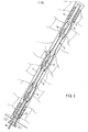
- a suction pipe 2 Arranged within a borehole 1 is a suction pipe 2, which is sealed externally with respect to the borehole 1 against the strut at its lower end by means of a sealing plug 3, for example made of polyurethane.
- the same sealing plug 3 is located just before the suction mouth of the suction pipe. It is composed alternately of active pipe sections 4 and inactive pipe sections 5, sleeves with lip seals being provided at the respective transition points.
- An active pipe section is to be understood as one with a plastic reservoir, in contrast to an inactive pipe section 5, which corresponds to previously known pipe sections.
- the active pipe sections 4 are enlarged in diameter in their central region, so that the plastic reservoir can be accommodated therein without hindering the free passage cross section, which e.g. is predetermined by the inactive pipe sections 5.
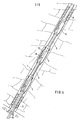
- FIG. 2 A widened section of an active pipe section 4 is shown in FIG. 2.
- a line 9 is attached within a wall 8 by means of collar bushings 10, which is connected to a valve 11 designed as a rotary ball valve.
- the valve 11 is followed by a cartridge 12 filled with a propellant gas and a liquid plastic suitable for foaming, for example polyurethane, which is arranged coaxially to the longitudinal axis of the active pipe section 4.
- the valve 11 is provided with an actuating lever 13 on which a cable 14 engages.
- the rope 14 extends through the entire suction pipe 2 and protrudes from its lower end so far that it is comfortable can be gripped.
- the cable 14 is pulled, whereby the valve 11 is opened.
- the propellant gas inside the cartridge 12 empties the plastic via line 9 into the corresponding annular space, with pre-foaming in line 9 and final foaming outside the line into the annular space.
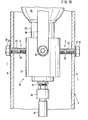
- FIG. 3 shows a view of the widened area of the active pipe section 4 according to FIG. 1.
- the line 9, which is designed as a T-piece, can be clearly seen within the outer wall 8.
- the valve arranged above and the cartridge 12 attached to it is schematically indicated as a circle.
- valve 11 and the cartridge 12 are not arranged coaxially to the longitudinal axis of the active pipe section 4, but rather eccentrically.
- the line 9 is not designed as a T-piece, but as a pure angle piece; there is also only a single opening into the annular space per valve 11 or per cartridge 12.
- FIGS. 1 and 4, 2 and 5 and 3 and 6 correspond, so that with regard to the explanation of the preceding description the corresponding figures can be referenced.
- FIG. 7 differs significantly from the two previously described. It can be seen that the active pipe sections 4 have no widening, that is to say correspond to the inactive pipe sections 5 with regard to their diameter. Nevertheless, they are provided with cartridges 12 (FIG. 8), which would seriously impede the free passage cross section in the position shown. For this reason, the cartridges and the valves must be removed from the interior of the suction pipe 2 after foaming.
- a compressed air valve 18 is provided in this exemplary embodiment, the locking member of which is displaced by the piston of a small pneumatic cylinder.
- a compressed air supply in the form of a hose 19 is required, which is guided through the interior of the suction pipe 2 instead of the cables 14.
- the hose 19 is connected to a pressure source, whereupon the propellant gas in the cartridge 12 pre-foams the plastic and drives it out of the outer wall 8 on both sides through the line 9.
- connection is sufficient, for example, to a C0 2 cartridge with the aid of an appropriate device, as is known, for example, from siphons and the like.
- an appropriate device as is known, for example, from siphons and the like.
- the compressed air supply that is usually present can also be tapped and used to actuate the compressed air valve 18.
- the compressed air valve 18 and the cartridge 12 After the foaming of the annular space around the outer wall 8, the compressed air valve 18 and the cartridge 12 be removed from the interior of the suction pipe 2 so that a usable free passage cross section is available.
- the line 9 is therefore weakened with respect to the diameter at the transition point to the mouth on the outer wall 8 at the points indicated by arrows, as a result of which a predetermined breaking point is present here.
- this predetermined breaking point tears, as a result of which the unit formed from the line residues, the compressed air valve 18 and the cartridge 12 is detached from the outer wall 8 and can be pulled out of the lower end of the exhaust pipe.
- S e stamped l is a predetermined breaking point with the embodiments according to FIGS. 2 and 5 also possible in connection with a cable 14.
- a predetermined breaking point can be present even if the active pipe section 4 has a thickening in the area of the plastic reservoir. It is in fact always possible that a rock falls approximately into the suction mouth of the suction pipe 2 from the inner diameter of the inactive pipe sections 5, which would not fall through the suction pipe 2 without removal, in particular the cartridges 12. In these cases, the general arrangement of a predetermined breaking point is recommended, so that the obstacle for any rocks of larger diameter that may have fallen into the suction pipe can be removed.
- the upper sealing plug 3 When the suction pipe 2 has reached its later desired position, the upper sealing plug 3 already has a considerable friction path from the beginning of the borehole 1 to its later position. The wear is correspondingly strong, so that there is a fear of impairing its sealing effect. For this reason, the pipe section, which carries the upper sealing plug 3, should always be followed by an active pipe section 4, so that the possibly reduced sealing effect by foaming the underneath lying area can be compensated. As a rule, the condition of the upper sealing plug 3 is still so good that the pressing plastic from the foaming process penetrates directly underneath between the sealing plug 3 and the borehole 1, but not into the suction mouth of the suction pipe 2. In this way it is ensured that unintentionally no foam gets into the suction mouth through the foaming in the upper area of the suction pipe 2.
- the third exemplary embodiment (FIGS. 7 and 8) is further developed by the fourth exemplary embodiment according to FIGS. 9 and 10.
- the cartridge 12 has at its lower end a neck 20 which has a tapered cross section compared to the other cartridge cross section.
- a valve housing 21 of the valve 18 which receives the triggering mechanism of the remote control is provided at the lower end with a shoulder 22 which can be inserted into the neck 20 and which has a circumferential groove 24 equipped with a sealing ring 22 for better hold and better sealing within the neck 20.
- the valve housing 21 is formed as a unit in the exemplary embodiment shown in the drawings.
- valve housing 21 with a screw closure that can be attached to the cartridge 12.
- the cartridge 12 connected to the valve housing 21 is fastened via the lines 9 in the wall 8 of an active pipe section 4.
- the lines 9 are designed as axially pierced screws 25, the screw heads 26 being attached to the outside of the wall 8.
- a sealing element 27 is provided between the screw heads 26 and the wall 8.
- the lines 9 are provided with predetermined breaking points 28.
- a piston 29 is attached orders, which is equipped on the top with a valve stem 17 opposite the piston extension 30 for actuation smaller cross-section.
- the housing part 31 is provided with a circumferential shoulder 32 below the lines 9.
- a connection piece 33 is arranged on the valve housing 21, to which the pressure medium line, which can be designed as a hose 19 and can be acted upon by compressed air, is connected by means of a quick-release fastener 34.
- the quick-release fastener 34 makes it possible to produce a fast connection between the pressure medium line and the valve housing 21 which can be subjected to tensile stress, which is important for the recovery of the cartridge 12 from the cased borehole.
- the piston extension 30 is wedge-shaped at its upper end. Furthermore, the screw heads 26 arranged on the outside of the piping are provided with check valves, for example with rubber membranes, in order to prevent the pressed-out plastic from reentering the inside of the piping. In order to avoid tearing off the valve housing 21 inserted into the neck 8 of the cartridge 12 when the cartridge 12 is recovered from the borehole, an additional holder 35 is provided between the valve housing 21 and the cartridge 12. On the circumference of the valve housing 21 there are two fastening elements 36, in the exemplary embodiment shown in FIG. 10, a screw extension, onto which a nut can be screwed, for fastening a holder 35, for example a metallic or plastic flat band, which is around the cartridge 12 is guided around.
- the valve housing 21 connected to the cartridge 12 is arranged fastened to the wall 8 ′ via only one line 9, similar to the second exemplary embodiment according to FIGS. 5 and 6.
- the screw head 26 is arranged in a recess in the wall 8 and on the inside the wall 8, a lock nut 37 is arranged to stabilize the line 9. In this way, premature destruction of the lines 9 is prevented in the event of transverse deformations of the piping or changes in cross-section of the wall 8 of the pipe sections 4.
Abstract
Description
Die Erfindung betrifft ein Verfahren zum Absaugen von Gas im Bergbau, insbesondere im Steinkohlenbergbau, mit den Schritten des Bohrens eines Loches in das Gebirge, des Einführens eines aus aneinandergereihten Rohrschüssen gebildeten Absaugrohres, des Abdichtens des Rohres gegenüber der Bohrungswandung mindestens an dem strebseitigen Ende und des Einspritzens von flüssigem, aufschäumendem Kunststoff in den Ringraum zwischen dem Rohr und der Bohrungswandung.The invention relates to a method for extracting gas in mining, in particular in coal mining, with the steps of drilling a hole in the mountains, inserting a suction pipe formed from rows of pipe sections, sealing the pipe against the bore wall at least at the end on the strut side and the Injecting liquid, foaming plastic into the annular space between the pipe and the bore wall.
Dieses Verfahren ist z.B. aus der DE-AS 22 55 267 bekannt. Dort wird vorgeschlagen, nach dem Einführen des Absaugrohres in das Bohrloch und nach dem Abdichten des Rohres gegenüber der Bohrungswandung an der Strebseite die maximale CH 4-Ergiebigkeit entlang des Bohrloches festzustellen, das Absaugrohr in dieser Lage zu fixieren und den Ringraum von der unteren Dichtung annähernd bis zur Saugmündung des Absaugrohres durch' Einspritzen von aufschäumendem Kunststoff auszufüllen und somit abzudichten.This method is known for example from DE-AS 22 55 267. There it is proposed that after inserting the suction tube into the borehole and after sealing the tube against the wall of the bore on the strut side determine maximum CH 4-coverage along the well bore, to fix the exhaust pipe in this position and approximately up to the suction mouth of the suction tube to fill the annular space from the lower seal by 'injection of plastic and thus intumescent seal.
Es hat sich in der Praxis jedoch gezeigt, daß das Bohrloch kurz nach seiner Fertigstellung infolge von Bewegungen innerhalb des Gebirges seine ursprüngliche Gestalt verliert und von Rissen, Scherungen und dergl. durchsetzt ist. Entsprechend ändert sich auch fortlaufend die CH4-Ergiebigkeit, so daß die anfänglich durch Messen geortete Stelle der maximalen CH4- Ergiebigkeit nach kurzer Zeit gewandert ist. Die vorher durchgeführten Messungen treffen dann nicht mehr zu, strenggenommen müßte dann die Lage der Saugmündung des Absaugrohres erneut verschoben werden. Dies ist jedoch aus praktischen Gründen nicht mehr möglich, wenn bereits der Ringraum zwischen dem Absaugrohr und der Bohrungswandung ausgeschäumt ist.In practice, however, it has been found that the borehole loses its original shape shortly after its completion as a result of movements within the mountains and is penetrated by cracks, shearings and the like. Correspondingly, the CH 4 yield also changes continuously, so that the location of the maximum CH 4 yield that was initially located by measuring has migrated after a short time. The measurements previously carried out then no longer apply; strictly speaking, the position of the suction mouth of the suction pipe would have to be shifted again. For practical reasons, however, this is no longer possible if the annular space between the suction pipe and the bore wall has already been foamed.
Die Bewegungen innerhalb des Gebirges sind so stark, daß es zu Verformungen des flexiblen, in der Regel aus Kunststoff hergestellten Absaugrohres kommt. An den mit Lippendichtungen versehenen Muffenverbindungen zwischen den einzelnen Rohrschüssen kann es dabei zu einer Aufhebung der Abdichtung kommen, so daß an dieser Stelle eine Absaugung eintritt, die möglicherweise in einem Bereich liegt, der als sogenannter Kurzschlußbereich anzusprechen ist. Unter dem Begriff "Kurzschlußbereich" sind diejenigen Partien des Bohrloches zu verstehen, aus denen aufgrund der Nähe zum Streb oder aufgrund der Porosität des zufällig hier vorhandenen Gebirges die Strebatmosphäre austritt, sobald dort ein Unterdruck angelegt wird. Das Zuschäumen derartiger Leckstellen innerhalb eines deformierten Absaugrohres war bei dem bisherigen Verfahren dann ausgeschlossen, wenn der darunterliegende Bereich ganz oder teilweise bereits ausgeschäumt war.The movements within the mountains are so strong that the flexible suction tube, usually made of plastic, is deformed. At the socket connections provided with lip seals between the individual pipe sections, the sealing can be broken, so that suction occurs at this point, which may be in an area which is to be referred to as a so-called short-circuit area. The term "short-circuit area" is to be understood as those parts of the borehole from which the longwall atmosphere emerges due to the proximity to the longwall or due to the porosity of the rock which happens to be present as soon as a negative pressure is applied there. The foaming of such leaks within a deformed suction pipe was ruled out in the previous method if the area underneath had already been partially or completely foamed.
Es ist demnach Aufgabe der Erfindung, ein Verfahren zum Absaugen von Gas im Steinkohlenbergbau anzugeben, das unempfindlicher gegenüber Verformungen des Bohrloches und damit gegenüber dem Absaugrohr und der damit gegebenenfalls verbundenen Leckstellen ist.It is therefore an object of the invention to provide a method for extracting gas in the coal industry, which is less sensitive to deformation of the borehole and thus to the suction pipe and any leakage associated therewith.
Die Erfindung wird darin gesehen, daß an einigen Rohrschüssen jeweils ein Reservoir für den Kunststoff angebracht wird und daß mit Hilfe einer Fernbedienung die einzelnen Reservoire in den Ringraum entleert werden.The invention is seen in the fact that a reservoir for the plastic is attached to each pipe section and that the individual reservoirs are emptied into the annular space with the aid of a remote control.
Das erfindungsgemäße Verfahren bedient sich zwar auch des Prinzips der Ausschäumung des Ringraumes zwischen der Bohrungswandung und dem Absaugrohr, der Kunststoff wird jedoch nicht in einer Charge auf einmal in den Ringraum gefüllt, sondern entlang des Absaugrohres sind Kunststoffdeponien vorhanden, die nach Bedarf zur Ausschäumung aktiviert werden können. Dadurch ergeben sich gegenüber bisherigen Verfahren erhebliche Vorteile. Genügt z.B. für eine erste Periode von mehreren Stunden die Abdichtung im unteren Bereich des Absaugrohres gegenüber der Bohrungswandung, wird durch Entleeren der unteren beiden Reservoire der Ringraum an dieser Stelle entsprechend gefüllt. Wenn dann später infolge einer inneren Bewegung des Gebirges eine Leckstelle beispielsweise im oberen Bereich des Absaugrohres eintritt, kann durch Entleeren weiterer Reservoire in der Umgebung der Leckstelle das Absaugen von Strebatmosphäre infolge eines Kurzschlusses vermieden und damit das Leck unschädlich gemacht werden. Bei dem bisherigen Verfahren wäre eine derartige Nachschäumung nicht möglich gewesen, da der bereits erhärtete Schaumpfropfen im unteren Bereich des Absaugrohres jede Zugänglichkeit für den darüberliegenden Bereich versperrt hätte.Although the method according to the invention also uses the principle of foaming the annular space between the bore wall and the suction pipe, the plastic is not filled into the annular space in one batch at a time, but instead plastic dumps are present along the suction pipe, which are activated as required for foaming can. This results in considerable advantages over previous methods. For example, For a first period of several hours, the seal in the lower area of the suction pipe against the wall of the bore is emptied accordingly by emptying the lower two reservoirs at this point. If a leak occurs later, for example in the upper area of the suction pipe, as a result of an internal movement of the mountains, the emptying of stratospheric atmosphere as a result of a short circuit can be avoided by emptying further reservoirs in the vicinity of the leak, and the leak can thus be rendered harmless. With the previous method, such post-foaming would not have been possible, since the already hardened foam plug in the lower region of the suction pipe would have blocked any access to the region above.
Neben dieser selektiven Ausschäumung entlang des Absaugrohres kann auch eine Vollschäumung schon zu Beginn der Absaugung vorgenommen werden, wobei gegenüber bisher bekannten Verfahren wesentlich längere Ausschäumlängen erzielt werden. Bisher war die Ausschäumung maximal auf einer Länge von ca. 8 m möglich, was in erster Linie daran liegt, daß der eingespritzte flüssige Kunststoff sofort zu schäumen beginnt und aufgrund seiner zunehmenden Erstarrung und damit durch die stärker werdende Reibung im Inneren sowie an den Begrenzungen des Ringraumes die Ausdehungsfähigkeit mit zunehmendem Zeitablauf seit dem Einspritzen abnimmt. Mit Hilfe des erfindungsgemäßen Verfahrens sind jedoch Ausschäumlängen von 14 - 20 m ohne weiteres erzielbar.In addition to this selective foaming along the suction pipe, full foaming can also be carried out at the start of the suction, compared with previously known methods significantly longer foaming lengths can be achieved. So far, the foaming was possible at a maximum length of approx. 8 m, which is primarily due to the fact that the injected liquid plastic begins to foam immediately and due to its increasing solidification and thus due to the increasing friction inside and at the limits of the Annulus the expandability decreases with increasing time since the injection. With the aid of the method according to the invention, however, foaming lengths of 14-20 m can easily be achieved.
In Weiterbildung des Verfahrens ist vorgesehen, daß das jeweilige Reservoir jeweils im Innern des Rohrschusses angeordnet ist und daß der Kunststoff über Leitungen auf die Außenseite geleitet wird.In a further development of the method, it is provided that the respective reservoir is arranged in each case in the interior of the pipe section and that the plastic is conducted to the outside via lines.
Die Unterbringung der Kunststoffreservoirse im Innern des Absaugrohres weist den besonderen Vorteil auf, daß jedes Reservoir vor Beschädigungen geschützt ist und so immer erst die Entleerung in den Ringraum erfolgt, wenn die entsprechende Fernbedienung betätigt worden ist. Die durch die Anordnung des Reservoirs im Innern des Absaugrohres verminderte freie Querschnittsfläche kann dadurch kompensiert werden, daß entweder der entsprechende Rohrschuß im Bereich des Reservoirs dickbauchiger ausgeführt ist oder daß das Reservoir nach der Entleerung an einer Sollbruchstelle abgerissen und aus dem unteren Ende des Absaugrohres herausgezogen wird; bei letzterer Verfahrensweise ist allerdings die sofortige Vollschäumung erforderlich, damit sämtliche Reservoire aus dem Absaugrohr entfernt sind, wenn die Absaugung beginnt.The placement of the plastic reservoirs in the interior of the suction tube has the particular advantage that each reservoir is protected from damage and so the emptying into the annular space only takes place when the corresponding remote control has been actuated. The free cross-sectional area reduced by the arrangement of the reservoir in the interior of the suction tube can be compensated for either by making the corresponding tube section in the area of the reservoir thicker-bellied or by the reservoir being torn off at a predetermined breaking point and being pulled out of the lower end of the suction tube ; in the latter procedure, however, immediate full foaming is required so that all reservoirs are removed from the suction tube when the suction begins.
Zur Durchführung des Verfahrens nach Anspruch 1 schlägt die Erfindung vor, daß ein oder mehrere Rohrschüsse doppelwandig zur Bildung eines mit Kunststoff gefüllten Reservoirs ausgebildet sind, und daß mit Hilfe eines durch das Rohrinnere fernbetätigten Verschlusses die äußere Wandung des Doppelrohres geöffnet werden kann.To carry out the method according to
Der Verschluß kann z.B. eine Verschiebung der äußeren Wandung gegenüber der inneren und damit eine Freilegung des in dem Ringraum des doppelwandigen Rohres eingeschlossenen Kunststoffes bei Betätigung des Verschlusses bewirken. Abweichend davon ist auch eine gewollte Beschädigung in Form eines Einschneidens oder Lochens der Außenwandung des doppelwandigen Rohres möglich.The closure can e.g. cause a displacement of the outer wall relative to the inner and thus an exposure of the plastic enclosed in the annular space of the double-walled tube when the closure is actuated. Deviating from this, deliberate damage in the form of cutting or perforating the outer wall of the double-walled tube is also possible.
Zur Durchführung des weitergebildeten Verfahrens mit einem Reservoir jeweils im Innern des entsprechenden Rohrschusses schlägt die Erfindung vor, daß ein oder mehrere Rohrschüsse jeweils mit mindestens einer Leitung versehen sind, die von einem Absperrorgan einer Kunststoff enthaltenden Patrone zu der Außenwandung führt, und daß das Absperrorgan der Patrone aus einem fernbedienten Ventil besteht.To carry out the further developed method with a reservoir each inside the corresponding pipe section, the invention proposes that one or more pipe sections are each provided with at least one line leading from a shut-off device of a plastic-containing cartridge to the outer wall, and that the shut-off device Cartridge consists of a remote-controlled valve.
Die Fernbedienung kann in einfacher Weise aus einem Seil bestehen, das bis über das untere Ende des Absaugrohres hinausgeführt ist und an einem Betätigungshebel des Ventils angreift. Eine an dem Seil aufgebrachte Zugkraft öffnet das Ventil, wodurch sich der Kunststoff in den benachbarten Ringraum zwischen dem Absaugrohr und der Bohrungswandung entleert. Die eigentliche Entleerung erfolgt dabei über ein in der Patrone befindliches Treibgas, dessen Füllung so bemessen ist, daß der Kunststoff vollständig aus der Patrone ausgetrieben wird.The remote control can easily consist of a rope that extends beyond the lower end of the suction pipe and engages an actuating lever of the valve. A tensile force applied to the rope opens the valve, whereby the plastic is emptied into the adjacent annular space between the suction pipe and the bore wall. The actual emptying takes place via a propellant gas located in the cartridge, the filling of which is dimensioned such that the plastic is completely expelled from the cartridge.
Soll die Patrone nach dem Ausschäumen aus dem Inneren des Absaugrohres entfernt werden, wird das Erstarren des Kunststoffes abgewartet und dann ein weiterer kräftiger Zug auf das die Fernbedienung bildende Seil ausgeübt, wodurch die Leitung zerbricht und die aus dem Rest der Leitung, dem Ventil und der Patrone gebildete Einheit aus dem unteren Ende des Absaugrohres herausgezogen werden kann. Die Sollbruchstelle kann durch eine Einschnürung an der vorgegebenen Stelle in der Leitung erzeugt werden. Abweichend davon kann auch die Bewegung des Betätigungshebels in einem ersten Bereich die öffnung des Ventils und in einem zweiten Bereich die Durchtrennung beispielsweise der aus Kunststoff hergestellten Leitung infolge eines Schnittes bewirken.If the cartridge is to be removed from the interior of the suction tube after foaming, the plastic is allowed to solidify and then another strong pull is exerted on the cable forming the remote control, which breaks the line and the rest of the line, the valve and the Cartridge formed unit can be pulled out of the lower end of the suction tube. The predetermined breaking point can be lacing can be generated at the specified point in the line. Deviating from this, the movement of the actuating lever in a first area can also open the valve and in a second area can cut through, for example, the line made of plastic as a result of a cut.
Neben einem Seil als Fernbedienung kann das Ventil auch als Druckluftventil ausgebildet sein, so daß statt des Seiles eine Schlauchverbindung zu dem Ventil vorhanden ist, die durch Anschluß einer C02-Patrone oder durch Anschluß an das in der Regel ohnehin vorhandene Druckluftnetz mit Druckluft zur Aktivierung des Ventils beaufschlagt werden kann. Nach der Entleerung der zugehörigen Patrone in den entsprechenden Ringraum dient der Druckschlauch noch als mechanische Zugeinrichtung zur Entfernung der Patrone mit dem Ventil, wenn die Beseitigung erforderlich oder erwünscht ist.In addition to a rope as a remote control, the valve can also be designed as a compressed air valve, so that instead of the rope there is a hose connection to the valve, which can be activated by connecting a C0 2 cartridge or by connecting to the compressed air network, which is usually already present anyway of the valve can be applied. After the associated cartridge has been emptied into the corresponding annular space, the pressure hose also serves as a mechanical pulling device for removing the cartridge with the valve if the removal is necessary or desired.
Statt einer Leitung können auch jeweils mehrere Leitungen einem Ventil und einer Patrone zugeordnet sein, damit die Ausschäumung des benachbarten Ringraumes möglichst gleichmäßig erfolgt. Die Häufigkeit eines mit einer Patrone versehenen Rohrschusses innerhalb des gesamten Absaugrohres richtet sich nach der in jeder Patrone enthaltenen Kunststoffmenge, der zu erwartenden Bewegung innerhalb des Gebirges sowie nach der Größe des auszuschäumenden Ringraumes. Normalerweise genügt eine Patrone in jedem zweiten Rohrschuß, wenn Patronen von ca. 5 cm Durchmesser und einer Länge von ca. 25 cm und übliche Abmessungen für das Bohrloch sowie das Absaugrohr gewählt werden. Bei sonstigen Rohrschüssen von ca. 1,5 m Länge ergibt sich dann eine befriedigende Ausschäumung, im Extremfall können jedoch einem normalen, also inaktiven Rohrschuß auch zwei Rohrschüsse mit jeweils einer Patrone, also zwei aktive Rohrschüsse folgen.Instead of one line, several lines can also be assigned to one valve and one cartridge so that the foaming of the adjacent annular space takes place as evenly as possible. The frequency of a pipe shot provided with a cartridge within the entire suction tube depends on the amount of plastic contained in each cartridge, the movement to be expected within the mountains and the size of the annular space to be foamed. A cartridge in every second pipe section is normally sufficient if cartridges of approx. 5 cm diameter and a length of approx. 25 cm and customary dimensions for the borehole and the suction pipe are selected. With other pipe sections of approx. 1.5 m length, there is a satisfactory foaming, but in extreme cases, a normal, i.e. inactive pipe section can also be followed by two pipe sections, each with a cartridge, ie two active pipe sections.
In Weiterbildung der Variante der Erfindung, bei der die Fernbedienung auf ein mit Druckmittel beaufschlagbares Ventil, insbesondere ein Druckluftventil wirkt, ist vorgesehen, daß in dem in einen Hals der Patrone einsteckbar ausgebildeten Ventilgehäuse ein mit einem gegen einen Ventilschaft gerichteten Kolbenfortsatz versehener Kolben angeordnet ist. Dadurch ergibt sich ein einfacher Aufbau der Einheit aus Patrone und Ventil, und hinsichtlich der Funktionsfähigkeit wird ein einwandfreies Austreten des Kunststoffs in den Ringraum zwischen dem Absaugrohr und der Bohrlochwandung gewährleistet.In a further development of the variant of the invention, in which the Remote control on a valve which can be acted upon by pressure medium, in particular a compressed air valve, is provided that a piston provided with a piston extension directed against a valve stem is arranged in the valve housing which can be inserted into a neck of the cartridge. This results in a simple construction of the unit from the cartridge and valve, and with regard to the functionality, a perfect escape of the plastic into the annular space between the suction pipe and the borehole wall is ensured.
Ein besonderer Vorteil dieser Variante der Erfindung ist darin zu sehen, daß der den Kolben aufnehmende Gehäuseteil mit einer unterhalb der Leitungen angeordneten umlaufenden Schulter versehen ist. Diese Schulter gewährleistet eine Hubbegrenzung des Kolbens, wodurch sichergestellt ist, daß die den Kunststoff nach außen führenden Leitungen durch den Hub nicht verschlossen werden können. Gleichzeitig ermöglicht der unterhalb der Schulter den Kolbenfortsatz umgebende Ringraum geringen Querschnitts gegenüber der mit einem Druckmittel zu beaufschlagenden Kolbenfläche des Kolbens, daß der aus dem Ventil austretende Schaum den Kolben nicht zurückfahren und somit ein selbsttätiges Schließen des Ventils nicht verursachen kann.A particular advantage of this variant of the invention can be seen in the fact that the housing part receiving the piston is provided with a circumferential shoulder arranged below the lines. This shoulder ensures a stroke limitation of the piston, thereby ensuring that the lines leading the plastic outwards cannot be closed by the stroke. At the same time, the annular space surrounding the piston extension underneath the shoulder, compared to the piston surface of the piston to be pressurized, enables the foam emerging from the valve not to retract the piston and thus not to cause the valve to close automatically.
Vorteilhafte Ausgestaltungen dieser Variante der Erfindung sind in den weiteren Unteransprüchen angegeben, und sie finden eine weitere Erläuterung im Zusammenhang mit der Beschreibung konkreter-Ausführungsbeispiele.Advantageous embodiments of this variant of the invention are specified in the further subclaims, and they find a further explanation in connection with the description of specific exemplary embodiments.
Nachfolgend werden Ausführungsbeispiele der Erfindung, die in der Zeichnung dargestellt sind, näher erläutert; darin bedeuten:
- Fig. 1 eine Querschnittsansicht durch ein Bohrloch mit einem Absaugrohr unter Verwendung der Erfindung,
- Fig. 2 eine Querschnittsansicht eines aktiven Rohrschusses gemäß der Erfindung zur Verwendung in dem Absaugrohr gemäß der Fig. 1,
- Fig. 3 eine Unteransicht des Rohrschusses gemäß der Fig. 2,
- Fig. 4 eine Ansicht gemäß der Fig. 1 zur Darstellung eines weiteren Ausführungsbeispiels der Erfindung,
- Fig. 5 eine Querschnittsansicht gemäß der Fig. 2 eines aktiven Rohrschusses zur Verwendung bei dem Ausführungsbeispiel gemäß der Fig. 4,
- Fig. 6 eine Unteransicht des Rohrschusses gemäß der Fig. 5,
- Fig. 7 eine Ansicht gemäß der Fig. 1 zur Darstellung eines dritten Ausführungsbeispiels der Erfindung,
- Fig. 8 eine Querschnittsansicht eines aktiven Rohrschusses zur Verwendung bei dem Ausführungsbeispiel gemäß der Fig. 7,
- Fig. 9 eine Querschnittsansicht eines vierten Ausführungsbeispiels als Weiterentwicklung des Ausführungsbeispiels nach Fig. 7 und 8,
- Fig. 10 eine Seitenansicht zu Fig. 9,
- Fig. 11 eine Seitenansicht einer Variante zu dem vierten Ausführungsbeispiel nach Fig. 9 und 10.
- 1 is a cross-sectional view through a borehole with a suction pipe using the invention;
- 2 shows a cross-sectional view of an active pipe section according to the invention for use in the suction pipe according to FIG. 1,
- 3 is a bottom view of the pipe section according to FIG. 2,
- 4 is a view according to FIG. 1 to show a further embodiment of the invention,
- 5 shows a cross-sectional view according to FIG. 2 of an active pipe section for use in the exemplary embodiment according to FIG. 4,
- 6 is a bottom view of the pipe section according to FIG. 5,
- 7 is a view according to FIG. 1 showing a third embodiment of the invention,
- 8 shows a cross-sectional view of an active pipe section for use in the exemplary embodiment according to FIG. 7,
- 9 shows a cross-sectional view of a fourth exemplary embodiment as a further development of the exemplary embodiment according to FIGS. 7 and 8,
- 10 is a side view of FIG. 9,
- 11 is a side view of a variant to the fourth exemplary embodiment according to FIGS. 9 and 10.
In Fig. 1 ist ein erstes Ausführungsbeispiel der Erfindung dargestellt. Innerhalb eines Bohrloches 1 ist ein Absaugrohr 2 angeordnet, das gegenüber dem Streb an seinem unteren Ende mit Hilfe eines Dichtungsstopfens 3 beispielsweise aus Polyurethan äußerlich gegenüber dem Bohrloch 1 abgedichtet ist. Ein gleicher Dichtungsstopfen 3 befindet sich kurz vor der Saugmündung des Absaugrohres. Es ist abwechselnd aus aktiven Rohrschüssen 4 und inaktiven Rohrschüssen 5 zusammengesetzt, wobei an den jeweiligen Übergangsstellen Muffen mit Lippendichtungen vorgesehen sind.1 shows a first exemplary embodiment of the invention. Arranged within a
Unter einem aktiven-Rohrschuß ist ein solcher mit einem Kunststoffreservoir zu verstehen, im Gegensatz zu einem inaktiven Rohrschuß 5, der bisher bekannten Rohrschüssen entspricht. Bei dem Ausführungsbeispiel gemäß der Fig. 1 sind die aktiven Rohrschüsse 4 in ihrem mittleren Bereich im Durchmesser vergrößert, so daß das Kunststoffreservoir darin Platz findet, ohne den freien Durchgangsquerschnitt zu behindern, der z.B. durch die inaktiven Rohrschüsse 5 vorgegeben ist.An active pipe section is to be understood as one with a plastic reservoir, in contrast to an
Ein verbreiterter Abschnitt eines aktiven Rohrschusses 4 ist in der Fig. 2 dargestellt. Innerhalb einer Wandung 8 ist eine Leitung 9 mit Hilfe von Bundbüchsen 10 angebracht, die mit einem als Drehkugelventil ausgebildeten Ventil 11 verbunden ist. An das Ventil 11 schließt sich eine mit einem Treibgas und flüssigem, zum Verschäumen geeigneten Kunststoff, z.B. Polyurethan gefüllte Patrone 12 an, die koaxial zur Längsachse des aktiven Rohrschusses 4 angeordnet ist. Das Ventil 11 ist mit einem Betätigungshebel 13 versehen, an dem ein Seil 14 angreift. Das Seil 14 erstreckt sich durch das gesamte Absaugrohr 2 und ragt aus dessen unterem Ende so weit hervor, daß es bequem ergriffen werden kann.A widened section of an
Sobald die Ausschäumung des Ringraumes in der Nachbarschaft eines bestimmten aktiven Rohrschusses 4 erwünscht ist, wird an dem Seil 14 gezogen, wodurch das Ventil 11 geöffnet wird. Das Treibgas innerhalb der Patrone 12 entleert den Kunststoff über die Leitung 9 in den entsprechenden Ringraum, wobei eine Vorschäumung in der Leitung 9 und ein endgültiges Ausschäumen außerhalb der Leitung in den Ringraum erfolgt.As soon as the foaming of the annular space in the vicinity of a certain
In der Fig. 3 ist eine Ansicht des verbreiterten Bereiches des aktiven Rohrschusses 4 gemäß der Fig. 1 gezeigt. Es ist deutlich die als T-Stück ausgebildete Leitung 9 innerhalb der Außenwandung 8 zu erkennen. Das darüber angeordnete Ventil sowie die daran befestigte Patrone 12 ist schematisch als Kreis angedeutet.FIG. 3 shows a view of the widened area of the
Soll z.B. eine Ausschäumung des Ringraumes zwischen den beiden Dichtungsstopfen 3 in der Anordnung nach Fig. 1 erfolgen, werden alle drei Seile 14 gleichzeitig oder in kurzen Abständen nacheinander gezogen, wodurch sich der Kunststoff aus den jeweiligen Patronen 12 in den entsprechenden Ringraum ergießt. Eine selektive Ausschäumung kann durch die gezielte Betätigung der Seile 14 erfolgen, die zur Kenntlichmachung ihrer Zugehörigkeit zu den einzelnen Ventilen 11 entweder farblich unterscheidbar oder mit einer Nummer versehen sind.Should e.g. If the annular space is foamed between the two sealing
Bei dem Ausführungsbeispiel gemäß der Fig. 4 ist das Ventil 11 sowie die Patrone 12 nicht koaxial zur Längsachse des aktiven Rohrschusses 4, sondern exzentrisch angeordnet. Auch ist die Leitung 9 nicht als T-Stück, sondern als reines Winkelstück ausgebildet; es ist auch pro Ventil 11 bzw. pro Patrone 12 nur eine einzige Mündung in den Ringraum vorhanden. Im übrigen entsprechen sich die Fig. 1 und 4, 2 und 5 sowie 3 und 6, so daß bezüglich der Erläuterung auf die vorangehende Beschreibung der entsprechenden Figuren verwiesen werden kann.In the exemplary embodiment according to FIG. 4, the
Das in Fig. 7 dargestellte Ausführungsbeispiel der Erfindung unterscheidet sich hingegen deutlich von den beiden bisher beschriebenen. Es ist zu erkennen, daß die aktiven Rohrschüsse 4 keinerlei Verbreiterung aufweisen, also bezüglich ihres Durchmessers den inaktiven Rohrschüssen 5 entsprechen. Dennoch sind sie mit Patronen 12 versehen (Fig. 8), die in der dargestellten Position den freien Durchgangsquerschnitt ernsthaft behindern würden. Aus diesem Grunde müssen die Patronen samt den Ventilen nach dem Ausschäumen aus dem Inneren des Absaugrohres 2 entfernt werden.The embodiment of the invention shown in FIG. 7, however, differs significantly from the two previously described. It can be seen that the
Doch zunächst sei noch eine andere Variante beschrieben. Statt eines Drehkugelventils ist bei diesem Ausführungsbeispiel ein Druckluftventil 18 vorhanden, dessen Sperrglied von dem Kolben eines kleinen Pneumatikzylinders verschoben wird. Zu dessen Betätigung wiederum ist eine Druckluftzuführung in Form eines Schlauches 19 erforderlich, der statt der Seile 14 durch das Innere des Absaugrohres 2 hindurchgeführt wird. Zur Aktivierung wird der Schlauch 19 an eine Druckquelle angeschlossen, worauf das in der Patrone 12 befindliche Treibgas den Kunststoff vorverschäumt und durch die Leitung 9 zu beiden Seiten aus der Außenwandung 8 heraustreibt.But first another variant is described. Instead of a rotary ball valve, a
Da zur Betätigung des Ventilkolbens nur ein sehr geringer Druck erforderlich ist, genügt der Anschluß beispielsweise an eine C02-Patrone unter Zuhilfenahme einer entsprechenden Vorrichtung, wie sie z.B. von Siphons und dergl. bekannt ist. Selbstverständlich kann auch die in der Regel vorhandene Druckluftversorgung angezapft und zur Betätigung des Druckluftventiles 18 herangezogen werden.Since only a very low pressure is required to actuate the valve piston, the connection is sufficient, for example, to a C0 2 cartridge with the aid of an appropriate device, as is known, for example, from siphons and the like. Of course, the compressed air supply that is usually present can also be tapped and used to actuate the
Nach dem Ausschäumen des Ringraumes um die Außenwandung 8 herum muß das Druckluftventil 18 sowie die Patrone 12 aus dem Inneren des Absaugrohres 2 entfernt werden, damit ein brauchbarer freier Durchgangsquerschnitt vorhanden ist. Die Leitung 9 ist deshalb an der Übergangsstelle zur Mündung an der Außenwandung 8 an den mit Hilfe von Pfeilen bezeichneten Stellen bezüglich des Durchmessers geschwächt, wodurch hier eine Sollbruchstelle vorhanden ist. Durch Aufbringen einer energischen Zugkraft an dem Schlauch 19 zerreißt diese Sollbruchstelle, wodurch die aus den Leitungsresten, dem Druckluftventil 18 sowie der Patrone 12 gebildete Einheit von der Außenwandung 8 gelöst ist und aus dem unteren Ende des Abgasrohres herausgezogen werden kann.After the foaming of the annular space around the
Selbstverständlichlist eine Sollbruchstelle auch mit den Ausführungsbeispielen gemäß den Fig. 2 und 5 auch in Verbindung mit einem Seil 14 möglich. Eine Sollbruchstelle kann selbst dann vorhanden sein, wenn der aktive Rohrschuß 4 im Bereich des Kunststoffreservoirs eine Verdickung aufweist. Es ist nämlich stets möglich, daß in die Saugmündung des Absaugrohres 2 ein Gesteinsbrocken annähernd vom inneren Durchmesser der inaktiven Rohrschüsse 5 hineinfällt, der ohne Beseitigung,insbesondere der Patronen 12, nicht durch das Absaugrohr 2 hindurchfallen würde. Für diese Fälle empfiehlt sich die generelle Anordnung einer Sollbruchstelle, damit dann das Hindernis für einen eventuell in das Absaugrohr hineingefallenen Gesteinsbrocken größeren Durchmessers beseitigt werden kann. S elbstverständlich l is a predetermined breaking point with the embodiments according to FIGS. 2 and 5 also possible in connection with a
Wenn das Absaugrohr 2 seine spätere Sollage erreicht hat, hat der obere Dichtungsstopfen 3 bereits einen erheblichen Reibungsweg vom Beginn des Bohrloches 1 an bis zu seiner späteren Stellung hinter sich. Entsprechend stark ist auch die Abnutzung, so daß eine Beeinträchtigung seiner Dichtwirkung zu befürchten ist. Aus diesem Grunde sollte dem Rohrschuß, der den oberen Dichtungsstopfen 3 trägt, stets ein aktiver Rohrschuß 4 folgen, damit die eventuell verminderte Dichtwirkung durch Ausschäumen des darunterliegenden Bereiches ausgeglichen werden kann. In der Regel ist der Zustand des oberen Dichtungsstopfens 3 noch so gut, daß zwar der nachdrängende Kunststoff von dem Ausschäumungsvorgang unmittelbar darunter zwischen den Dichtungsstopfen 3 und das Bohrloch 1 dringt, nicht jedoch in die Saugmündung des Absaugrohres 2. Auf diese Weise ist sichergestellt, daß unbeabsichtigt kein Schaum durch das Ausschäumen im oberen Bereich des Absaugrohres 2 in dessen Saugmündung gelangt.When the
Das dritte Ausführungsbeispiel (Fig. 7 und 8)wird durch das vierte Ausführungsbeispiel gemäß Fig. 9 und 10 weiterentwickelt. Hierbei weist die Patrone 12, wie insbesondere aus der Schnittzeichnung in Fig. 9 zu entnehmen ist, an ihrem unteren Ende gegenüber dem sonstigen Patronenquerschnitt einen einen verjüngten Querschnitt aufweisenden Hals 20 auf. Ein den Auslösemechanismus der Fernbedienung aufnehmendes Ventilgehäuse 21 des Ventils 18 ist am unteren Ende mit einem in den Hals 20 einsetzbaren Absatz 22 versehen, der zum besseren Halt und zur besseren Abdichtung innerhalb des Halses 20 eine mit einem Dichtungsring 22 ausgerüstete umlaufende Nut 24 aufweist. Das Ventilgehäuse 21 ist in dem in den Zeichnungen dargestellten Ausführungsbeispiel als eine Einheit ausgebildet.The third exemplary embodiment (FIGS. 7 and 8) is further developed by the fourth exemplary embodiment according to FIGS. 9 and 10. Here, as can be seen in particular from the sectional drawing in FIG. 9, the
Es ist jedoch auch vorstellbar, das Ventilgehäuse 21 mit einem auf die Patrone 12 aufbringbaren Schraubverschluß zu verbinden. Die mit dem Ventilgehäuse 21 verbundene Patrone 12 ist über die Leitungen 9 in der Wandung 8 eines aktiven Rohrschusses 4 befestigt. Die Leitungen 9 sind in den dargestellten Ausführungsbeispielen (auch in Fig. 11) als axial durchbohrte Schrauben 25 ausgebildet, wobei die Schraubenköpfe 26 außen an der Wandung 8 angebracht sind. Zusätzlich ist zwischen den Schraubenköpfen 26 und der Wandung 8 ein Dichtungselement 27 vorgesehen. Die Leitungen 9 sind mit Sollbruchstellen 28 versehen. Innerhalb des Ventilgehäuses 21 ist ein Kolben 29 angeordnet, der auf der Oberseite mit einem einem Ventilschaft 17 zwecks Betätigung gegenüberliegenden Kolbenfortsatz 30 geringeren Querschnitts ausgerüstet ist. Zur Begrenzung des Kolbenhubs ist der Gehäuseteil 31 unterhalb der Leitungen 9 mit einer umlaufenden Schulter 32 versehen.However, it is also conceivable to connect the
An dem Ventilgehäuse 21 ist ein Anschlußstutzen 33 angeordnet, mit dem mittels eines Schnellverschlusses 34 die beispielsweise als Schlauch 19 ausgebildete, über Druckluft beaufschlagbare Druckmittelleitung verbunden ist. Der Schnellverschluß 34 ermöglicht die Herstellung einer schnellen und auf Zug belastbaren Verbindung der Druckmittelleitung'mit dem Ventilgehäuse 21, was für die Wiedergewinnung der Patrone 12 aus dem verrohrten Bohrloch von Bedeutung ist. Um die Druckmittelleitung ständig wiederverwenden zu können, ist es vorteilhaft, diese aus einem längungsfreien Kunststoff mit oder ohne eine Armierung herzustellen.A
Um den Ausfluß des Kunststoffs aus der Patrone 12 zu gewährleisten, ist der Kolbenfortsatz 30 an seinem oberen Ende keilförmig ausgebildet. Desweiteren sind die auf der Außenseite der Verrohrung angeordneten-Schraubenköpfe 26, um ein Wiedereindringen des herausgepreßten Kunststoffs in den Innenbereich der Verrohrung zu verhindern, mit Rückschlagventilen, beispielsweise mit Gummimembranen versehen. Um beim Wiedergewinnen der Patrone 12 aus dem Bohrloch ein Abreißen des in den Hals 8 der Patrone 12 eingesteckten Ventilgehäuses 21 zu vermeiden, ist eine zusätzliche Halterung 35 zwischen Ventilgehäuse 21 und Patrone 12 vorgesehen. Am Umfang des Ventilgehäuses 21 sind gegenüberliegend zwei Befestigungselemente 36, in dem in Fig. 10 dargestellten Ausführungsbeispiel ein Schraubenfortsatz, auf welchen eine Mutter aufschraubbar ist, vorgesehen, zur Befestigung einer Halterung 35, beispielsweise eines metallischen oder aus Kunststoff hergestellten Flachbandes, welches um die Patrone 12 herumgeführt ist.In order to ensure the outflow of the plastic from the
Beim Einbringen der Verrohrung kann es passieren, daß die die Patrone 12 aufnehmende Wandung 8 innerhalb des Bohrlochs deformiert wird und sich im Querschnitt verringert. Dadurch kann es geschehen, daß die die Patrone 12 bzw. das Ventilgehäuse 21 tragenden Leitungen 9 im Bereich der Sollbruchstellen 28 vorzeitig abscheren. Die nachfolgende Verschäumung kann auf diese Weise im ungünstigsten Fall zu einem Bohrlochverschluß werden. Bei dem in Fig. 11 gezeigten Ausführungsbeispiel der Erfindung wird diese Gefahr vermieden. Das mit der Patrone 12 verbundene Ventilgehäuse 21 ist über nur eine Leitung 9 an der Wandung 8'befestigt angeordnet, ähnlich dem zweiten Ausführungsbeispiel gemäß Fig. 5 und 6. Der Schraubenkopf 26 ist in einer Ausnehmung in der Wandung 8 angeordnet, und auf der Innenseite der Wandung 8 ist zur Stabilisierung der Leitung 9 eine Kontermutter 37 angeordnet. Auf.diese Weise wird bei Querverformungen der Verrohrung bzw. bei Querschnittsveränderungen der Wandung 8 der Rohrschüsse 4 ein vorzeitiges Zerstören der Leitungen 9 verhindert.When installing the piping, it can happen that the
Claims (29)
Verfahren nach Anspruch 2, dadurch gekennzeichnet, daß jedes Reservoir über eine Sollbruchstelle mit dem jeweiligen Rohrschuß verbunden wird, und daß nach der Entleerung des Reservoirs und nach der Erstarrung des Kunststoffes das Reservoir von dem Rohrschuß abgerissen und aus dem Absaugrohr herausgezogen wird.2. The method according to claim 1, characterized in that the respective reservoir is arranged in the interior of the respective pipe section and the plastic is conducted via lines to the outside.
Method according to claim 2, characterized in that each reservoir is connected to the respective pipe section via a predetermined breaking point, and that after the reservoir has been emptied and after the plastic has solidified, the reservoir is torn off the pipe section and pulled out of the suction pipe.
Applications Claiming Priority (4)
| Application Number | Priority Date | Filing Date | Title |
|---|---|---|---|
| DE3124044 | 1981-06-10 | ||
| DE19813124044 DE3124044A1 (en) | 1981-06-10 | 1981-06-10 | Method of extracting gas in coal mining and extraction pipe for carrying out the method |
| DE8135491U | 1981-12-05 | ||
| DE19818135491 DE8135491U1 (en) | 1981-12-05 | 1981-12-05 | DEVICE FOR SEALING PIPED DRILL HOLES OVER REMOTE RELEASES |
Publications (1)
| Publication Number | Publication Date |
|---|---|
| EP0067427A2 true EP0067427A2 (en) | 1982-12-22 |
Family
ID=25793953
Family Applications (1)
| Application Number | Title | Priority Date | Filing Date |
|---|---|---|---|
| EP19820105105 Withdrawn EP0067427A2 (en) | 1981-06-10 | 1982-06-11 | Gas suction method in coal mining, and suction pipe to perform this method |
Country Status (1)
| Country | Link |
|---|---|
| EP (1) | EP0067427A2 (en) |
Cited By (11)
| Publication number | Priority date | Publication date | Assignee | Title |
|---|---|---|---|---|
| CN102128047A (en) * | 2011-01-26 | 2011-07-20 | 湖南省力达能源开发有限公司 | Gas-slag separation and recovering system for drilling construction |
| CN102251800A (en) * | 2011-07-13 | 2011-11-23 | 河南理工大学 | Magazine clip type hole packer |
| US8271643B2 (en) | 2006-02-01 | 2012-09-18 | Ca, Inc. | Method for building enterprise scalability models from production data |
| CN104234739A (en) * | 2014-08-15 | 2014-12-24 | 中国矿业大学 | In-borehole gas explosion coal body cracking forced extraction method |
| CN104747230A (en) * | 2015-03-02 | 2015-07-01 | 王肇东 | Coal mine well gas extraction device and use method thereof |
| CN104879088A (en) * | 2015-05-29 | 2015-09-02 | 辽宁工程技术大学 | Filling and hole protecting method aiming at low-permeability soft coal seam gas extraction borehole |
| CN106053161A (en) * | 2016-07-22 | 2016-10-26 | 中国矿业大学(北京) | Three-dimensional measuring device and monitoring method for concentration areal distribution of gas in goaf |
| CN110925014A (en) * | 2019-11-14 | 2020-03-27 | 刘云山 | Method for quickly releasing gas by injecting pressure air into coal mine |
| CN111852391A (en) * | 2020-08-07 | 2020-10-30 | 中煤科工集团重庆研究院有限公司 | Self-adaptive deformation gas extraction drilling and hole sealing device |
| CN113931590A (en) * | 2021-10-25 | 2022-01-14 | 国能神东煤炭集团有限责任公司 | Hydraulic cutting device and gas extraction pipe cutting method |
| CN114609963A (en) * | 2022-03-17 | 2022-06-10 | 中煤科工集团沈阳研究院有限公司 | Intelligent data acquisition and negative pressure distribution regulation and control system and method for extraction pipe network |
-
1982
- 1982-06-11 EP EP19820105105 patent/EP0067427A2/en not_active Withdrawn
Cited By (14)
| Publication number | Priority date | Publication date | Assignee | Title |
|---|---|---|---|---|
| US8271643B2 (en) | 2006-02-01 | 2012-09-18 | Ca, Inc. | Method for building enterprise scalability models from production data |
| CN102128047B (en) * | 2011-01-26 | 2013-11-20 | 湖南省力达能源开发有限公司 | Gas-slag separation and recovering system for drilling construction |
| CN102128047A (en) * | 2011-01-26 | 2011-07-20 | 湖南省力达能源开发有限公司 | Gas-slag separation and recovering system for drilling construction |
| CN102251800A (en) * | 2011-07-13 | 2011-11-23 | 河南理工大学 | Magazine clip type hole packer |
| CN104234739A (en) * | 2014-08-15 | 2014-12-24 | 中国矿业大学 | In-borehole gas explosion coal body cracking forced extraction method |
| CN104234739B (en) * | 2014-08-15 | 2016-03-30 | 中国矿业大学 | A kind of gas blastingfracture coal body enhanced gas extraction method in boring |
| CN104747230B (en) * | 2015-03-02 | 2016-10-19 | 陈宝宝 | A kind of coal mine methane drawing device and using method thereof |
| CN104747230A (en) * | 2015-03-02 | 2015-07-01 | 王肇东 | Coal mine well gas extraction device and use method thereof |
| CN104879088A (en) * | 2015-05-29 | 2015-09-02 | 辽宁工程技术大学 | Filling and hole protecting method aiming at low-permeability soft coal seam gas extraction borehole |
| CN106053161A (en) * | 2016-07-22 | 2016-10-26 | 中国矿业大学(北京) | Three-dimensional measuring device and monitoring method for concentration areal distribution of gas in goaf |
| CN110925014A (en) * | 2019-11-14 | 2020-03-27 | 刘云山 | Method for quickly releasing gas by injecting pressure air into coal mine |
| CN111852391A (en) * | 2020-08-07 | 2020-10-30 | 中煤科工集团重庆研究院有限公司 | Self-adaptive deformation gas extraction drilling and hole sealing device |
| CN113931590A (en) * | 2021-10-25 | 2022-01-14 | 国能神东煤炭集团有限责任公司 | Hydraulic cutting device and gas extraction pipe cutting method |
| CN114609963A (en) * | 2022-03-17 | 2022-06-10 | 中煤科工集团沈阳研究院有限公司 | Intelligent data acquisition and negative pressure distribution regulation and control system and method for extraction pipe network |
Similar Documents
| Publication | Publication Date | Title |
|---|---|---|
| EP0546128B1 (en) | Injection pipe and process for setting a rock anchor | |
| DE69533421T2 (en) | SHAPED OBJECT WITH INTEGRAL SHIFTABLE ELEMENT OR ELEMENTS AND METHOD FOR THE USE THEREOF / ITS USE | |
| DE2652901A1 (en) | DEVICE AND METHOD FOR SECURING A DRILL HOLE | |
| EP0397870A1 (en) | Method of casing the production seam in a well | |
| DE2935126A1 (en) | METHOD FOR INJECTING MORTAR SLUDGE IN EARTH | |
| EP0067427A2 (en) | Gas suction method in coal mining, and suction pipe to perform this method | |
| DE1226516B (en) | Process for two-stage concreting of rock anchors and an anchor for this | |
| EP0218987A2 (en) | Method for inserting a structural member into a sheet pile wall in a soil formation containing water under pressure, and device for carrying out the method | |
| EP0524223B1 (en) | Injection drilling anchor | |
| EP2496786B1 (en) | Method for the drilling, in particular percussion or rotary percussion drilling, of holes in soil or rock material and device therefor | |
| DE1226057B (en) | Connection unit for deep drilling | |
| DE2544411A1 (en) | Blasting process and device for carrying out the process | |
| DE3801824C1 (en) | Method and apparatus for the trenchless laying of supply lines | |
| DE2505668A1 (en) | DEVICE ON DRILLING EQUIPMENT | |
| DE3124044A1 (en) | Method of extracting gas in coal mining and extraction pipe for carrying out the method | |
| EP0122924B1 (en) | Injection device | |
| AT13292U1 (en) | Method and apparatus for forming wellbores and defining anchoring in the wellbore | |
| DE3545084A1 (en) | TUNNEL CONSTRUCTION | |
| EP1448866B1 (en) | Method and device for boring holes | |
| DE3407342A1 (en) | Borehole plug | |
| DE4205152A1 (en) | Expansible seal for bore-hole - used for sealant injection into fractured rock e.g. in coal mine | |
| DE1533680C (en) | ||
| DE2829416A1 (en) | DEVICE AND METHOD FOR CEMENTING PILES FOR DRILL RIGS | |
| DE102012106855A1 (en) | Method for removal of sample e.g. cement grout from soil, involves forming recess at hollow pipe to allow ingress of sample into inner space of hollow pipe, and closing recess to withdraw hollow pipe from soil for removal of sample | |
| DE2715967C2 (en) | Device for the watertight implementation of a VerpreBanker through a water-retaining construction pit wall, in particular a diaphragm wall made of reinforced concrete |
Legal Events
| Date | Code | Title | Description |
|---|---|---|---|
| PUAI | Public reference made under article 153(3) epc to a published international application that has entered the european phase |
Free format text: ORIGINAL CODE: 0009012 |
|
| AK | Designated contracting states |
Designated state(s): BE DE FR GB |
|
| RBV | Designated contracting states (corrected) |
Designated state(s): BE DE FR GB |
|
| 17P | Request for examination filed |
Effective date: 19830302 |
|
| STAA | Information on the status of an ep patent application or granted ep patent |
Free format text: STATUS: THE APPLICATION HAS BEEN WITHDRAWN |
|
| 18W | Application withdrawn |
Withdrawal date: 19840901 |
|
| RIN1 | Information on inventor provided before grant (corrected) |
Inventor name: GRIMBERG, WILHELM Inventor name: KOPPE, UWE, DR. Inventor name: WEISNER, HORST Inventor name: HEUBACH, HEINZ |