EP0067289B1 - Mechanism for driving operator interchangeable gear driven platens in typewriters or printers - Google Patents
Mechanism for driving operator interchangeable gear driven platens in typewriters or printers Download PDFInfo
- Publication number
- EP0067289B1 EP0067289B1 EP82103333A EP82103333A EP0067289B1 EP 0067289 B1 EP0067289 B1 EP 0067289B1 EP 82103333 A EP82103333 A EP 82103333A EP 82103333 A EP82103333 A EP 82103333A EP 0067289 B1 EP0067289 B1 EP 0067289B1
- Authority
- EP
- European Patent Office
- Prior art keywords
- platen
- gear
- support
- drive
- idler gear
- Prior art date
- Legal status (The legal status is an assumption and is not a legal conclusion. Google has not performed a legal analysis and makes no representation as to the accuracy of the status listed.)
- Expired
Links
Images
Classifications
-
- B—PERFORMING OPERATIONS; TRANSPORTING
- B41—PRINTING; LINING MACHINES; TYPEWRITERS; STAMPS
- B41J—TYPEWRITERS; SELECTIVE PRINTING MECHANISMS, i.e. MECHANISMS PRINTING OTHERWISE THAN FROM A FORME; CORRECTION OF TYPOGRAPHICAL ERRORS
- B41J19/00—Character- or line-spacing mechanisms
- B41J19/76—Line-spacing mechanisms
- B41J19/78—Positive-feed mechanisms
- B41J19/96—Variable-spacing arrangements
-
- Y—GENERAL TAGGING OF NEW TECHNOLOGICAL DEVELOPMENTS; GENERAL TAGGING OF CROSS-SECTIONAL TECHNOLOGIES SPANNING OVER SEVERAL SECTIONS OF THE IPC; TECHNICAL SUBJECTS COVERED BY FORMER USPC CROSS-REFERENCE ART COLLECTIONS [XRACs] AND DIGESTS
- Y10—TECHNICAL SUBJECTS COVERED BY FORMER USPC
- Y10T—TECHNICAL SUBJECTS COVERED BY FORMER US CLASSIFICATION
- Y10T74/00—Machine element or mechanism
- Y10T74/19—Gearing
- Y10T74/19219—Interchangeably locked
- Y10T74/19358—Laterally slidable gears
- Y10T74/19367—Swinging carriage
-
- Y—GENERAL TAGGING OF NEW TECHNOLOGICAL DEVELOPMENTS; GENERAL TAGGING OF CROSS-SECTIONAL TECHNOLOGIES SPANNING OVER SEVERAL SECTIONS OF THE IPC; TECHNICAL SUBJECTS COVERED BY FORMER USPC CROSS-REFERENCE ART COLLECTIONS [XRACs] AND DIGESTS
- Y10—TECHNICAL SUBJECTS COVERED BY FORMER USPC
- Y10T—TECHNICAL SUBJECTS COVERED BY FORMER US CLASSIFICATION
- Y10T74/00—Machine element or mechanism
- Y10T74/19—Gearing
- Y10T74/19502—Pivotally supported
- Y10T74/19516—Spur
Definitions
- the invention relates to platen drive mechanisms and more particularly to a mechanism for driving operator interchangeable gear driven platens in typewriters or printers which automatically compensates for the varying available platen gear diameters, upon insertion of the platen and platen gear into the typewriter or printer.
- the latter application discloses a gear driven platen mechanism involving a dual clutching arrangement for disconnecting the drive motor from the drive train and disconnecting the platen and drive train from the motor clutch.
- the document US-A-3,587,811 illustrates a platen power drive including an idler gear spring biased into engagement with a control cam/gear and manually displaceable about the driving gear axis.
- the spring bias holds the idler gear engaged with the control gear and is capable of doing so by virtue of the relatively light loads encountered during operation.
- the invention relates to a mechanism for driving an operator interchangeable gear driven platen (10) in a typewriter or printer of the type comprising drive means including a drive gear having an axis, a platen gear, means attaching said platen gear to said platen and an idler gear means engaged with said drive gear.
- the mechanism according to the invention is characterized in that it comprises a support for said idler gear means pivotally supported about said axis of said drive gear, said idler gear means rotationally supported in said support, said support pivotally movable to engage said idler gear means in meshing relation with said platen gear; a constraining member in fixed spatial relation to said platen when said platen is installed in said typewriter or printer, said support further comprising engaging surfaces for engaging said constraining member upon placement of said platen in said typewriter or printer to constrain said support in a fixed predefined position effecting engagement of said idler gear means with said platen gear.
- Platen 10 is typically provided with a platen shaft 12 upon which a gear 14 is fixedly mounted. The driven rotation of gear 14 will rotate platen shaft 12 and platen 10.
- Frame 24 is provided with a support (not shown) of conventional form to support the platen shaft 12 in a fixed spatial relation to the typewriter and, hence, the printing zone. Frame 24 further provides the necessary support for the drive chain comprising drive gear 28, shaft 36, support member 32, idler gear 26, 30.
- Constraining member 16, 18 may conveniently be formed in circular form such that the exterior surface of each segment 16, 18 will be equidistant from the center of platen shaft 12. If this be the case, the ability to rotate with respect to shaft 12 is of minimal importance.
- the radius of the constraining segments 16, 18 is the most important aspect thereof and defines the distance that bifurcations 33, 35 of support member 32 will be separated from the axis of the platen shaft 12 and thereby defines the spatial position of idler gear 26, 30 which is rotatably mounted on shaft 34. The latter is attached to support member 32 which, in turn, is pivotally mounted on shaft 36.
- Bifurcations 33 and 35 act as engaging surfaces to engage with and interact with segments 16, 18, respectively. As can be seen from Figure 2, segment 16 will be engaged by engaging surface on bifurcation 33 of the bifurcated support member 32. Similarly, the engaging surface on birfucation 35 engages the periphery of the segment 18.
- the radii of segments 16 and 18 are determined and sized to define a fixed physical location for support member 32.
- shaft 34 and hence idler gear 26, 30 will likewise be specially fixed for a particular set of radii of constraining segments 16, 18.
- the preferred embodiment is one of circular constraining segments or cams of uniform radius about their axis. They may be formed in a single member or may be separately formed and assembled onto the platen shaft 12.
- detent arm 20 which is spring biased by tension spring 22. Detent arm 20 will act to repeatably position gear 14 such that return to a particular line may be accomplished accurately.
- Idler gear 26, 30 is formed as a dual diameter structure to afford drive reduction to gear 14.
- Constraining segments 16, 18 and 16', 18' may be considered to be cams inasmuch as when they, together with platen shaft 12 and platen 10, are inserted into the typewriter or printer, the surfaces of these segments 16, 18 and 16', 18' will act to cam support member 32 into its appropriate position by engaging the engagement surfaces of bifurcations 33 and 35.
- bifurcation 35 of support member 32 is offset from the plane in which bifurcation 33 extends. This deformation of bifurcation 35 permits the engaging surface thereof to be axially offset thereby insuring the ability to clear constraining segment 16 to engage constraining segment 18 when the latter is of a smaller diameter than the diameter of segment 16.
- constraining members configured to approximate a wedge shape of the appropriate angular formation with the mounting hole formed at a precisely predetermined location for engagement with platen shaft 12 may be substitutable for the concentric cams which form the constraining segments 16, 18.
- the above-disclosed arrangement makes it possible for the operator to change the platen to provide a different line feed increment where a gear of predetermined tooth pitch is fixedly mounted to the shaft of the platen, without requiring the services of a trained repairman or technician to make adjustments to the position of idler gear 26, 30.
Description
- The invention relates to platen drive mechanisms and more particularly to a mechanism for driving operator interchangeable gear driven platens in typewriters or printers which automatically compensates for the varying available platen gear diameters, upon insertion of the platen and platen gear into the typewriter or printer.
- The rotation of the platen in a typewriter has been accomplished in the past by either a pawl driven ratchet which is rigidly attached to the platen for driving the platen or by a gear driven platen drive. Pawl driven platens have heretofore made it possible to change the amount of line feed by varying the driving stroke of the pawl, whereas gear driven platens do not provide for easy changeability of the gears to facilitate the change of the line feed increment. When a gear driven platen is replaced to change the line feed increment, the gear drive chain must be adjusted to insure proper engagement of all gears and this generally requires trained service personnel.
- This application is an improvement to the structure disclosed in European Patent Application No. 81109874.8.
- The latter application discloses a gear driven platen mechanism involving a dual clutching arrangement for disconnecting the drive motor from the drive train and disconnecting the platen and drive train from the motor clutch.
- The document US-A-3,587,811 illustrates a platen power drive including an idler gear spring biased into engagement with a control cam/gear and manually displaceable about the driving gear axis. The spring bias holds the idler gear engaged with the control gear and is capable of doing so by virtue of the relatively light loads encountered during operation.
- The invention relates to a mechanism for driving an operator interchangeable gear driven platen (10) in a typewriter or printer of the type comprising drive means including a drive gear having an axis, a platen gear, means attaching said platen gear to said platen and an idler gear means engaged with said drive gear. The mechanism according to the invention is characterized in that it comprises a support for said idler gear means pivotally supported about said axis of said drive gear, said idler gear means rotationally supported in said support, said support pivotally movable to engage said idler gear means in meshing relation with said platen gear; a constraining member in fixed spatial relation to said platen when said platen is installed in said typewriter or printer, said support further comprising engaging surfaces for engaging said constraining member upon placement of said platen in said typewriter or printer to constrain said support in a fixed predefined position effecting engagement of said idler gear means with said platen gear.
-
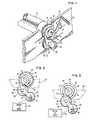
- Figure 1 illustrates the relevant portions of the gear drive chain and idler gear support member of the drive mechanism of the invention.
- Figure 2 illustrates an end view of the platen and its drive chain together with the constraining member and the bifurcated support member engaged to position the idler gear with a large diameter plate gear.
- Figure 3 illustrates the same apparatus as figure 2 with the constraining members sized to position the bifurcated support member and idler gear for engagement with a smaller diameter platen gear.
- The advantage of operator interchangeable platens in a gear driven line feed arrangement is provided by a typewriter or printer which has a shiftable idler gear engageable with the platen gear.
Platen 10 is typically provided with aplaten shaft 12 upon which agear 14 is fixedly mounted. The driven rotation ofgear 14 will rotateplaten shaft 12 andplaten 10. -
Frame 24 is provided with a support (not shown) of conventional form to support theplaten shaft 12 in a fixed spatial relation to the typewriter and, hence, the printing zone.Frame 24 further provides the necessary support for the drive chain comprisingdrive gear 28,shaft 36,support member 32,idler gear platen shaft 12, either fixed to rotate with theplaten shaft 12 or such that it is free to rotate with respect toplaten shaft 12, is constrainingmember member segment platen shaft 12. If this be the case, the ability to rotate with respect toshaft 12 is of minimal importance. The radius of the constrainingsegments bifurcations support member 32 will be separated from the axis of theplaten shaft 12 and thereby defines the spatial position ofidler gear shaft 34. The latter is attached to supportmember 32 which, in turn, is pivotally mounted onshaft 36.Bifurcations segments segment 16 will be engaged by engaging surface onbifurcation 33 of the bifurcatedsupport member 32. Similarly, the engaging surface onbirfucation 35 engages the periphery of thesegment 18. The radii ofsegments support member 32. By defining the position occupied bysupport member 32,shaft 34 and henceidler gear segments platen shaft 12. Also engageable withplaten gear 14 is detent arm 20 which is spring biased bytension spring 22. Detent arm 20 will act to repeatably positiongear 14 such that return to a particular line may be accomplished accurately. Referring now to Figure 3, the radius of constraining segments 16' and 18' have been altered to causeidler gear 28 to accommodate aplaten gear 14" reduced diameter and hence a reduced number of gear teeth. By reducing the number of gear teeth, the increment of feed for each indexing operation will be larger for a smaller platen gear diameter. - Idler
gear gear 14. Constrainingsegments platen shaft 12 andplaten 10, are inserted into the typewriter or printer, the surfaces of thesesegments member 32 into its appropriate position by engaging the engagement surfaces ofbifurcations - Referring again to Figure 1, it can be readily seen that
bifurcation 35 ofsupport member 32 is offset from the plane in whichbifurcation 33 extends. This deformation ofbifurcation 35 permits the engaging surface thereof to be axially offset thereby insuring the ability to clear constrainingsegment 16 to engage constrainingsegment 18 when the latter is of a smaller diameter than the diameter ofsegment 16. - It should be recognized that, alternatively, constraining members configured to approximate a wedge shape of the appropriate angular formation with the mounting hole formed at a precisely predetermined location for engagement with
platen shaft 12 may be substitutable for the concentric cams which form the constrainingsegments - As
platen 10 with itsshaft 12,gear 14 and constrainingmembers frame 24, constrainingmembers bifurcations member 32 aboutshaft 36. The rotation under the cam control will moveidler gear assembly gear 30 withplaten gear 14. Constrainingmembers gear 30 fromgear 14 under heavy loads inasmuch asgear 30 cannot move aboutdrive gear 28 so long as constrainingmembers bifurcations - Once
shaft 12 is completely seated in supportingframe 24, the constraining members will then act as a rigid cam to prevent the engagement surfaces onbifurcations drive 40 as illustrated schematically in Figures 2 and 3 inasmuch as a detailed description of their operation is not necessarily to understand the invention. - The above-disclosed arrangement makes it possible for the operator to change the platen to provide a different line feed increment where a gear of predetermined tooth pitch is fixedly mounted to the shaft of the platen, without requiring the services of a trained repairman or technician to make adjustments to the position of
idler gear
Claims (8)
Applications Claiming Priority (2)
| Application Number | Priority Date | Filing Date | Title |
|---|---|---|---|
| US06/273,556 US4347009A (en) | 1981-06-16 | 1981-06-16 | Operator interchangeable gear driven platen and platen drive mechanism for typewriters and printers |
| US273556 | 1981-06-16 |
Publications (2)
| Publication Number | Publication Date |
|---|---|
| EP0067289A1 EP0067289A1 (en) | 1982-12-22 |
| EP0067289B1 true EP0067289B1 (en) | 1984-11-14 |
Family
ID=23044428
Family Applications (1)
| Application Number | Title | Priority Date | Filing Date |
|---|---|---|---|
| EP82103333A Expired EP0067289B1 (en) | 1981-06-16 | 1982-04-21 | Mechanism for driving operator interchangeable gear driven platens in typewriters or printers |
Country Status (6)
| Country | Link |
|---|---|
| US (1) | US4347009A (en) |
| EP (1) | EP0067289B1 (en) |
| JP (1) | JPS57208287A (en) |
| BR (1) | BR8203396A (en) |
| CA (1) | CA1158587A (en) |
| DE (1) | DE3261226D1 (en) |
Families Citing this family (9)
| Publication number | Priority date | Publication date | Assignee | Title |
|---|---|---|---|---|
| US4470348A (en) * | 1982-05-25 | 1984-09-11 | Burroughs Corporation | Printer-processor system |
| JPS60151U (en) * | 1983-06-17 | 1985-01-05 | 蛇の目ミシン工業株式会社 | Attaching and detaching structure of platen body in printer |
| US4671686A (en) * | 1985-12-11 | 1987-06-09 | International Business Machines Corporation | Printer having removable paper feed module |
| US6070482A (en) * | 1997-04-21 | 2000-06-06 | Nidec Copal Corporation | Gear module |
| US5960671A (en) * | 1997-09-30 | 1999-10-05 | Philadelphia Gear Corp. | Eccentric pivotable mounting for changing gear reduction ratios |
| US6890055B2 (en) * | 2002-05-31 | 2005-05-10 | Hewlett-Packard Development Company, L.P. | Power transmission arrangement |
| TWI245544B (en) * | 2004-07-06 | 2005-12-11 | Avision Inc | Transmission drive with switchable gear ratios |
| US7234369B2 (en) * | 2004-12-03 | 2007-06-26 | Georg Bartosch | Continuously adjustable self-lubricating mill roll drive |
| US7926935B2 (en) * | 2007-01-19 | 2011-04-19 | Hewlett-Packard Development Company, L.P. | Print media support system and method |
Family Cites Families (7)
| Publication number | Priority date | Publication date | Assignee | Title |
|---|---|---|---|---|
| US2919783A (en) * | 1956-07-16 | 1960-01-05 | Standard Register Co | Strip feeding device |
| US3587811A (en) * | 1967-12-06 | 1971-06-28 | Singer Co | Platen power drive for line spacing,vertical tabulation and form-feed spacing |
| US3670981A (en) * | 1970-02-17 | 1972-06-20 | Datadyne Corp | Self-reversing ribbon drive |
| US3761000A (en) * | 1972-08-31 | 1973-09-25 | Teletype Corp | Web metering mechanism |
| US4133216A (en) * | 1977-12-16 | 1979-01-09 | Vamco Machine & Tool, Inc. | Gear support assembly |
| DE2836377C3 (en) * | 1978-08-19 | 1981-09-17 | Zahnradfabrik Friedrichshafen Ag, 7990 Friedrichshafen | Gear change transmission with several countershafts |
| US4347006A (en) * | 1980-12-01 | 1982-08-31 | International Business Machines Corporation | Paper insert and line feed mechanism |
-
1981
- 1981-06-16 US US06/273,556 patent/US4347009A/en not_active Expired - Fee Related
-
1982
- 1982-03-18 JP JP57041828A patent/JPS57208287A/en active Granted
- 1982-04-21 DE DE8282103333T patent/DE3261226D1/en not_active Expired
- 1982-04-21 EP EP82103333A patent/EP0067289B1/en not_active Expired
- 1982-05-18 CA CA000403221A patent/CA1158587A/en not_active Expired
- 1982-06-09 BR BR8203396A patent/BR8203396A/en not_active IP Right Cessation
Also Published As
| Publication number | Publication date |
|---|---|
| US4347009A (en) | 1982-08-31 |
| JPS57208287A (en) | 1982-12-21 |
| EP0067289A1 (en) | 1982-12-22 |
| JPS6316274B2 (en) | 1988-04-08 |
| CA1158587A (en) | 1983-12-13 |
| BR8203396A (en) | 1983-05-31 |
| DE3261226D1 (en) | 1984-12-20 |
Similar Documents
| Publication | Publication Date | Title |
|---|---|---|
| EP0067289B1 (en) | Mechanism for driving operator interchangeable gear driven platens in typewriters or printers | |
| US4607517A (en) | Stamping and bending tool assembly | |
| US3880016A (en) | Variable displacement apparatus for platen and tractor feed | |
| EP0103016A1 (en) | Improvements relating to printers | |
| JPH0418558B2 (en) | ||
| DE3222845C2 (en) | Printing mechanism for a typewriter or a printer | |
| EP0038283B1 (en) | Matrix printing machine with adjustable printing head allowing adjustment of the printing rift | |
| EP0053758B1 (en) | Powered paper feed mechanism for a typewriter or the like | |
| JPH0611578B2 (en) | Color printer | |
| US5106216A (en) | Device for driving a platen and carriage of a printing machine | |
| EP0212573A1 (en) | Printer of automatic type-wheel exchanging type | |
| GB1584136A (en) | System for positioning a type carrier | |
| EP0795412B1 (en) | Single motor and drive shaft with several worms for a printer | |
| DE3805209A1 (en) | Device for the remote actuation and numerical control of the precise fine adjustments of the position of a flexographic inking unit | |
| US4285605A (en) | Escapement mechanism and backspace mechanism for a moving paper carriage typewriter having dual pitch capability | |
| US4632581A (en) | Serial printer having trigger mechanism | |
| EP0386672A2 (en) | Printer having an ink ribbon shift apparatus | |
| US4710046A (en) | Platen clutch mechanism | |
| US4778294A (en) | Printer | |
| US4105106A (en) | Typewriter platen clutch mechanism | |
| JPS61270184A (en) | Ribbon-shifting device for printer | |
| JP2963616B2 (en) | Printing equipment ribbon drive | |
| US4614155A (en) | Mechanism for adjusting the vertical position of a format on a printer | |
| US3647356A (en) | Printer drive with page record feed | |
| SU1013207A1 (en) | Feeding device |
Legal Events
| Date | Code | Title | Description |
|---|---|---|---|
| PUAI | Public reference made under article 153(3) epc to a published international application that has entered the european phase |
Free format text: ORIGINAL CODE: 0009012 |
|
| AK | Designated contracting states |
Designated state(s): DE FR GB IT |
|
| 17P | Request for examination filed |
Effective date: 19830420 |
|
| GRAA | (expected) grant |
Free format text: ORIGINAL CODE: 0009210 |
|
| AK | Designated contracting states |
Designated state(s): DE FR GB IT |
|
| PG25 | Lapsed in a contracting state [announced via postgrant information from national office to epo] |
Ref country code: IT Free format text: LAPSE BECAUSE OF FAILURE TO SUBMIT A TRANSLATION OF THE DESCRIPTION OR TO PAY THE FEE WITHIN THE PRESCRIBED TIME-LIMIT;WARNING: LAPSES OF ITALIAN PATENTS WITH EFFECTIVE DATE BEFORE 2007 MAY HAVE OCCURRED AT ANY TIME BEFORE 2007. THE CORRECT EFFECTIVE DATE MAY BE DIFFERENT FROM THE ONE RECORDED. Effective date: 19841114 |
|
| REF | Corresponds to: |
Ref document number: 3261226 Country of ref document: DE Date of ref document: 19841220 |
|
| ET | Fr: translation filed | ||
| PLBE | No opposition filed within time limit |
Free format text: ORIGINAL CODE: 0009261 |
|
| STAA | Information on the status of an ep patent application or granted ep patent |
Free format text: STATUS: NO OPPOSITION FILED WITHIN TIME LIMIT |
|
| 26N | No opposition filed | ||
| PGFP | Annual fee paid to national office [announced via postgrant information from national office to epo] |
Ref country code: FR Payment date: 19890324 Year of fee payment: 8 |
|
| PGFP | Annual fee paid to national office [announced via postgrant information from national office to epo] |
Ref country code: GB Payment date: 19890331 Year of fee payment: 8 |
|
| PGFP | Annual fee paid to national office [announced via postgrant information from national office to epo] |
Ref country code: DE Payment date: 19890505 Year of fee payment: 8 |
|
| PG25 | Lapsed in a contracting state [announced via postgrant information from national office to epo] |
Ref country code: GB Effective date: 19900421 |
|
| GBPC | Gb: european patent ceased through non-payment of renewal fee | ||
| PG25 | Lapsed in a contracting state [announced via postgrant information from national office to epo] |
Ref country code: FR Effective date: 19901228 |
|
| PG25 | Lapsed in a contracting state [announced via postgrant information from national office to epo] |
Ref country code: DE Effective date: 19910101 |
|
| REG | Reference to a national code |
Ref country code: FR Ref legal event code: ST |