EP0067198B1 - Cylinder with sliding piston - Google Patents
Cylinder with sliding piston Download PDFInfo
- Publication number
- EP0067198B1 EP0067198B1 EP82900191A EP82900191A EP0067198B1 EP 0067198 B1 EP0067198 B1 EP 0067198B1 EP 82900191 A EP82900191 A EP 82900191A EP 82900191 A EP82900191 A EP 82900191A EP 0067198 B1 EP0067198 B1 EP 0067198B1
- Authority
- EP
- European Patent Office
- Prior art keywords
- piston
- cylinder
- bearing
- shaft
- motion
- Prior art date
- Legal status (The legal status is an assumption and is not a legal conclusion. Google has not performed a legal analysis and makes no representation as to the accuracy of the status listed.)
- Expired
Links
Images
Classifications
-
- F—MECHANICAL ENGINEERING; LIGHTING; HEATING; WEAPONS; BLASTING
- F16—ENGINEERING ELEMENTS AND UNITS; GENERAL MEASURES FOR PRODUCING AND MAINTAINING EFFECTIVE FUNCTIONING OF MACHINES OR INSTALLATIONS; THERMAL INSULATION IN GENERAL
- F16J—PISTONS; CYLINDERS; SEALINGS
- F16J10/00—Engine or like cylinders; Features of hollow, e.g. cylindrical, bodies in general
- F16J10/02—Cylinders designed to receive moving pistons or plungers
Abstract
Description
- The present invention relates to a lubricated cylinder having a bearing at one end and a piston mounted on a shaft, the piston being slidably located within the cylinder and the shaft being slidably located in the bearing.
- In conventional sliding mechanical joints which move e.g. in reciprocation substantially in a straight line, the axes of the bearings or the bearing surfaces are generally parallel with the axis of motion. Conventional joints are efficient when the resultant of the received or transmitted forces is substantially parallel to the direction of relative motion.
- This situation however is extremely rare in practice. As a rule, either occasionally or permanently, the joint has to withstand considerable forces having a component perpendicular to the direction of motion. The results may be increased wear on the parts in contact resulting in gaps and lower geometrical accuracy of relative motion, and a coefficient of friction which results in an oppositing force which wastes power.
- There is also a serious risk of seizure under heavy lateral loads.
- It is an object of the present invention to obviate these disadvantages or at least delay or reduce the aforementioned harmful effects (i.e. opposing force, wear, power consumption and seizure) in the case where operation occurs in the presence of oil or, more generally, in the presence of a fluid.
- FR-A-1001088 and US-A-2284645 both show compressors having a piston reciprocating within a cylinder, driven by an offset rotating shaft. This results in the piston shaft being subjected to lateral forces as well as axial forces. However, in each case the stroke of the piston is small compared to the cylinder bore and so the piston is allowed to rock as it travels along its stroke. In both cases, the piston shaft is not supported by a bearing.
- In the case of FR-A-1001088, the piston surface is slightly convex whereas in the case of US-A-2284645 the piston surface is made up of resilient pads, thus in each case the rocking of the piston can be accommodated.
- According to the invention the cylinder and piston arrangement is characterised in that the bearing has a surface which is convex in the axial direction and in that the bearing is offset from the axis of the cylinder in a direction opposite to that of the lateral force, whereby when the piston slides in the cylinder a rotation or tilting is imposed on the shaft and piston, about an axis substantially perpendicular to the direction of the main motion of the shaft and piston and to the direction of the lateral force.
- Preferably, the surface of the piston is convex in the axial direction. As a result of the secondary rotation, the various surfaces may be in contact at points or lines which vary during motion, so local wear can be avoided. Furthermore, if these surfaces are not flattened but curved, they may have a shape which facilitates the formation of an "oil wedge" during motion. This produces a hydrodynamic force which can separate the two surfaces and prevent permanent direct contact between them.
- In a preferred mode of operation, the secondary rotation is such that, during the motion, it acts so as to "close" the oil wedge in the immediate vicinity of the two surfaces in contact.
- This method may result in the following advantages:-
- 1. Improved efficiency of the materials in contact, avoiding seizure;
- 2. Distribution of wear over a larger area;
- 3. Reduction of energy consumption;
- 4. Positive lift during reversal of direction of motion; and
- 5. Lower opposing force during reversals, thus reducing the associated "impact".
- The amplitude of rotation during the entire reciprocating travel is small, usually between 5 and 150 x 10-4 radian (0.5 and 15 thousandth of a radian).
- Thus, since the moving parts preferably bear on a counteracting part by means of at least one bearing surface whose profile is a curved convex surface in the longitudinal direction (parallel to the motion in a straight line), the point (or line) of contact moves with the moving part. The curved surfaces can be present from the beginning or can be produced during initial use of the joint (running-in).
- The curved surface could have any shape (actually the envelope of the positions of the outer surface of one of the moving parts of the other), however, for practical reasons, it is usually an arc of an ellipse or circle having a large radius or radii or curvature.
- The secondary rotation is brought about simply by moving the bearing out of centre by a certain amount relative to the axial geometrical position. The out-of-centre position is preferably in the plane defined by the direction of lateral forces and the main axis of motion along a straight line.
- Preferably therefore the shaft is displaced to the side of the axis opposite to the point of contact between the shaft and the bearing, and may result from the lateral forces acting on the moving part.
- The invention may be carried into practice in various ways and some embodiments will now be described by way of example with reference to the accompanying drawings, in which:-
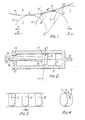
- Figure 1 is a diagrammatic representation of the relative motion of two components to illustrate the principle of the invention;
- Figure 2 is a partial longitudinal section through a jack or actuator in accordance with the invention; for clarity in the drawing, the eccentricity and clearances have been greatly exaggerated;
- Figures 3 and 4 show diagrammatically the theoretical lines of contact between the piston and cylinder of Figure 2 during motion; and
- Figure 4 is a section through a test device.
- In Figure 1, a moving
member 1 bounded by its convexouter surface 2 moves in a main rectilinear direction T relative to astationary member 3 having an outer surface 4. During the rectilinear motion T,member 1 also undergoes rotation R. During the motion, points A, B, C onsurface 2 of the movingmember 1 move respectively and in succession to points A, B" C2, spaced apart on the outer surface 4 in the direction of motion T. Consequently, an oil wedge, diagrammatically shown at 5 forms between the twomembers oil wedge 5 tends to close during the motion. - If the main motion occurs in the opposite direction T' a similar oil wedge 5' tends to form and to close as a result of secondary rotation R' in the reverse direction. Thus, the effect is observed if rotation R or R' occurs in either direction.
- Figure 2 shows a jack or shock-absorber device. It comprises a
cylinder 11 having anaxis 12 and abearing 13 whoseaxis 14 is out of centre by an amount e relative to the axis of thecylinder 12. The device also comprises apiston 15 in thecylinder 11, thepiston 15 being centred on ashaft 16 borne by thebearing 13. When theshaft 16 is subjected to lateral bending, thepiston 15 bears against thecylinder surface 17 to one side of theaxis 12 and theshaft 16 bears against thesurface 18 of thebearing 13 to the opposite side of theaxis 12. - The eccentricity e is in the plane defined by the theoretical point of contact between the piston and cylinder and the
cylinder axis 12, and is preferably displaced from theaxis 12 in a direction away from thesurface 18 where theshaft 16 bears on thebearing 13. - The
outer surface 17 of thepiston 15 is, in the longitudinal direction, an arc of a circle having a radius r which is usually much greater than the diameter d of thecylinder 11. By way of example, in a cylinder 40 mm in diameter with a piston stroke I = ±90 mm relative to the central position and an eccentricity e of 0.25 mm, r can vary from 5 to 20 m. - If the
piston 15 is out of centre by a distance e' which is in the same direction from theaxis 12 as e, then the situation will be quite acceptable provided e ≠ e'. - As shown in Figures 3 and 4, the theoretical curve of contact between the piston and cylinder moves during the motion T through positions I, II and Ill. It is thus possible to bring about and maintain hydrodynamic conditions and thus reduce wear. Similar conditions occur at the
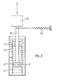
bearing 13. - Tests were carried out on a device as shown in Figure 5. The device comprised a
piston 15, 40 mm in diameter and 18 mm thick in acylinder 11 filled with oil which was free to move throughapertures 21 formed in the cylinder wall and in thepiston 15. - The piston-
rod 16 was 20 mm in diameter and was connected to a crank-connection rod system via a force pick-up 20. The piston was driven by this system in reciprocating motion having a period of one second and an amplitude of ±60 mm. Therod 16 extended through an 18 mmthick guide 13. A transverse force of 500 N was applied by acalibrated spring 22, at a distance of 300 mm from the central axis of thepiston 15. - The distance of the guide from the piston in its central position was 150 mm.
- When the guide and piston were centred and had cylindrical bearing surfaces, the average coefficient of friction during the cycle was found to be 5% and the instantaneous coefficient during reversal was 8%.
- In a device according to the invention made of the same materials, except that the guide was 0.2 mm out of centre and the guide and piston had a convexity of r = 12 m, the coefficients of friction were found to be reduced to 3 and 4% respectively.
Claims (4)
Priority Applications (1)
| Application Number | Priority Date | Filing Date | Title |
|---|---|---|---|
| AT82900191T ATE13218T1 (en) | 1980-12-23 | 1981-12-23 | CYLINDER WITH SLIDING PISTON. |
Applications Claiming Priority (2)
| Application Number | Priority Date | Filing Date | Title |
|---|---|---|---|
| FR8027830A FR2496787A1 (en) | 1980-12-23 | 1980-12-23 | METHOD AND DEVICE FOR REDUCING FRICTION AND IMPROVING THE RESISTANCE TO WEAR AND BINDING OF LUBRICATED SLIDING MECHANICAL LINKS |
| FR8027830 | 1980-12-23 |
Publications (2)
| Publication Number | Publication Date |
|---|---|
| EP0067198A1 EP0067198A1 (en) | 1982-12-22 |
| EP0067198B1 true EP0067198B1 (en) | 1985-05-08 |
Family
ID=9249648
Family Applications (1)
| Application Number | Title | Priority Date | Filing Date |
|---|---|---|---|
| EP82900191A Expired EP0067198B1 (en) | 1980-12-23 | 1981-12-23 | Cylinder with sliding piston |
Country Status (6)
| Country | Link |
|---|---|
| EP (1) | EP0067198B1 (en) |
| JP (1) | JPS58500078A (en) |
| AT (1) | ATE13218T1 (en) |
| DE (1) | DE3170449D1 (en) |
| FR (1) | FR2496787A1 (en) |
| WO (1) | WO1982002234A1 (en) |
Families Citing this family (2)
| Publication number | Priority date | Publication date | Assignee | Title |
|---|---|---|---|---|
| GB8810553D0 (en) * | 1988-05-05 | 1988-06-08 | Smith D W | Integrated hydraulic pedal |
| JP5665030B2 (en) * | 2011-04-27 | 2015-02-04 | Smc株式会社 | Wear ring used in linear actuator |
Family Cites Families (4)
| Publication number | Priority date | Publication date | Assignee | Title |
|---|---|---|---|---|
| GB529885A (en) * | 1939-06-10 | 1940-11-29 | Edward Cuthbert Lee | Pistons and cylinders for varied uses |
| US2284645A (en) * | 1941-01-27 | 1942-06-02 | Duffy Charles Hugh | Air pump or compressor |
| FR1001088A (en) * | 1949-12-08 | 1952-02-19 | S E P A | Spherical piston refrigeration compressor and mechanical applications of the spherical piston |
| CA938225A (en) * | 1971-07-19 | 1973-12-11 | D. Guenther William | Four stroke hybrid engine |
-
1980
- 1980-12-23 FR FR8027830A patent/FR2496787A1/en active Granted
-
1981
- 1981-12-23 EP EP82900191A patent/EP0067198B1/en not_active Expired
- 1981-12-23 DE DE8282900191T patent/DE3170449D1/en not_active Expired
- 1981-12-23 WO PCT/GB1981/000284 patent/WO1982002234A1/en active IP Right Grant
- 1981-12-23 AT AT82900191T patent/ATE13218T1/en not_active IP Right Cessation
- 1981-12-23 JP JP50025182A patent/JPS58500078A/en active Pending
Also Published As
| Publication number | Publication date |
|---|---|
| JPS58500078A (en) | 1983-01-13 |
| WO1982002234A1 (en) | 1982-07-08 |
| ATE13218T1 (en) | 1985-05-15 |
| FR2496787A1 (en) | 1982-06-25 |
| DE3170449D1 (en) | 1985-06-13 |
| EP0067198A1 (en) | 1982-12-22 |
| FR2496787B1 (en) | 1985-01-18 |
Similar Documents
| Publication | Publication Date | Title |
|---|---|---|
| US4246833A (en) | High pressure spherical piston | |
| US5494135A (en) | Lubrication system for a conjugate drive mechanism | |
| US3659502A (en) | Reciprocating engines | |
| EP0067198B1 (en) | Cylinder with sliding piston | |
| US9714589B2 (en) | Crankshaft for an alternative cooling compressor | |
| EP0410074B1 (en) | Radial load reducing device, and sliding bearing and screw compressor using the device | |
| US4688439A (en) | Wabble plate engine mechansim | |
| US3836158A (en) | Packing ring | |
| US5513541A (en) | Conjugate drive mechanism | |
| EP0154405B1 (en) | Piston for reciprocating engine | |
| EP0069175A1 (en) | Piston for an internal combustion engine | |
| CN107575378B (en) | Adjustable inner curve hydraulic pump or motor | |
| US6082313A (en) | Power machine lubrication | |
| CN210195965U (en) | Guide ring structure | |
| SU1643834A1 (en) | Shaft seal | |
| CN107035681B (en) | Plunger, plunger pump and hydraulic device | |
| CN111237153B (en) | Axial plunger pump plunger with stepped multiple grooves | |
| CN110894850B (en) | Bearing with bearing pin for use in engines and other devices | |
| SU1638361A1 (en) | Piston and connecting rod assembly of axial piston hydraulic machine | |
| SU1703847A1 (en) | Sealing of cylinder-and-piston group of piston machine | |
| SU1709135A1 (en) | Bearing assembly | |
| EP0398632A2 (en) | Hydraulic piston and cylinder arrangement | |
| WO2003093701A1 (en) | A connection assembly for converting between reciprocal and rotary motion | |
| SU1409779A1 (en) | Piston compressor with contactless piston seal | |
| RU2000441C1 (en) | Swash-plate engine |
Legal Events
| Date | Code | Title | Description |
|---|---|---|---|
| PUAI | Public reference made under article 153(3) epc to a published international application that has entered the european phase |
Free format text: ORIGINAL CODE: 0009012 |
|
| 17P | Request for examination filed |
Effective date: 19820805 |
|
| AK | Designated contracting states |
Designated state(s): AT DE GB SE |
|
| GRAA | (expected) grant |
Free format text: ORIGINAL CODE: 0009210 |
|
| AK | Designated contracting states |
Designated state(s): AT DE GB SE |
|
| REF | Corresponds to: |
Ref document number: 13218 Country of ref document: AT Date of ref document: 19850515 Kind code of ref document: T |
|
| REF | Corresponds to: |
Ref document number: 3170449 Country of ref document: DE Date of ref document: 19850613 |
|
| PLBE | No opposition filed within time limit |
Free format text: ORIGINAL CODE: 0009261 |
|
| STAA | Information on the status of an ep patent application or granted ep patent |
Free format text: STATUS: NO OPPOSITION FILED WITHIN TIME LIMIT |
|
| 26N | No opposition filed | ||
| PGFP | Annual fee paid to national office [announced via postgrant information from national office to epo] |
Ref country code: AT Payment date: 19861110 Year of fee payment: 6 |
|
| PG25 | Lapsed in a contracting state [announced via postgrant information from national office to epo] |
Ref country code: GB Effective date: 19881223 Ref country code: AT Effective date: 19881223 |
|
| PG25 | Lapsed in a contracting state [announced via postgrant information from national office to epo] |
Ref country code: SE Effective date: 19881224 |
|
| GBPC | Gb: european patent ceased through non-payment of renewal fee | ||
| PG25 | Lapsed in a contracting state [announced via postgrant information from national office to epo] |
Ref country code: DE Effective date: 19890901 |
|
| EUG | Se: european patent has lapsed |
Ref document number: 82900191.6 Effective date: 19891205 |