EP0066695A2 - Appareil de compactage de combustible nucléaire irradié - Google Patents
Appareil de compactage de combustible nucléaire irradié Download PDFInfo
- Publication number
- EP0066695A2 EP0066695A2 EP19820103199 EP82103199A EP0066695A2 EP 0066695 A2 EP0066695 A2 EP 0066695A2 EP 19820103199 EP19820103199 EP 19820103199 EP 82103199 A EP82103199 A EP 82103199A EP 0066695 A2 EP0066695 A2 EP 0066695A2
- Authority
- EP
- European Patent Office
- Prior art keywords
- fuel rods
- fuel
- consolidation
- rods
- station
- Prior art date
- Legal status (The legal status is an assumption and is not a legal conclusion. Google has not performed a legal analysis and makes no representation as to the accuracy of the status listed.)
- Granted
Links
Images


Classifications
-
- G—PHYSICS
- G21—NUCLEAR PHYSICS; NUCLEAR ENGINEERING
- G21C—NUCLEAR REACTORS
- G21C19/00—Arrangements for treating, for handling, or for facilitating the handling of, fuel or other materials which are used within the reactor, e.g. within its pressure vessel
- G21C19/32—Apparatus for removing radioactive objects or materials from the reactor discharge area, e.g. to a storage place; Apparatus for handling radioactive objects or materials within a storage place or removing them therefrom
-
- G—PHYSICS
- G21—NUCLEAR PHYSICS; NUCLEAR ENGINEERING
- G21C—NUCLEAR REACTORS
- G21C19/00—Arrangements for treating, for handling, or for facilitating the handling of, fuel or other materials which are used within the reactor, e.g. within its pressure vessel
- G21C19/02—Details of handling arrangements
- G21C19/06—Magazines for holding fuel elements or control elements
-
- G—PHYSICS
- G21—NUCLEAR PHYSICS; NUCLEAR ENGINEERING
- G21C—NUCLEAR REACTORS
- G21C19/00—Arrangements for treating, for handling, or for facilitating the handling of, fuel or other materials which are used within the reactor, e.g. within its pressure vessel
- G21C19/34—Apparatus or processes for dismantling nuclear fuel, e.g. before reprocessing ; Apparatus or processes for dismantling strings of spent fuel elements
-
- Y—GENERAL TAGGING OF NEW TECHNOLOGICAL DEVELOPMENTS; GENERAL TAGGING OF CROSS-SECTIONAL TECHNOLOGIES SPANNING OVER SEVERAL SECTIONS OF THE IPC; TECHNICAL SUBJECTS COVERED BY FORMER USPC CROSS-REFERENCE ART COLLECTIONS [XRACs] AND DIGESTS
- Y02—TECHNOLOGIES OR APPLICATIONS FOR MITIGATION OR ADAPTATION AGAINST CLIMATE CHANGE
- Y02E—REDUCTION OF GREENHOUSE GAS [GHG] EMISSIONS, RELATED TO ENERGY GENERATION, TRANSMISSION OR DISTRIBUTION
- Y02E30/00—Energy generation of nuclear origin
- Y02E30/30—Nuclear fission reactors
-
- Y—GENERAL TAGGING OF NEW TECHNOLOGICAL DEVELOPMENTS; GENERAL TAGGING OF CROSS-SECTIONAL TECHNOLOGIES SPANNING OVER SEVERAL SECTIONS OF THE IPC; TECHNICAL SUBJECTS COVERED BY FORMER USPC CROSS-REFERENCE ART COLLECTIONS [XRACs] AND DIGESTS
- Y02—TECHNOLOGIES OR APPLICATIONS FOR MITIGATION OR ADAPTATION AGAINST CLIMATE CHANGE
- Y02W—CLIMATE CHANGE MITIGATION TECHNOLOGIES RELATED TO WASTEWATER TREATMENT OR WASTE MANAGEMENT
- Y02W30/00—Technologies for solid waste management
- Y02W30/50—Reuse, recycling or recovery technologies
Definitions
- This invention relates to storage of nuclear fuel assemblies and more particularly to the consolidation and storage of spent nuclear fuel rods in a relatively small storage area.
- the fuel assemblies comprising the core of the nuclear reactor must be rearranged with the depleted or spent fuel assemblies being replaced with fresh ones.
- the spent fuel assemblies are removed from the reactor vessel and generally stored in a pool of water on the reactor site. Since a conventional fuel assembly comprises structure other than fuel rods such as grids and control rod guide tubes, a spent fuel assembly occupies more space in the storage pool than would be required for the individual fuel rods. Because the storage pool has a finite volume it would be desirable to be able to store the fuel rods in a closely packed array and with a minimum of support structure to thereby maximize the amount of spent nuclear fuel that can be stored in a given volume of the storage pool. This would provide a greater storage capacity for the spent fuel rods until the fuel rods are transported off the reactor site for storage or reprocessing.
- the radioactive nature of the spent fuel assemblies increases the difficulty of not only transporting the spent fuel assembly but of also dismantling the fuel assembly.
- the present invention resides in an apparatus for remotely consolidating nuclear fuel rods taken from fuel assemblies in which the fuel rods are supported spaced from each other in first and second perpendicular directions, characterized by row ordering means arranged to accept a plurality of nuclear fuel rods for rearranging said fuel rods into a different configuration, first consolidation means associated with said row ordering means for compacting individual rows of said fuel rods in said first direction, and second consolidation means associated with said row ordering means for compacting said fuel rods in said second direction.
- the invention described herein provides a system for removing the fuel rods from the fuel assembly and for remotely rearranging the fuel rods in a consolidated fashion.
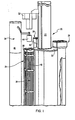
- the spent fuel consolidation system comprises a rotatable platform 20 that is capable of rotating about its vertical axis under the influence of a drive system (not shown) and that is capable of operating while completely submerged in a fluid such as water.
- Platform 20 comprises a vertical support 22, a fuel assembly station 24, consolidation station 26 and canister station 28.
- Fuel assembly station 24, consolidation station 26, and canister station 28 are attached to support plate 30 which is rotatably attached to vertical support 22.
- Support plate 30 is arranged such that when it is rotated about vertical support 22, fuel assembly station 24, consolidation station 26 and canister station 28 may be selectively positioned with respect to gripper mechanism 32 which is slidably mounted on vertical support 22.
- a nozzle removal mechanism 34 is also arranged near platform 20 for removing top nozzle 36 from fuel assembly 38.
- Fuel assembly 38 may be one such as that described in United States Patent No. 3,791,466 issued February 12, 1974 in the name of J. F. Patterson et al.
- fuel assembly station 24 provides a station for holding spent fuel assembly 38 while top nozzle 36 and spent fuel rods 40 are removed therefrom.
- Fuel rods 40 are generally cylindrical metallic tubes containing nuclear fuel as is well understood in the art.
- Consolidation station 26 provides a station for rearranging fuel rods 40 into a closely packed configuration without the need for the remainder of the fuel assembly support structure.
- Canister station 28 provides a station for locating a canister 42 for accepting and holding fuel rods 40 after fuel rods 40 have been consolidated by consolidation station 26.
- nozzle removal mechanism 34 comprises an internal cutter mechanism 44 that is slidably mounted on positioning mechanism 46.
- Internal cutter mechanism 44 may comprise a drive mechanism 48 with a plurality of internal cutters 50 connected thereto.
- Positioning mechanism 46 serves to position internal cutter mechanism 44 over fuel assembly 38 of fuel assembly station 24. Since the typical fuel assembly 38 comprises a top nozzle 36 which is attached to a plurality of control rod guide tubes 52, it is necessary to cut control rod guide tubes 52 so that the upper portion of control rod guide tubes 52 and top nozzle 36 may be removed to expose the top ends of the spent fuel rods 40.
- internal cutter mechanism 44 is lowered onto top nozzle 36 by positioning mechanism 46, an internal cutter 50 is slid into each control rod guide tube 52.
- drive mechanism 48 is activated which causes each internal cutter 50 to rotate in each control rod guide tube 52 and to sever the top section of each control rod guide tube 52 from the remainder of the control rod guide tube.
- Positioning mechanism 46 then removes internal cutter mechanism 44 from top nozzle 36.
- gripper mechanism 32 may comprise a metal first plate 56, a metal second plate 58 and a flexible member 50 disposed therebetween.
- First plate 56 may be connected to a rod 62 that is disposed through second plate 58 and flexible member 60 and is connected to an hydraulic cylinder 64.
- First plate 56, second plate 58, and flexible member 60 have holes therein for accommodating the insertion of fuel rods 40 such that when hydraulic cylinder 64 is activated first plate 56 and second plate 58 are drawn together thereby squeezing flexible member 60, which may be a rubber plate, into contact with fuel rods 40. In this manner, fuel rods 40 may be firmly gripped for removal from fuel assembly 38.
- top nozzle 36 has been removed from fuel assembly 38
- internal cutter mechanism 44 is moved away from fuel assembly station 24 and gripper mechanism 32 is moved downwardly along vertical member 22 and into contact with the exposed fuel rods 40 of fuel assembly 38.
- Gripper mechanism 32 then grips each fuel rod 40 as previously described. With gripper mechanism 32 gripping each fuel rod 40, gripper mechanism 32 is moved upwardly along vertical support 22. Since fuel assembly 38 is locked at its lower end to fuel assembly station 24, the upward pulling of fuel rods 40 by gripper mechanism 32 removes fuel rods 40 from the remainder of fuel assembly 38.
- a cage 66 which may have comb-like fingers may be attached to gripper mechanism 32 for maintaining the alignment of fuel rods 40 relative to each other. In this manner, fuel rods 40 can be removed from the remainder of fuel assembly 38.
- platform 20 may be rotated which will cause consolidation station 26 to be positioned under gripper mechanism 32 and fuel rods 40.
- gripper mechanism 32 is lowered along vertical support 22 so that fuel rods 40 are inserted into consolidation mechanism 70 of consolidation station 26.
- Consolidation mechanism 70 vertically and horizontal packs fuel rods 40 as fuel rods 40 are lowered into consolidation mechanism 70 thereby closely packing fuel rods 40.
- gripper mechanism 32 releases fuel rods 40 so that fuel rods 40 are completely contained in consolidation mechanism 70.
- gripper mechanism 32 by means of a conventional gripper (not shown), is caused to grip consolidation mechanism 70.
- consolidation mechanism 70 While holding consolidation mechanism 70, gripper mechanism 32 is again raised along vertical support 22 until consolidation mechanism 70 with the fuel rods 40 therein is raised clear of consolidation station 26. With consolidation mechanism 70 lifted clear of consolidation station 26, platform 20 is again rotated until canister station 28 is located under consolidation mechanism 70. When consolidation mechanism 70 is over canister station 28, gripper mechanism 32 is lowered thereby positioning consolidation mechansim 70 on a canister 72 of canister station 28. With consolidation mechanism 70 positioned on canister 72, the bottom end of consolidation mechanism 70 is remotely opened thereby depositing fuel rods 40 into canister 72 in a closely packed fashion. Each canister 72 may be arranged with a divider so that each canister 72 can hold more than one set of consolidated fuel rods 40. Once fuel rods 40 have been deposited in canister 72, consolidation mechanism 70 may be returned to consolidation station 26 by lifting consolidation mechanism 70 and rotating platform 20 in a reverse direction.
- the spent fuel consolidation system When consolidation mechanism 70 has been returned to consolidation station 26 and when the remainder of fuel assembly 38 has been removed from fuel assembly station 24, the spent fuel consolidation system is ready to accept an additional spent fuel assembly in fuel assembly station 24.
- the system may be used to consolidate several sets of fuel rods 40 into a smaller configuration and store them in a single canister, while the fuel rods are maintained underwater.
- the canister When a particular canister 72 is filled in this manner, the canister may be remotely moved to a spent fuel storage pool for further storage.
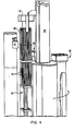
- consolidation mechanism 70 comprises a row ordering section 80, a horizontal consolidation section 82, and a vertical consolidation section 84.
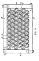
- Row ordering section 80 comprises a first frame 86 manufactured from a material such as aluminum for supporting an array of hollow guide tubes 88.
- Guide tubes 88 may be stainless steel tubes having a length of approximately 2 m and having an inside diameter of approximately 1.3 cm for accommodating the insertion of fuel rods 40.
- Guide tubes 88 are arranged in first frame 86 to conform to the same arrangement as fuel rods 40 have in a fuel assembly such that when fuel rods 40 are introduced into consolidation mechanism 70 by gripper mechanism 32 each fuel rod 40 slides into a separate guide tube 88.
- a plurality of plugs 90 are disposed between guide tubes 88 in a position to correspond to the positions of a fuel assembly that have no fuel rods such as control rod locations. Plugs 90 serve to maintain alignment of guide tubes 88 and to maintain a configuration corresponding to that of fuel rods 40 in a fuel assembly.
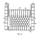
- Row ordering section 80 also comprises an aluminum second frame 92 for supporting the other end of guide tubes 88.
- guide tubes 88 are not arranged in second frame 92 in the same configuration as in first frame 86. Rather, some of guide tubes 88 may be slightly curved or bent so as to form a closely packed array of guide tubes 88 as shown in Figure 9. As can be seen from a comparison of Figures 8 and 9, guide tubes 88 extend from first frame 86 to second frame 92 but the ends of some of the guide tubes 88 are arranged in a different configuration in each of such frames.
- This arrangement of guide tubes 88 provides a means by which a set of fuel rods 40 having the same configuration as the fuel rods in a fuel assembly can be introduced in one end of guide tubes 88 and moved through guide tubes 88 to exit guide tubes 88 in a more closely packed array. It should be noted that not only does the configuration in second frame 92 eliminate plugs 90 but it may also transform the configuration of first frame 86 from a substantially square array to a substantially rectangular array. Of course, the particular array chosen for second frame 92 is primarily dependent on the configuration chosen for the final storage of fuel rods 40. Since the length of each fuel rod 40 exceeds the length of each guide tube 88, several of the fuel rods 40 may be slightly bent during its travel through guide tubes 88.
- fuel rods 40 can be moved through guide tubes 88 under mere gravitational force due to the weight of each fuel rod 40 or they may be pushed through guide tubes 88 without damage to the fuel rods 40.
- horizontal consolidation section 82 comprises a first housing 94 having a plurality of horizontal stainless steel plates 96 attached thereto defining a plurality of horizontal spaces 98 for accommodating fuel rods 40 as fuel rods 40 exit row ordering section 80.
- a plurality of spacers 100 are attached to first housing 94 and are disposed between plates 96 in spaces 98 for contacting the outermost fuel rod 40 in each space 98.
- the spacers 100 in alternate spaces 98 may be of different lengths for contacting the outermost fuel rod 40 based on the configuration of fuel rods 40 in each space 98.
- the ends of guide tubes 88 of row ordering section 80 are disposed in spaces 98 and between plates 96 at first end 102 of horizontal consolidation section 82 for introducing fuel rods 40 into the corresponding space 98.
- First housing 94 is arranged to have a longer width at first end 102 than at second end 104 so that as fuel rods 40 are moved therethrough, the outermost fuel rod 40 is moved inwardly by contacting spacers 100 thereby horizontally closely packing each horizontal row of fuel rods 40 while maintaining the vertical spacing between each horizontal row of fuel rods 40 by means of plates 96.
- horizontal consolidation section 82 provides a means to horizontally compact fuel rods 40 as they exit row ordering section 80.
- vertical consolidation section 84 comprises a second housing 106 attached to first housing 94 and arranged to support plates 96 which extend from first housing 94 into second housing 106.
- plates 96 are of different lengths so that the uppermost plates 96 are shorter than the lowermost plates 96 and with the intermediate plates 96 having a length longer than the uppermost plates 96 and shorter than the lowermost plates 96.
- each succeeding plate 96 is generally longer than the preceding one from top to bottom.
- a plurality of rollers 108 are mounted on second housing 106 and arranged to contact fuel rods 40 as fuel rods 40 exit plates 96.
- Rollers 108 are attached to second housing 106 at different elevations corresponding to the ends of plates 96 such that as a row of fuel rods 40 passes beyond the end of a plate 96, the fuel rods contact a roller 108 for maintaining the horizontal alignment of the fuel rods 40 and for slightly bending the fuel rods downwardly and into contact with the next row of fuel rods 40.
- Rollers 108 may be formed with grooves 110 for accommodating the shape of fuel rods 40 and for maintaining the horizontal alignment of fuel rods 40.
- vertical consolidation section 84 provides a means to vertically consolidate fuel rods 40 as fuel rods 40 exit horizontal consolidation section 82. Fuel rods 40 thereby exit consolidation mechanism 70 in a horizontally and vertically closely packed configuration occupying approximately half the volume of the original fuel assembly configuration. When in this configuration, fuel rods 40 may be deposited in canister 72 as previously described.
- consolidation mechanism 70 can be used with various other means for introducing the fuel rods thereinto.
- a horizontally arranged mechanism for sliding fuel rods 40 into consolidation mechanism 70 could be equally effective.
- the invention provides a means to remotely consolidate spent nuclear fuel rods for storage.
Applications Claiming Priority (4)
| Application Number | Priority Date | Filing Date | Title |
|---|---|---|---|
| US268311 | 1981-05-29 | ||
| US06/268,311 US4441242A (en) | 1981-05-29 | 1981-05-29 | Spent fuel consolidation system |
| US06/268,225 US4446098A (en) | 1981-05-29 | 1981-05-29 | Spent fuel consolidation system |
| US268225 | 1994-06-29 |
Publications (3)
| Publication Number | Publication Date |
|---|---|
| EP0066695A2 true EP0066695A2 (fr) | 1982-12-15 |
| EP0066695A3 EP0066695A3 (en) | 1983-04-20 |
| EP0066695B1 EP0066695B1 (fr) | 1986-01-22 |
Family
ID=26952954
Family Applications (1)
| Application Number | Title | Priority Date | Filing Date |
|---|---|---|---|
| EP19820103199 Expired EP0066695B1 (fr) | 1981-05-29 | 1982-04-16 | Appareil de compactage de combustible nucléaire irradié |
Country Status (5)
| Country | Link |
|---|---|
| EP (1) | EP0066695B1 (fr) |
| KR (1) | KR890002385B1 (fr) |
| DE (1) | DE3268629D1 (fr) |
| ES (1) | ES8403235A1 (fr) |
| FR (1) | FR2506993B1 (fr) |
Cited By (25)
| Publication number | Priority date | Publication date | Assignee | Title |
|---|---|---|---|---|
| FR2528218A1 (fr) * | 1982-06-07 | 1983-12-09 | Transnucleaire | Procede, installation et dispositif pour le compactage d'objets oblongs et flexibles notamment des crayons combustibles de reacteur nucleaire |
| EP0134841A1 (fr) * | 1983-09-02 | 1985-03-27 | Siemens Aktiengesellschaft | Dispositif d'éjection des barres combustibles d'un élément combustible de réacteur nucléaire |
| EP0140025A1 (fr) * | 1983-09-23 | 1985-05-08 | Westinghouse Electric Corporation | Appareil de transbordement pour des faisceau des crayons combustibles nucléaires |
| FR2556489A1 (fr) * | 1983-12-08 | 1985-06-14 | Kobe Steel Ltd | Appareil pour abattre des barres de poison combustible afin de les stocker dans un volume reduit |
| DE3344738A1 (de) * | 1983-12-10 | 1985-09-05 | Kernforschungszentrum Karlsruhe Gmbh, 7500 Karlsruhe | Brennelement fuer kernreaktoren, vorzugsweise fuer natriumgekuehlte schnelle brutreaktoren |
| EP0163868A1 (fr) * | 1984-05-05 | 1985-12-11 | TRANSNUKLEAR GmbH | Unité de concassage en immersion |
| EP0164510A1 (fr) * | 1984-05-12 | 1985-12-18 | STEAG Kernenergie GmbH | Procédé pour le désassemblage des éléments combustibles et dispositif pour la mise en oeuvre du procédé |
| EP0175974A2 (fr) * | 1984-09-26 | 1986-04-02 | Westinghouse Electric Corporation | Dispositif de démontage de l'embout supérieur d'un assemblage combustible en vue de sa reconstitution |
| EP0186161A2 (fr) * | 1984-12-24 | 1986-07-02 | Combustion Engineering, Inc. | Boîte de consolidation pour barres de combustible nucléaire |
| EP0113448B1 (fr) * | 1983-01-05 | 1986-07-30 | Westinghouse Electric Corporation | Compactage du cadre d'un assemblage combustible |
| EP0191359A2 (fr) * | 1985-02-15 | 1986-08-20 | Deutsche Gesellschaft für Wiederaufarbeitung von Kernbrennstoffen mbH | Procédé et dispositif de séparation des barres combustibles dans un élément combustible |
| EP0193041A1 (fr) * | 1985-02-25 | 1986-09-03 | Siemens Aktiengesellschaft | Dispositif pour le compactage sous une densité donnée de barres de combustible nucléaire ou de matériel absorbeur de neutrons dans un récipient |
| EP0209262A2 (fr) * | 1985-06-20 | 1987-01-21 | Westinghouse Electric Corporation | Fixation pour le changement d'une aiguille de combustible nucléaire utilisée dans un système de réparation à distance |
| FR2586854A1 (fr) * | 1985-08-29 | 1987-03-06 | Framatome Sa | Procede et dispositif de compactage d'un faisceau de crayons de combustibles |
| FR2591021A1 (fr) * | 1985-12-02 | 1987-06-05 | Cogema | Dispositif de prehension d'un faisceau de crayons d'un assemblage de combustible nucleaire |
| FR2596565A1 (fr) * | 1986-04-01 | 1987-10-02 | Cogema | Procede de mise en etui d'un faisceau de crayons d'un assemblage de combustible nucleaire et installation pour la mise en oeuvre de ce procede |
| WO1987007754A1 (fr) * | 1986-06-13 | 1987-12-17 | Westinghouse Electric Corp | Procede et systeme de consolidation horizontal de barres de combustible epuise |
| FR2609834A1 (fr) * | 1987-01-19 | 1988-07-22 | Us Tool Die Inc | Procede et appareil pour regrouper des barres de combustible epuise de reacteurs nucleaires |
| BE1000261A3 (fr) * | 1987-01-20 | 1988-09-27 | Us Tool & Die | Procede et appareil pour regrouper des barres de combustible epuise de reacteurs nucleaires. |
| US4775507A (en) * | 1981-08-10 | 1988-10-04 | U.S. Tool & Die, Inc. | Method for compacting spent nuclear reactor fuel rods |
| DE3711844A1 (de) * | 1987-04-08 | 1988-10-27 | Wiederaufarbeitung Von Kernbre | Vorrichtung zum herausziehen von mehreren brennstaeben aus einem brennelement |
| EP0315746A1 (fr) * | 1987-10-02 | 1989-05-17 | Brennelementlager Gorleben GmbH | Procédé et dispositif pour rendre compact un élément combustible nucléaire |
| EP0337808A1 (fr) * | 1988-04-15 | 1989-10-18 | The Babcock & Wilcox Company | Système d'assemblage pour les combustibles nucléaires |
| EP0355191A1 (fr) * | 1988-08-24 | 1990-02-28 | Siemens Aktiengesellschaft | Dispositif de mise en étui de barreaux combustibles |
| EP0844620A2 (fr) * | 1996-11-22 | 1998-05-27 | Abb Atom Ab | Méthode et dispositif pour la manutention d'un combustible nucléaire |
Families Citing this family (2)
| Publication number | Priority date | Publication date | Assignee | Title |
|---|---|---|---|---|
| FR2673033B1 (fr) * | 1991-02-19 | 1994-07-22 | Framatome Sa | Procede et dispositif de demantelement des equipements internes d'un reacteur nucleaire refroidi par de l'eau. |
| RU2477899C1 (ru) * | 2011-12-08 | 2013-03-20 | Федеральное государственное унитарное предприятие "Горно-химический комбинат" | Чехол для размещения и хранения отработавших тепловыделяющих сборок реактора ввэр-1000 |
Citations (4)
| Publication number | Priority date | Publication date | Assignee | Title |
|---|---|---|---|---|
| US3352003A (en) * | 1961-11-21 | 1967-11-14 | Combustion Eng | Method of fabricating a fuel element cluster |
| FR2020324A7 (fr) * | 1968-10-10 | 1970-07-10 | Atomic Energy Commission | |
| US3748713A (en) * | 1968-08-19 | 1973-07-31 | Atomic Energy Authority Uk | Apparatus for inserting rods into a frame |
| GB1547152A (en) * | 1977-02-02 | 1979-06-06 | Westinghouse Electric Corp | Swivel base for fuel assembly storage |
Family Cites Families (4)
| Publication number | Priority date | Publication date | Assignee | Title |
|---|---|---|---|---|
| US3827579A (en) * | 1968-03-25 | 1974-08-06 | Gen Electric | Irradiated fuel processing system |
| US3763770A (en) * | 1970-12-15 | 1973-10-09 | Allied Chem | Method for shearing spent nuclear fuel bundles |
| LU78579A1 (fr) * | 1976-11-27 | 1978-04-20 | ||
| ZA791691B (en) * | 1978-05-15 | 1980-07-30 | Westinghouse Electric Corp | Arrangement for storing spent nuclear fuel rods at a reactor site |
-
1982
- 1982-04-16 EP EP19820103199 patent/EP0066695B1/fr not_active Expired
- 1982-04-16 DE DE8282103199T patent/DE3268629D1/de not_active Expired
- 1982-05-25 ES ES512535A patent/ES8403235A1/es not_active Expired
- 1982-05-26 FR FR8209179A patent/FR2506993B1/fr not_active Expired
- 1982-05-29 KR KR8202400A patent/KR890002385B1/ko active
Patent Citations (4)
| Publication number | Priority date | Publication date | Assignee | Title |
|---|---|---|---|---|
| US3352003A (en) * | 1961-11-21 | 1967-11-14 | Combustion Eng | Method of fabricating a fuel element cluster |
| US3748713A (en) * | 1968-08-19 | 1973-07-31 | Atomic Energy Authority Uk | Apparatus for inserting rods into a frame |
| FR2020324A7 (fr) * | 1968-10-10 | 1970-07-10 | Atomic Energy Commission | |
| GB1547152A (en) * | 1977-02-02 | 1979-06-06 | Westinghouse Electric Corp | Swivel base for fuel assembly storage |
Cited By (40)
| Publication number | Priority date | Publication date | Assignee | Title |
|---|---|---|---|---|
| US4775507A (en) * | 1981-08-10 | 1988-10-04 | U.S. Tool & Die, Inc. | Method for compacting spent nuclear reactor fuel rods |
| WO1983004454A1 (fr) * | 1982-06-07 | 1983-12-22 | Societe Pour Les Transports De L'industrie Nucleai | Procede, installation et dispositif pour le compactage d'objets oblongs |
| FR2528218A1 (fr) * | 1982-06-07 | 1983-12-09 | Transnucleaire | Procede, installation et dispositif pour le compactage d'objets oblongs et flexibles notamment des crayons combustibles de reacteur nucleaire |
| US4671921A (en) * | 1982-06-07 | 1987-06-09 | Societe Pour Les Transports De L'industrie Nucleaire Transnucleaire | Process, installation and device for compacting oblong objects |
| EP0113448B1 (fr) * | 1983-01-05 | 1986-07-30 | Westinghouse Electric Corporation | Compactage du cadre d'un assemblage combustible |
| US4673544A (en) * | 1983-09-02 | 1987-06-16 | Siemens Aktiengesellschaft | Pushing device for sliding fuel rods out of a nuclear reactor fuel assembly |
| EP0134841A1 (fr) * | 1983-09-02 | 1985-03-27 | Siemens Aktiengesellschaft | Dispositif d'éjection des barres combustibles d'un élément combustible de réacteur nucléaire |
| EP0140025A1 (fr) * | 1983-09-23 | 1985-05-08 | Westinghouse Electric Corporation | Appareil de transbordement pour des faisceau des crayons combustibles nucléaires |
| FR2556489A1 (fr) * | 1983-12-08 | 1985-06-14 | Kobe Steel Ltd | Appareil pour abattre des barres de poison combustible afin de les stocker dans un volume reduit |
| DE3344738A1 (de) * | 1983-12-10 | 1985-09-05 | Kernforschungszentrum Karlsruhe Gmbh, 7500 Karlsruhe | Brennelement fuer kernreaktoren, vorzugsweise fuer natriumgekuehlte schnelle brutreaktoren |
| EP0163868A1 (fr) * | 1984-05-05 | 1985-12-11 | TRANSNUKLEAR GmbH | Unité de concassage en immersion |
| EP0164510A1 (fr) * | 1984-05-12 | 1985-12-18 | STEAG Kernenergie GmbH | Procédé pour le désassemblage des éléments combustibles et dispositif pour la mise en oeuvre du procédé |
| EP0175974A2 (fr) * | 1984-09-26 | 1986-04-02 | Westinghouse Electric Corporation | Dispositif de démontage de l'embout supérieur d'un assemblage combustible en vue de sa reconstitution |
| US4667547A (en) * | 1984-09-26 | 1987-05-26 | Westinghouse Electric Corp. | Apparatus and method for removing a top nozzle in reconstituting a fuel assembly |
| EP0175974A3 (en) * | 1984-09-26 | 1987-01-14 | Westinghouse Electric Corporation | Apparatus and method for removing a top nozzle in reconstituting a fuel assembly |
| EP0186161A2 (fr) * | 1984-12-24 | 1986-07-02 | Combustion Engineering, Inc. | Boîte de consolidation pour barres de combustible nucléaire |
| EP0186161A3 (fr) * | 1984-12-24 | 1987-12-02 | Combustion Engineering, Inc. | Boíte de consolidation pour barres de combustible nucléaire |
| EP0191359A2 (fr) * | 1985-02-15 | 1986-08-20 | Deutsche Gesellschaft für Wiederaufarbeitung von Kernbrennstoffen mbH | Procédé et dispositif de séparation des barres combustibles dans un élément combustible |
| EP0191359A3 (en) * | 1985-02-15 | 1987-08-12 | Deutsche Gesellschaft Fur Wiederaufarbeitung Von Kernbrennstoffen Mbh | Method and apparatus for fuel rods separation in a fuel element |
| US4723358A (en) * | 1985-02-25 | 1988-02-09 | Kraftwerk Union Aktiengesellschaft | Apparatus for inserting rods containing nuclear fuel or neutron absorber material in a predetermined dense packing in a vessel |
| EP0193041A1 (fr) * | 1985-02-25 | 1986-09-03 | Siemens Aktiengesellschaft | Dispositif pour le compactage sous une densité donnée de barres de combustible nucléaire ou de matériel absorbeur de neutrons dans un récipient |
| EP0209262A2 (fr) * | 1985-06-20 | 1987-01-21 | Westinghouse Electric Corporation | Fixation pour le changement d'une aiguille de combustible nucléaire utilisée dans un système de réparation à distance |
| EP0209262A3 (en) * | 1985-06-20 | 1988-04-13 | Westinghouse Electric Corporation | Nuclear fuel rod loading fixture for use in a remote repair system |
| EP0218494A1 (fr) * | 1985-08-29 | 1987-04-15 | Framatome | Procédé et dispositif de compactage d'un faisceau de crayons de combustibles |
| FR2586854A1 (fr) * | 1985-08-29 | 1987-03-06 | Framatome Sa | Procede et dispositif de compactage d'un faisceau de crayons de combustibles |
| FR2591021A1 (fr) * | 1985-12-02 | 1987-06-05 | Cogema | Dispositif de prehension d'un faisceau de crayons d'un assemblage de combustible nucleaire |
| EP0230172A1 (fr) * | 1985-12-02 | 1987-07-29 | Compagnie Generale Des Matieres Nucleaires (Cogema) | Dispositif de préhension d'un faisceau de crayons d'un assemblage de combustible nucléaire |
| US4793962A (en) * | 1986-04-01 | 1988-12-27 | Cogema Compagnie Generale Des Matieres Nucleaires | Process for placing a bundle of rods of a nuclear fuel assembly into a case and installation for performing this process |
| FR2596565A1 (fr) * | 1986-04-01 | 1987-10-02 | Cogema | Procede de mise en etui d'un faisceau de crayons d'un assemblage de combustible nucleaire et installation pour la mise en oeuvre de ce procede |
| EP0244278A1 (fr) * | 1986-04-01 | 1987-11-04 | Compagnie Generale Des Matieres Nucleaires (Cogema) | Procédé de mise en etui d'un faisceau de crayons d'un assemblage de combustible nucléaire et installation pour la mise en oeuvre de ce procédé |
| WO1987007754A1 (fr) * | 1986-06-13 | 1987-12-17 | Westinghouse Electric Corp | Procede et systeme de consolidation horizontal de barres de combustible epuise |
| FR2609834A1 (fr) * | 1987-01-19 | 1988-07-22 | Us Tool Die Inc | Procede et appareil pour regrouper des barres de combustible epuise de reacteurs nucleaires |
| BE1000261A3 (fr) * | 1987-01-20 | 1988-09-27 | Us Tool & Die | Procede et appareil pour regrouper des barres de combustible epuise de reacteurs nucleaires. |
| DE3711844A1 (de) * | 1987-04-08 | 1988-10-27 | Wiederaufarbeitung Von Kernbre | Vorrichtung zum herausziehen von mehreren brennstaeben aus einem brennelement |
| EP0315746A1 (fr) * | 1987-10-02 | 1989-05-17 | Brennelementlager Gorleben GmbH | Procédé et dispositif pour rendre compact un élément combustible nucléaire |
| EP0337808A1 (fr) * | 1988-04-15 | 1989-10-18 | The Babcock & Wilcox Company | Système d'assemblage pour les combustibles nucléaires |
| EP0355191A1 (fr) * | 1988-08-24 | 1990-02-28 | Siemens Aktiengesellschaft | Dispositif de mise en étui de barreaux combustibles |
| US5013520A (en) * | 1988-08-24 | 1991-05-07 | Siemens Aktiengesellschaft | Apparatus for inserting fuel rods into a can |
| EP0844620A2 (fr) * | 1996-11-22 | 1998-05-27 | Abb Atom Ab | Méthode et dispositif pour la manutention d'un combustible nucléaire |
| EP0844620A3 (fr) * | 1996-11-22 | 1998-06-03 | Abb Atom Ab | Méthode et dispositif pour la manutention d'un combustible nucléaire |
Also Published As
| Publication number | Publication date |
|---|---|
| ES512535A0 (es) | 1984-03-01 |
| EP0066695B1 (fr) | 1986-01-22 |
| KR890002385B1 (ko) | 1989-07-02 |
| DE3268629D1 (en) | 1986-03-06 |
| EP0066695A3 (en) | 1983-04-20 |
| FR2506993B1 (fr) | 1988-05-20 |
| FR2506993A1 (fr) | 1982-12-03 |
| ES8403235A1 (es) | 1984-03-01 |
Similar Documents
| Publication | Publication Date | Title |
|---|---|---|
| EP0066695B1 (fr) | Appareil de compactage de combustible nucléaire irradié | |
| US4446098A (en) | Spent fuel consolidation system | |
| US4441242A (en) | Spent fuel consolidation system | |
| US4619808A (en) | System and method for consolidating spent nuclear fuel | |
| JPH0254916B2 (fr) | ||
| JPS5934992B2 (ja) | 原子炉の操作法 | |
| US4671921A (en) | Process, installation and device for compacting oblong objects | |
| US4731219A (en) | Method and apparatus for compacting a bundle of fuel elements | |
| US4723359A (en) | Spent fuel rod horizontal consolidation system and method | |
| US4687245A (en) | Tool for pulling multiple rods from a nuclear fuel assembly | |
| EP0295451B1 (fr) | Système pour enlever et consolider des barres de combustible d'un assemblage de combustible nucléaire | |
| US4981640A (en) | Nuclear fuel assembly reception and dismantling cell | |
| KR950011239B1 (ko) | 핵 연료 집합체의 봉 다발을 케이스에 배치하기 위한 방법 및 이 방법을 실행하기 위한 설비 | |
| EP0068136B1 (fr) | Dispositif d'arrêt des assemblages combustibles | |
| EP0334069A2 (fr) | Système pour former une colonne de pastilles de combustible nucléaire | |
| US4704247A (en) | Method and apparatus for compacting spent nuclear reactor fuel rods | |
| US4650641A (en) | Interim transfer canister for consolidating nuclear fuel rods | |
| US4857262A (en) | System for singularizing fuel rods in a fuel element | |
| US4952072A (en) | System and method for removing and consolidation fuel rods of a nuclear fuel assembly | |
| US4775507A (en) | Method for compacting spent nuclear reactor fuel rods | |
| US4889680A (en) | Method for compacting spent nuclear reactor fuel rods | |
| EP0506275B1 (fr) | Structure de consolidation des barreaux de combustible | |
| US5000906A (en) | System and method for removing and consolidating the fuel rods of a nuclear fuel assembly | |
| JPH0277699A (ja) | 核燃料集合体の構造物の締固め装置 | |
| JPS6328277B2 (fr) |
Legal Events
| Date | Code | Title | Description |
|---|---|---|---|
| PUAI | Public reference made under article 153(3) epc to a published international application that has entered the european phase |
Free format text: ORIGINAL CODE: 0009012 |
|
| AK | Designated contracting states |
Designated state(s): CH DE GB IT LI NL SE |
|
| PUAL | Search report despatched |
Free format text: ORIGINAL CODE: 0009013 |
|
| AK | Designated contracting states |
Designated state(s): CH DE GB IT LI NL SE |
|
| 17P | Request for examination filed |
Effective date: 19830923 |
|
| GRAA | (expected) grant |
Free format text: ORIGINAL CODE: 0009210 |
|
| AK | Designated contracting states |
Designated state(s): CH DE GB IT LI NL SE |
|
| ITF | It: translation for a ep patent filed |
Owner name: ING. ZINI MARANESI & C. S.R.L. |
|
| REF | Corresponds to: |
Ref document number: 3268629 Country of ref document: DE Date of ref document: 19860306 |
|
| PGFP | Annual fee paid to national office [announced via postgrant information from national office to epo] |
Ref country code: NL Payment date: 19860430 Year of fee payment: 5 |
|
| PLBE | No opposition filed within time limit |
Free format text: ORIGINAL CODE: 0009261 |
|
| STAA | Information on the status of an ep patent application or granted ep patent |
Free format text: STATUS: NO OPPOSITION FILED WITHIN TIME LIMIT |
|
| 26N | No opposition filed | ||
| PG25 | Lapsed in a contracting state [announced via postgrant information from national office to epo] |
Ref country code: NL Effective date: 19871101 |
|
| NLV4 | Nl: lapsed or anulled due to non-payment of the annual fee | ||
| ITTA | It: last paid annual fee | ||
| PGFP | Annual fee paid to national office [announced via postgrant information from national office to epo] |
Ref country code: SE Payment date: 19910402 Year of fee payment: 10 Ref country code: GB Payment date: 19910402 Year of fee payment: 10 |
|
| PGFP | Annual fee paid to national office [announced via postgrant information from national office to epo] |
Ref country code: DE Payment date: 19910628 Year of fee payment: 10 |
|
| PGFP | Annual fee paid to national office [announced via postgrant information from national office to epo] |
Ref country code: CH Payment date: 19910702 Year of fee payment: 10 |
|
| PG25 | Lapsed in a contracting state [announced via postgrant information from national office to epo] |
Ref country code: GB Effective date: 19920416 |
|
| PG25 | Lapsed in a contracting state [announced via postgrant information from national office to epo] |
Ref country code: SE Effective date: 19920417 |
|
| PG25 | Lapsed in a contracting state [announced via postgrant information from national office to epo] |
Ref country code: LI Effective date: 19920430 Ref country code: CH Effective date: 19920430 |
|
| GBPC | Gb: european patent ceased through non-payment of renewal fee | ||
| REG | Reference to a national code |
Ref country code: CH Ref legal event code: PL |
|
| PG25 | Lapsed in a contracting state [announced via postgrant information from national office to epo] |
Ref country code: DE Effective date: 19930101 |
|
| EUG | Se: european patent has lapsed |
Ref document number: 82103199.4 Effective date: 19921108 |