EP0066524A1 - Process and apparatus for continuous casting with a grooved casting wheel - Google Patents
Process and apparatus for continuous casting with a grooved casting wheel Download PDFInfo
- Publication number
- EP0066524A1 EP0066524A1 EP82420062A EP82420062A EP0066524A1 EP 0066524 A1 EP0066524 A1 EP 0066524A1 EP 82420062 A EP82420062 A EP 82420062A EP 82420062 A EP82420062 A EP 82420062A EP 0066524 A1 EP0066524 A1 EP 0066524A1
- Authority
- EP
- European Patent Office
- Prior art keywords
- rim
- wheel
- flaps
- casting
- alloys
- Prior art date
- Legal status (The legal status is an assumption and is not a legal conclusion. Google has not performed a legal analysis and makes no representation as to the accuracy of the status listed.)
- Granted
Links
Images


Classifications
-
- B—PERFORMING OPERATIONS; TRANSPORTING
- B22—CASTING; POWDER METALLURGY
- B22D—CASTING OF METALS; CASTING OF OTHER SUBSTANCES BY THE SAME PROCESSES OR DEVICES
- B22D11/00—Continuous casting of metals, i.e. casting in indefinite lengths
- B22D11/06—Continuous casting of metals, i.e. casting in indefinite lengths into moulds with travelling walls, e.g. with rolls, plates, belts, caterpillars
- B22D11/0602—Continuous casting of metals, i.e. casting in indefinite lengths into moulds with travelling walls, e.g. with rolls, plates, belts, caterpillars formed by a casting wheel and belt, e.g. Properzi-process
Definitions
- the method and the device which are the subject of the invention, relate most generally to the continuous casting of metals on wheels.
- This method and this device allow the continuous casting of metals or alloys in the form of bars or strips.
- This process applies to a very wide range of metals or alloys.
- metals or alloys Although it can be used effectively for the casting of relatively low melting point metals such as aluminum, it is particularly suitable for the casting of high melting point metals such as copper and its alloys and, above all, all ferrous alloys, ordinary steels, alloys, stainless steels, refractory materials. It is also suitable for casting other metals or refractory alloys such as superalloys.
- FIGS. 1 and 2 make it possible to understand the characteristics of this now well known procedure.
- a wheel (1) driven in rotation at slow speed by a motor not shown, has a hollow rim (2) in the groove (3) from which a supply device (4) allows to introduce in (5) the liquid metal by means of a nozzle.
- An endless metal ribbon (6) is wound on the casting wheel and on a free wheel (7) arranged in the same plane.
- This freewheel is mounted on an oscillating arm (8) which acts as a tensioner.
- the ribbon is thus pressed against the edges (9) of the rim of the wheel (1) and therefore prevents the metal cast in (5) from coming out of the groove.
- the rim is cooled by circulation of water in the space (10), which allows rapid solidification of the metal in the groove.
- This water is introduced by the axis of the wheel at (11) then sent into the space (10) through two diametrically opposite spokes (12) and (13).
- the return: water is carried out by two other spokes (14) and (15) and through the axis of the wheel at (16).
- FIG. 3 represents, still according to the teaching of the same patent cited above, the bar (17) extracted from the casting wheel (1) which is thus deflected from its outlet plane and then sent to a rolling installation continuous (18).
- the FR. 1,178,580 proposes to circulate the tape or strip, which ensures the sealing of the rim, not on a single free wheel, playing the role of tensioner, but on, at least, two. freewheels.
- the alternating torsional forces to which this ribbon is subjected are a cause of transverse cracking, after a time which may be short and, finally, the watering of the ribbon on its external face; practically necessary in all cases, is not without risk. It may happen, in fact, that the water thus projected comes into contact with the liquid metal which is poured into the rim. There is then a risk of explosions occurring which in most cases cause the metal strip to break and can also seriously damage the casting wheel.
- the device and the method according to the invention precisely allow these limitations to be overcome.
- the device according to the invention consists of a casting wheel comprising a grooved rim, the closure of which is ensured by movable flaps which permanently accompany the wheel in its rotation.
- the opening and closing of these shutters are controlled by control means which allow the shutters to be closed in the zone of introduction of the liquid metal and their opening in the zone for extracting the bar or the solidified strip.
- the flaps comprise a means of cooling by internal circulation of water and, moreover, clamping means ensure that the flaps are pressed against the rim of the wheel with sufficient pressure.
- connecting means make it possible to secure the shutters with each other.
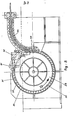
- FIG. 5 represents a casting wheel (29) driven by a motor, not shown, which rotates in the direction of the arrow and the rim (30) of which is fitted with movable flaps such as (31).
- the flaps (31) are supported on the edges of the rim in an angular zone situated between the point of introduction of the liquid metal into the groove by a supply means (32) to a point close to that where the solidified bar or strip (33) is extracted from the groove by a suitable means such as guide rollers (34).
- the flaps are in the open position and arranged so as not to interfere with the operation of the means of extraction, and not to obstruct the passage of the solidified bar or strip which is generally directed towards reduction means for example by rolling, and not to obstruct the operation of the liquid metal supply means either .
- an essential feature of the invention is that the movable flaps (31) permanently accompany the casting wheel in its rotation and that each of them maintains along the rim thereof, a determined location.
- Connecting hooks (35), shown schematically in Figure 5, maintain the flaps against each other, to prevent any leakage of liquid metal through a possible space between two adjacent flaps.
- a fixed ramp (36) surrounds the casting wheel throughout the angular region where the flaps must remain closed, and ensures the plating thereof on the rim flange by means of conventional clamping means.
- FIG. 6 shows in detail an advantageous embodiment of the flaps according to the invention.
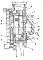
- the casting wheel (29) which is shown in partial section along a plane parallel to the axis, comprises a rim (30) provided with a groove (37) intended to receive the liquid metal and to allow it to solidify.
- This rim is cooled by a circulation of water which takes place in a known manner in the annular space (38) and which is maintained by a system of arrival and departure of water, which takes place for example through the axis of the wheel which is hollow and comprises, in known manner, the necessary connections with the external network.
- the flap (39) is an assembly which is articulated by means of an arm (40) on the axis (41) which is itself fixed in a yoke rigidly connected to the structure of the wheel - casting near the rim.
- the arm (40) is extended beyond the axis (41) by a lever (42) on which is fixed a roller (43).
- each flap In practice, the opening and closing of each flap are caused for an angular position very well determined relative to the frame, as seen in Figure 7, by means of fixed ramps (44) integral with the frame on which is mounted the casting wheel.
- the profile of these ramps is designed to move the rollers (43) up or down according to the desired angle.
- the closing plate (45) of the shutter shown in section is centered relative to the rim (30) by means of centering pins, such as (46).
- These pins connected to the closure plate (45) penetrate at the time of the tilting of the flap, when it comes to bear on the rim (30), in housings such as (47) formed in this rim.
- the closure plate (45) is placed in a reproducible manner each time it comes to bear on the rim (30).
- an elastic tightening means is used.
- each flap comprises a housing (48) inside which the closure plate is fixed elastically by springs such as (49).
- the housing has rollers such as (50).
- the flaps engage in a space delimited by a fixed annular ramp (36) concentric with the wheel against which the rollers (50) come rou -1st.
- the distance between the ramp and the rim of the casting wheel is calculated so that the springs (49) are compressed by means of the rollers (50).
- the closure plate is thus applied against the rim with sufficient force.
- each closure plate is equipped with an internal cooling means (51).
- an internal cooling means 51).
- water is most often used as a cooling fluid, it can be seen that the use of flaps articulated directly on the casting wheel allows an extremely easy supply of fluid from the wheel itself which, in turn, is supplied without difficulty thanks to fluid inlets and outlets at its axis.
- the closure plate (45) has a double wall inside which water passages (51) are provided.
- Water inlet and outlet fittings (52) and (53) Figures 6, 7, 8 and 9, are connected by flexible connecting tubes, for example made of elastomer, symbolized in (54), to inlets and corresponding water outlets such as (55-56), formed on the lateral face of the casting wheel not far from the point of attachment of the tilting axis (41).
- the length of these connecting tubes is determined so as not to prevent tilting of the flap.
- a system for attaching successive flaps to each other is shown in the figure. 9. It can be seen that each flap has a hook (57) articulated around an axis (58) which is capable of being hooked to a stud (59).
- the opening and closing of the hook is controlled by a roller (60) which is raised or lowered by suitably arranged stops.
- the connecting means thus produced makes it possible to avoid leakage of liquid metal between the closure plates.
- shutters of relatively small dimensions, and of compact structure, articulated separately on the casting wheel itself, makes it possible to use, for the closure plate, the metals most suitable for supporting direct contact with the metal to be poured.
- metals with high specific heat and / or high thermal conductivity such as aluminum, magnesium, copper, silver or else certain alloys of these metals.
- metals with high specific heat and / or high thermal conductivity such as aluminum, magnesium, copper, silver or else certain alloys of these metals.
- it is preferable to make the closure plate in the same metal as the rim that is to say in many cases, in copper or in alloys with a high copper content. In many cases, only the face of the closure plate, which is in contact with the liquid metal, will be made of high conductivity metal.
- the second wall, or outer wall of the plate can be made of a metal of much higher mechanical strength. Thanks to vigorous fluid cooling of the closure plate, practically no deformation is observed due to phenomena of differential expansion.
- the dimensions of the closing plates are calculated so as to take account of the expansion of the rim during use in order to avoid leakage of liquid metal.
- the embodiment provided for closing the casting wheel makes it possible to envisage a very significant modification of the profile of the bars or strips cast by this process.
- the angle formed between the inner face of the metal strip and the side walls of the groove is approximately 80 ° . This results from the need for a draft of about ten degrees to be able to get the bar out of the throat. In addition, there can be no rounding at the top of this angle which is therefore sharp.
- connection between the closure plate and the rim is thus produced on the lateral faces of the bar and, thanks to the centering devices which are used, no relative transverse displacement of this closure plate is observed with respect to the rim .
- the invention relates not only to the casting device which has just been described, but also to a method of casting on a wheel of metals or alloys with a high melting point such as copper and its alloys, steels and other metals. or high melting point alloys.
- This method allows, by closing the rim in the casting area, by means of flaps cooled by the circulation of such a fluid. as water, to obtain a very rapid solidification of the cast metals or alloys.
- the means for supplying liquid metal may be placed in a controlled atmosphere.
Landscapes
- Engineering & Computer Science (AREA)
- Mechanical Engineering (AREA)
- Continuous Casting (AREA)
- Developing Agents For Electrophotography (AREA)
- Packging For Living Organisms, Food Or Medicinal Products That Are Sensitive To Environmental Conditiond (AREA)
- Containers Having Bodies Formed In One Piece (AREA)
- Braking Arrangements (AREA)
- Wire Processing (AREA)
- Superconductors And Manufacturing Methods Therefor (AREA)
- Metal Extraction Processes (AREA)
- Lift-Guide Devices, And Elevator Ropes And Cables (AREA)
Abstract
Description
Le procédé et le dispositif, qui font l'objet de l'invention, concernent de la façon la plus générale la coulée continue des métaux sur roue.The method and the device, which are the subject of the invention, relate most generally to the continuous casting of metals on wheels.
Ce procédé et ce dispositif permettent la coulée continue de métaux ou alliages sous forme de barres ou de bandes. Ce procédé s'applique à une très large gamme de métaux ou alliages. Bien qu'il puisse être utilisé efficacement pour la coulée de métaux à relativement bas point de fusion tels que l'aluminium, il convient particulièrement bien pour la coulée des métaux à point de fusion élevé tels que le cuivre et ses alliages et, surtout, l'ensemble des alliages ferreux, aciers ordinaires, alliés, inoxydables, réfractaires. Il convient aussi à la coulée d'autres métaux ou alliages réfractaires tels que les superalliages.This method and this device allow the continuous casting of metals or alloys in the form of bars or strips. This process applies to a very wide range of metals or alloys. Although it can be used effectively for the casting of relatively low melting point metals such as aluminum, it is particularly suitable for the casting of high melting point metals such as copper and its alloys and, above all, all ferrous alloys, ordinary steels, alloys, stainless steels, refractory materials. It is also suitable for casting other metals or refractory alloys such as superalloys.
La description et les figures ci-après permettent de mieux comprendre les caractéristiques du procédé qui fait l'objet de l'invention.
- Figure 1 : dispositif connu de coulée continue sur roue avec fermeture de la jante par un ruban métallique sans fin.
- Figure 2 : détail de la roue de la figure 1.
- Figure 5 : ensemble comprenant le dispositif de la figure 1 et une installation de laminage continu qui lui est associée de façon connue. Figure 4 : dispositif de coulée continue sur roue, également connu, dans lequel le ruban métallique s'enroule sur des poulies de renvoi.
- Figure 5 : dispositif de coulée continue sur roue avec fermeture de la jante par des volets suivant l'invention.
- Figure 6 : vue de la jante de la roue de coulée et d'un volet, suivant l'invention, en position de fermeture.
- Figure 7 : vue d'un volet, suivant l'invention, en position d'ouverture.
- Figure 8 : détail d'un volet, suivant l'invention, en appui sur la jante de la roue de coulée.
- Figure 9 : vue du mode d'accrochage suivant l'invention, des volets les uns aux autres.
- Figure 1: known device for continuous casting on a wheel with closure of the rim by an endless metal strip.
- Figure 2: detail of the wheel in Figure 1.
- Figure 5: assembly comprising the device of Figure 1 and a continuous rolling installation associated with it in known manner. Figure 4: continuous casting device on a wheel, also known, in which the metal strip is wound on idler pulleys.
- Figure 5: continuous casting device on wheel with closure of the rim by flaps according to the invention.
- Figure 6: view of the rim of the casting wheel and a flap, according to the invention, in the closed position.
- Figure 7: view of a flap, according to the invention, in the open position.
- Figure 8: detail of a flap, according to the invention, pressing on the rim of the casting wheel.
- Figure 9: view of the method of attachment according to the invention, the flaps to each other.
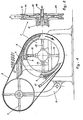
Le brevet FR. 981 897 décrit un procédé de coulée continue sur roue., Les figures 1 et 2 permettent de comprendre les caractéristiques de ce procéda maintenant bien connu. Une roue (1), entraînée en rotation à vitesse lente par un moteur non représenté, comporte une jante creuse (2) dans la gorge (3) de laquelle un dispositif d'alimentation (4) permet d'introduire en (5) le métal liquide au moyen d'une busette.The FR patent. 981 897 describes a continuous casting process on a wheel., FIGS. 1 and 2 make it possible to understand the characteristics of this now well known procedure. A wheel (1), driven in rotation at slow speed by a motor not shown, has a hollow rim (2) in the groove (3) from which a supply device (4) allows to introduce in (5) the liquid metal by means of a nozzle.
Un ruban métallique sans fin (6) s'enroule sur la roue de coulée et sur une roue libre (7) disposée dans le même plan. Cette roue libre est montée sur un bras oscillant (8) qui joue le rôle de tendeur. Le ruban est ainsi plaqué sur les bords (9) de la jante de la roue (1) et empêche donc le métal coulé en (5) de sortir de la gorge. La jante est refroidie par circulation d'eau dans l'espace (10), ce qui permet une solidification rapide du métal dans la gorge. Cette eau est introduite par l'axe de la roue en (11) puis envoyée dans l'espace (10) à travers deux rayons diamétralement opposés (12) et (13). Le retour: de l'eau s'effectue par deux autres rayons (14) et (15) et à travers l'axe de la roue en (16). La roue tourne dans le sens de la flèche et le serrage du ruban métallique sur la jante est tel qu'il ne se produit pas de glissement notable. La vitesse de solidification du métal dans la gorge est relativement rapide et la barre solidifiée (17) est extraite en continu de la gorge à l'endroit où le ruban métallique se décolle de la jante pour aller s'enrouler sur la roue (7). On voit que la barre (17) formée ainsi de façon continue doit être déviée par rapport au plan de symétrie de la jante (2) d'une quantité suffisante pour permettre de la faire sortir de l'espace délimité par les roues (1) et (7) et le ruban (6) sans heurter ce dernier. Une telle déviation ne présente pas de difficultés particulières dans le cas de barres de faible section en un métal de dureté limitée. Elle est, par contre, plus difficilement réalisable lorsqu'il s'agit de barres de forte section ou de bandes relativement larges, ou encore, de métaux ou alliages durs.An endless metal ribbon (6) is wound on the casting wheel and on a free wheel (7) arranged in the same plane. This freewheel is mounted on an oscillating arm (8) which acts as a tensioner. The ribbon is thus pressed against the edges (9) of the rim of the wheel (1) and therefore prevents the metal cast in (5) from coming out of the groove. The rim is cooled by circulation of water in the space (10), which allows rapid solidification of the metal in the groove. This water is introduced by the axis of the wheel at (11) then sent into the space (10) through two diametrically opposite spokes (12) and (13). The return: water is carried out by two other spokes (14) and (15) and through the axis of the wheel at (16). The wheel turns in the direction of the arrow and the tightening of the metal strip on the rim is such that no noticeable slip occurs. The speed of solidification of the metal in the groove is relatively rapid and the solidified bar (17) is continuously extracted from the groove at the place where the metal strip peels off the rim to go and wind on the wheel (7) . It can be seen that the bar (17) thus formed continuously must be deflected with respect to the plane of symmetry of the rim (2) by an amount sufficient to allow it to come out of the space delimited by the wheels (1) and (7) and the ribbon (6) without hitting the latter. Such a deviation does not present any particular difficulties in the case of bars of small section made of a metal of limited hardness. On the other hand, it is more difficult to produce in the case of bars of large section or relatively wide strips, or even of hard metals or alloys.
La figure 3 représente, toujours d'après l'enseignement du même brevet cité ci-dessus, la barre (17) extraite de la roue de coulée (1) qui est ainsi déviée de son plan de sortie puis envoyée vers une installation de laminage continu (18).FIG. 3 represents, still according to the teaching of the same patent cited above, the bar (17) extracted from the casting wheel (1) which is thus deflected from its outlet plane and then sent to a rolling installation continuous (18).
Afin de remédier à l'inconvénient de cette déviation de la barre, le FR. 1 178 580 propose de faire circuler le ruban ou bande, qui assure l'obturation de la jante, non pas sur une seule roue libre, jouant le rôle de tendeur, mais sur, au moins, deux. roues libres.In order to remedy the drawback of this deviation from the bar, the FR. 1,178,580 proposes to circulate the tape or strip, which ensures the sealing of the rim, not on a single free wheel, playing the role of tensioner, but on, at least, two. freewheels.
On voit, à la figure 4, une disposition proposée dans ce brevet, dans laquelle le ruban métallique sans fin (19), qui assure la fermeture de la jante creuse (20) de la roue de coulée (21), s'enroule sur deux poulies de renvoi (22) et (23) et une poulie de tension (24). Par ailleurs, des rouleaux d'appui (25) et (26) permettent d'améliorer le contact entre le ruban métallique et les bords de la jante. De plus, pour améliorer le refroidissement du ruban métallique, un support mobile (27) est pourvu de moyens d'arrosage (28) qui projettent l'eau sur la face apparente du ruban.We see, in Figure 4, an arrangement proposed in this patent, in which the endless metal strip (19), which ensures the closure of the hollow rim (20) of the casting wheel (21), is wound on two return pulleys (22) and (23) and a tension pulley (24). Furthermore, support rollers (25) and (26) make it possible to improve the contact between the metal strip and the edges of the rim. In addition, to improve the cooling of the metal strip, a movable support (27) is provided with sprinkling means (28) which project water onto the visible face of the strip.
De nombreuses modifications au procédé de coulée continue sur roue, qui vient d'être décrit, ont été proposées. Cependant, l'expérience a montré que, si ce procédé s'adapte bien à la coulée continue de métaux à relativement bas point de fusion, tels que l'aluminium, il est beaucoup plus difficile à mettre en oeuvre dans le cas où on désire effectuer la coulée de métaux à point de fusion beaucoup plus élevé tels que le cuivre ou encore tels que l'acier. Il devient alors de plus en plus difficile d'assurer un refroidissement satisfaisant du ruban métallique qui assure la fermeture de la jante. Pour des raisons de caractéristiques mécaniques, ce ruban est généralement réalisé en acier, et si son refroidissement est insuffisant, il risque, d'une part, d'être attaqué par le métal liquide qui vient à son contact et, d'autre part, de perdre par recuit une partie de ses caractéristiques de résistance mécanique. Par ailleurs, les efforts de torsion alternée auxquels ce ruban est soumis sont une cause de fissuration transversale, au bout d'un temps qui peut être court et, enfin, l'arrosage du ruban sur sa face externe; pratiquement nécessaire dans tous les cas, n'est pas dépourvu de risque. Il peut arriver, en effet, que l'eau ainsi projetée vienne en contact avec le métal liquide qui est coulé dans la jante. On risque alors de voir se produire des explosions qui provoquent, dans la plupart des cas, la rupture du ruban métallique et peuvent aussi endomna- ger très sérieusement la roue de coulée.Many modifications to the process of continuous casting on a wheel, which has just been described, have been proposed. However, experience has shown that, if this process adapts well to the continuous casting of metals with relatively low melting point, such as aluminum, it is much more difficult to implement in the case where it is desired casting much higher melting point metals such as copper or even steel. It then becomes increasingly difficult to ensure satisfactory cooling of the metal strip which ensures the closure of the rim. For reasons of mechanical characteristics, this strip is generally made of steel, and if its cooling is insufficient, it risks, on the one hand, being attacked by the liquid metal which comes into contact with it and, on the other hand, to lose by annealing part of its mechanical strength characteristics. Furthermore, the alternating torsional forces to which this ribbon is subjected are a cause of transverse cracking, after a time which may be short and, finally, the watering of the ribbon on its external face; practically necessary in all cases, is not without risk. It may happen, in fact, that the water thus projected comes into contact with the liquid metal which is poured into the rim. There is then a risk of explosions occurring which in most cases cause the metal strip to break and can also seriously damage the casting wheel.
Enfin, un sérieux défaut des produits obtenus par coulée de barres sur jante de roue, avec obturation par ruban métallique, est l'existence de deux angles vifs sur le produit solidifié à l'endroit où les deux bords du ruban se raccordent aux parois latérales de la jante. Ces angles vifs sont une cause de défauts et, très souvent, il est nécessaire de faire subir à la barre qui est extraite de la jante, un ébarbage avant de la faire passer dans le laminoir.Finally, a serious defect in the products obtained by casting bars on a wheel rim, with sealing by metal tape, is the existence of two sharp angles on the solidified product at the place where the two edges of the tape are connected to the side walls. from the rim. These sharp angles are a cause of defects and, very often, it is necessary to subject the bar, which is extracted from the rim, to deburring before passing it through the rolling mill.
On a alors recherché la possibilité d'étendre les applications de la coulée sur roue à toutes sortes de métaux ou alliages et, en particulier, à ceux à haut point de fusion, en s'affranchissant des limitations actuellement imposées à l'utilisation de cette méthode de coulée, en particulier par les moyens d'obturation de la jante dont on dispose.We then looked for the possibility of extending the applications of wheel casting to all kinds of metals or alloys and, in particular, to those with high melting point, overcoming the limitations currently imposed on the use of this casting method, in particular by means of sealing off the rim available.
Le dispositif et le procédé suivant l'invention permettent précisément de s'affranchir de ces limitations.The device and the method according to the invention precisely allow these limitations to be overcome.
Le dispositif suivant l'invention est constitué par une roue de coulée comportant une jante à gorge dont l'obturation est assurée par des volets mobiles qui accompagnent de façon permanente la roue dans sa rotation. L'ouverture et la fermeture de ces volets sont commandées par des moyens de commande qui permettent la fermeture des volets dans la zone d'introduction du métal liquide et leur ouverture dans la zone d'extraction de la barre ou de la bande solidifiée. De façon préférentielle, les volets comportent un moyen de refroidissement par circulation interne d'eau et de plus, des moyens de serrage assurent le plaquage des volets sur la jante de la roue avec une pression suffisante. Enfin, des moyens de liaison permettent de solidariser les-volets les uns avec les autres.The device according to the invention consists of a casting wheel comprising a grooved rim, the closure of which is ensured by movable flaps which permanently accompany the wheel in its rotation. The opening and closing of these shutters are controlled by control means which allow the shutters to be closed in the zone of introduction of the liquid metal and their opening in the zone for extracting the bar or the solidified strip. Preferably, the flaps comprise a means of cooling by internal circulation of water and, moreover, clamping means ensure that the flaps are pressed against the rim of the wheel with sufficient pressure. Finally, connecting means make it possible to secure the shutters with each other.
De façon beaucoup plus détaillée, on va décrire maintenant un mode de réalisation du dispositif suivant l'invention.In much more detail, an embodiment of the device according to the invention will now be described.
La figure 5 représente une roue de coulée (29) entraînée par un moteur non représenté, qui tourne dans le sens de la flèche et dont la jante (30) est équipée de volets mobiles tels que (31). Comme le montre cette figure, les volets (31) sont en appui sur les bords de la jante dans une zone angulaire située entre le point d'introduction du métal liquide dans la gorge par un moyen d'alimentation (32) jusqu'à un point proche de celui où la barre ou la bande solidifiée (33) est extraite de la gorge par un moyen convenable tel que les rouleaux de guidage (34). Dans toute la zone qui s'étend entre le point d'extraction de la barre solidifiée et le point d'introduction du métal liquide, les volets sont en position d'ouverture et disposés de façon à ne pas gêner le fonctionnement du moyen d'extraction, et à ne pas faire obstacle au passage de la barre ou de la bande solidifiée qui est généralement dirigée vers des moyens de réduction par exemple par laminage, et à ne pas faire obstacle non plus au fonctionnement du moyen d'alimentation en métal liquide.FIG. 5 represents a casting wheel (29) driven by a motor, not shown, which rotates in the direction of the arrow and the rim (30) of which is fitted with movable flaps such as (31). As this figure shows, the flaps (31) are supported on the edges of the rim in an angular zone situated between the point of introduction of the liquid metal into the groove by a supply means (32) to a point close to that where the solidified bar or strip (33) is extracted from the groove by a suitable means such as guide rollers (34). Throughout the area which extends between the point of extraction of the solidified bar and the point of introduction of the liquid metal, the flaps are in the open position and arranged so as not to interfere with the operation of the means of extraction, and not to obstruct the passage of the solidified bar or strip which is generally directed towards reduction means for example by rolling, and not to obstruct the operation of the liquid metal supply means either .
Une particularité essentielle de l'invention est que les volets mobiles (31) accompagnent de façon permanente la roue de coulée dans sa rotation et que chacun d'eux conserve le long de la jante de celle-ci, un emplacement déterminé. Des crochets de liaison (35),:représentés de façon schématique sur la figure 5, assurent le maintien des volets les uns contre les autres, pour éviter toute fuite de métal liquide à travers un éventuel espace entre deux volets adjacents. Par ailleurs, comme on le verra plus loin de façon détaillée, une rampe fixe (36) entoure la roue de coulée dans toute la région angulaire où les volets doivent rester fermés, et assure le plaquage de ceux-ci sur le rebord de la jante par l'intermédiaire d'un moyen de serrage classique. On voit sur la figure 6, de façon détaillée, un mode avantageux de réalisation des volets suivant l'invention.An essential feature of the invention is that the movable flaps (31) permanently accompany the casting wheel in its rotation and that each of them maintains along the rim thereof, a determined location. Connecting hooks (35), shown schematically in Figure 5, maintain the flaps against each other, to prevent any leakage of liquid metal through a possible space between two adjacent flaps. Furthermore, as will be seen in detail below, a fixed ramp (36) surrounds the casting wheel throughout the angular region where the flaps must remain closed, and ensures the plating thereof on the rim flange by means of conventional clamping means. FIG. 6 shows in detail an advantageous embodiment of the flaps according to the invention.
La roue de coulée (29), qui est représentée en coupe partielle suivant un plan parallèle à l'axe, comporte une jante (30) pourvue d'une gorge (37) destinée à recevoir le métal liquide et à permettre sa solidification. Cette jante est refroidie par une circulation d'eau qui a lieu de façon connue dans l'espace annulaire (38) et qui est entretenue par un système d'arrivée-et de départ d'eau, qui s'effectue par exemple à travers l'axe de la roue qui est creux et comporte de façon connue, les liaisons nécessaires avec le réseau extérieur. Le volet (39) est un ensemble qui s'articule au moyen d'un bras (40) sur l'axe (41) qui est lui-même fixé dans une chape liée rigidement à la structure de la roue - de coulée au voisinage de la jante. Le bras (40) est prolongé au-delà de l'axe (41) par un levier (42) sur lequel est fixé un galet (43).The casting wheel (29), which is shown in partial section along a plane parallel to the axis, comprises a rim (30) provided with a groove (37) intended to receive the liquid metal and to allow it to solidify. This rim is cooled by a circulation of water which takes place in a known manner in the annular space (38) and which is maintained by a system of arrival and departure of water, which takes place for example through the axis of the wheel which is hollow and comprises, in known manner, the necessary connections with the external network. The flap (39) is an assembly which is articulated by means of an arm (40) on the axis (41) which is itself fixed in a yoke rigidly connected to the structure of the wheel - casting near the rim. The arm (40) is extended beyond the axis (41) by a lever (42) on which is fixed a roller (43).
On comprend qu'en appliquant sur le galet des forces dirigées soit vers le haut (flèche A), soit vers le bas (flèche B), on agit sur le levier (41) qui, soit maintient le volet (38) en appui sur les bords de la jante (30) par sa plaque de fermeture (45), soit, au contraire, le soulève.We understand that by applying forces on the roller either upwards (arrow A) or downwards (arrow B), we act on the lever (41) which either keeps the flap (38) in contact with the edges of the rim (30) by its closure plate (45), or, on the contrary, raises it.
On voit, figure 7, le volet (39) en position ouverte, l'espace au-dessus de la gorge de la jante est alors complétement dégagé, ce qui permet d'engager dans cette gorge, dans des zones déterminées, des moyens d'extraction de la barre solidifiée ou un moyen d' introduction du métal ou alliage liquide.We see, Figure 7, the flap (39) in the open position, the space above the groove of the rim is then completely cleared, which allows to engage in this groove, in specific areas, means d extraction of the solidified bar or a means of introducing the metal or liquid alloy.
Dans la pratique, l'ouverture et la fermeture de chaque volet sont provoquées pour une position angulaire très bien déterminée par rapport au bâti, comme on le voit figure 7, au moyen de rampes fixes (44) solidaires du bâti sur lequel est montée la roue de coulée. Le profil de ces rampes est conçu pour déplacer les galets (43) vers le haut ou vers le bas suivant l'angle voulu.In practice, the opening and closing of each flap are caused for an angular position very well determined relative to the frame, as seen in Figure 7, by means of fixed ramps (44) integral with the frame on which is mounted the casting wheel. The profile of these ramps is designed to move the rollers (43) up or down according to the desired angle.
On conçoit qu'il est absolument nécessaire d'obtenir une fermeture étanche de la gorge pour éviter toute fuite de métal liquide qui serait une cause de perte de métal et, surtout, de défaut de surface. Pour celà, il est possible, de façon complémentaire, d'améliorer le centrage des volets par rapport aux jantes et aussi d'assurer, d'une part, un serrage avec une pression suffisante du volet sur la jante et, d'autre part, un maintien des volets successifs les uns contre les autres grâce à un moyen de liaison tel que des crochets.It is understood that it is absolutely necessary to obtain a tight closure of the throat to avoid any leakage of liquid metal which would be a cause of loss of metal and, above all, of surface defect. For this, it is possible, in a complementary manner, to improve the centering of the flaps relative to the rims and also to ensure, on the one hand, a tightening with sufficient pressure of the flap on the rim and, on the other hand , maintaining the successive flaps against each other by means of a connecting means such as hooks.
On voit sur la figure 8 que la plaque de fermeture (45) du volet figurée en coupe, est centrée par rapport à la jante (30) au moyen de goupilles de centrage, telles que (46). Ces goupilles reliées à la plaque de fermeture (45) pénètrent au moment du basculement du volet, lorsqu'il vient en appui sur la jante (30), dans des logements tels que (47) ménagés dans cette jante. De cette façon, la plaque de fermeture (45) est mise en place de façon reproductible chaque fois qu'elle vient en appui sur la jante (30). Par ailleurs, afin d'assurer un serrage constant de cette plaque de fermeture sur la jante, un moyen de serrage élastique est utilisé.It can be seen in FIG. 8 that the closing plate (45) of the shutter shown in section is centered relative to the rim (30) by means of centering pins, such as (46). These pins connected to the closure plate (45) penetrate at the time of the tilting of the flap, when it comes to bear on the rim (30), in housings such as (47) formed in this rim. In this way, the closure plate (45) is placed in a reproducible manner each time it comes to bear on the rim (30). Furthermore, in order to ensure constant tightening of this closure plate on the rim, an elastic tightening means is used.
Corme le montre la figure, chaque volet comporte un boîtier (48) à l'intérieur duquel la plaque de fermeture est fixée élastiquement par des ressorts tels que (49). A la partie supérieure, le boîtier comporte des rouleaux tels que (50). Après fermeture de chaque volet, au voisinage du point de remplissage de la gorge par le métal liquide, les volets s'engagent dans un espace délimité par une rampe fixe annulaire (36) concentrique à la roue contre laquelle les rouleaux (50) viennent rou-1er. La distance entre la rampe et la jante de la roue de coulée est calculée de façon que les ressorts (49) soient comprimés par l'intermédiaire des rouleaux (50). La plaque de fermeture est ainsi appliquée contre la jante avec une force suffisante. Ce mode de réalisation permet d'absorber les dilatations et des surépaisseurs éventuelles provoquées par des débordements de métal liquide.As shown in the figure, each flap comprises a housing (48) inside which the closure plate is fixed elastically by springs such as (49). At the top, the housing has rollers such as (50). After closing each flap, in the vicinity of the filling point of the groove with liquid metal, the flaps engage in a space delimited by a fixed annular ramp (36) concentric with the wheel against which the rollers (50) come rou -1st. The distance between the ramp and the rim of the casting wheel is calculated so that the springs (49) are compressed by means of the rollers (50). The closure plate is thus applied against the rim with sufficient force. This embodiment makes it possible to absorb the expansions and possible extra thicknesses caused by liquid metal overflows.
Corme le montre également la figure 8, chaque plaque de fermeture est équipée d'un moyen de refroidissement interne (51). Comme on fait appel le plus souvent à l'eau comme fluide de refroidissement, on voit que l'utilisation de volets articulés directement sur la roue de coulée permet une alimentation en fluide extrêmement facile à partir de la roue elle-même qui, elle, est alimentée sans difficulté grâce à des entrées et sorties de fluide au niveau de son axe.Corme also shows it in FIG. 8, each closure plate is equipped with an internal cooling means (51). As water is most often used as a cooling fluid, it can be seen that the use of flaps articulated directly on the casting wheel allows an extremely easy supply of fluid from the wheel itself which, in turn, is supplied without difficulty thanks to fluid inlets and outlets at its axis.
Comme le montrent les figures 6 et 8, la plaque de fermeture (45) comporte une double paroi à l'intérieur de laquelle des passages d'eau (51) sont ménagés. Des raccords d'entrée et de sortie d'eau (52) et (53) figures 6, 7, 8 et 9, sont reliés par des tubes de liaison flexibles, par exemple en élastomère, symbolisés en (54), à des entrées et sorties d'eau correspondantes telles que (55-56), ménagées sur la face latérale de la roue de coulée non loin du point de fixation de l'axe de basculement (41). La longueur de ces tubes de liaison est déterminée de façon à ne pas faire obstacle au basculement du volet. Enfin, un système d'accrochage des volets successifs les uns aux autres est représenté figure 9. On voit que chaque volet comporte un crochet (57) articulé autour d'un axe (58) qui est susceptible de s'accrocher à un tenon (59). L'ouverture et la fermeture du crochet sont commandées par un galet (60) qui est soulevé ou abaissé par des butées convenablement disposées. Le moyen de liaison ainsi réalisé permet d'éviter les fuites de métal liquide entre les plaques de fermeture.As shown in Figures 6 and 8, the closure plate (45) has a double wall inside which water passages (51) are provided. Water inlet and outlet fittings (52) and (53) Figures 6, 7, 8 and 9, are connected by flexible connecting tubes, for example made of elastomer, symbolized in (54), to inlets and corresponding water outlets such as (55-56), formed on the lateral face of the casting wheel not far from the point of attachment of the tilting axis (41). The length of these connecting tubes is determined so as not to prevent tilting of the flap. Finally, a system for attaching successive flaps to each other is shown in the figure. 9. It can be seen that each flap has a hook (57) articulated around an axis (58) which is capable of being hooked to a stud (59). The opening and closing of the hook is controlled by a roller (60) which is raised or lowered by suitably arranged stops. The connecting means thus produced makes it possible to avoid leakage of liquid metal between the closure plates.
L'utilisation des volets, de.relativement petites dimensions, et de structure compacte, articulés séparément sur la roue de coulée elle-même, permet d'utiliser, pour la plaque de fermeture, les métaux les plus appropriés à supporter un contact direct avec le métal qu'il s'agit de couler. C'est ainsi qu'il sera possible d'utiliser, pour réaliser la plaque de femeture, des métaux à grande chaleur spécifique et/ou grande conductivité thermique, tels que l'aluminium, le magnésium, le cuivre, l'argent ou encore certains alliages de ces métaux. Le plus souvent,'on préférera réaliser la plaque de fermeture dans le même métal que la jante, c'est-à-dire dans bien des cas, en cuivre ou en alliages à haute teneur en cuivre. Dans bien des cas, seule la face de la plaque de fermeture, qui est en contact avec le métal liquide, sera réalisée en métal à haute conductivité. La deuxième paroi, ou paroi extérieure de la plaque, pourra être réalisée en un métal de résistance mécanique beaucoup plus élevée. Grâce à un refroidissement énergique par fluide de la plaque de fermeture, on n'observe pratiquement pas de déformation dûe à des phénomènes de dilatation différentielle. Les dimensions des plaques de fermeture sont calculées de façon à tenir compte de la dilatation de la jante en cours d'utilisation afin d'éviter les fuites de métal liquide.The use of shutters, of relatively small dimensions, and of compact structure, articulated separately on the casting wheel itself, makes it possible to use, for the closure plate, the metals most suitable for supporting direct contact with the metal to be poured. Thus, it will be possible to use, for producing the closure plate, metals with high specific heat and / or high thermal conductivity, such as aluminum, magnesium, copper, silver or else certain alloys of these metals. Most often, it is preferable to make the closure plate in the same metal as the rim, that is to say in many cases, in copper or in alloys with a high copper content. In many cases, only the face of the closure plate, which is in contact with the liquid metal, will be made of high conductivity metal. The second wall, or outer wall of the plate, can be made of a metal of much higher mechanical strength. Thanks to vigorous fluid cooling of the closure plate, practically no deformation is observed due to phenomena of differential expansion. The dimensions of the closing plates are calculated so as to take account of the expansion of the rim during use in order to avoid leakage of liquid metal.
Le mode de réalisation prévu pour la fermeture de la roue de coulée permet d'envisager une très importante modification du profil des barres ou des bandes coulées par ce procédé. En effet, dans la coulée sur roue classique avec femeture de la gorge par un ruban métallique, l'angle formé entre la face intérieure du ruban métallique et les parois latérales de la gorge est d'environ 800. Ceci résulte de la nécessité d'une dépouille d'environ une dizaine de degrés pour pouvoir sortir la barre de la gorge. De plus, il ne peut y avoir d'arrondi au sommet de cet angle qui est donc vif. Par ailleurs, au fur et à mesure de l'usure des parois de la gorge, il risque de se produire de petites infiltrations de métal liquide entre le ruban et le bord de la jante qui sont une raison supplémentaire pour effectuer un ébarbage.The embodiment provided for closing the casting wheel makes it possible to envisage a very significant modification of the profile of the bars or strips cast by this process. In fact, in conventional wheel casting with closing of the groove by a metal strip, the angle formed between the inner face of the metal strip and the side walls of the groove is approximately 80 ° . This results from the need for a draft of about ten degrees to be able to get the bar out of the throat. In addition, there can be no rounding at the top of this angle which is therefore sharp. In addition, as and when wear of the throat walls, there is a risk of small liquid metal infiltrations between the strip and the edge of the rim, which is another reason for deburring.
Dans le cas, au contraire, de la présente invention, grâce à la rigidité des plaques de fermeture qui sont pratiquement indéformables, on peut donner à la face de ces plaques, qui est en regard de la jante, un profil complémentaire de celui de la gorge.In the case, on the contrary, of the present invention, thanks to the rigidity of the closure plates which are practically non-deformable, it is possible to give the face of these plates, which is opposite the rim, a profile complementary to that of the throat.
Sur la figure 8, on voit une telle plaque de fermeture (45) qui présente des arrondis (61) et (62) grâce auxquels la barre qui sera coulée dans la jante, comportera seulement des arêtes arrondies et pourra donc être laminée dans des conditions particulièrement favorables.In Figure 8, we see such a closure plate (45) which has rounded (61) and (62) by which the bar which will be cast in the rim, will only have rounded edges and can therefore be laminated under conditions particularly favorable.
Le raccordement entre la plaque de fermeture et la jante est ainsi réalisé sur les faces latérales de la barre et, grâce aux dispositifs de centrage qui sont utilisés, on n'observe pas de déplacement transversal relatif de cette plaque de fermeture par rapport à la jante.The connection between the closure plate and the rim is thus produced on the lateral faces of the bar and, thanks to the centering devices which are used, no relative transverse displacement of this closure plate is observed with respect to the rim .
L'invention concerne, non seulement, le dispositif de coulée qui vient d'être décrit, mais aussi un procédé de coulée sur roue de métaux où alliages à haut point de fusion tels que le cuivre et ses alliages, les aciers et les autres métaux ou alliages à haut point de fusion.The invention relates not only to the casting device which has just been described, but also to a method of casting on a wheel of metals or alloys with a high melting point such as copper and its alloys, steels and other metals. or high melting point alloys.
Ce procédé permet, grâce à la fermeture de la jante dans la zone de coulée, au moyen de volets refroidis par circulation d'un fluide tel. que l'eau, d'obtenir une solidification très rapide des métaux ou alliages coulés.This method allows, by closing the rim in the casting area, by means of flaps cooled by the circulation of such a fluid. as water, to obtain a very rapid solidification of the cast metals or alloys.
Ceci réduit ainsi les risques de ségrégation et permet d'obtenir des structures de métal brut de coulée à grain particulièrement fin.'Ce procédé permet également d'obtenir des barres coulées dont la section ne présente pas d'angles vifs, ce qui évite les risques de replis, et peut même se rapprocher du rond.This therefore reduces the risk of segregation and makes it possible to obtain particularly fine-grained cast metal structures. This process also makes it possible to obtain cast bars whose section does not have sharp angles, which avoids the risk of folds, and can even approach the round.
Différents moyens d'alimentation en métal liquide de la roue de coulée peuvent être envisagés suivant les cas. On peut utiliser, en particulier, des busettes ou encore des canaux à niveau sensiblement constant.Different means for supplying liquid metal to the casting wheel can be envisaged depending on the case. We can use, in particular link, nozzles or channels at substantially constant level.
Dans le cas de la coulée de.- métaux oxydables tels que le cuivre, on pourra mettre en atmosphère contrôla le moyen d'alimentation en métal liquide.In the case of the pouring of oxidizable metals such as copper, the means for supplying liquid metal may be placed in a controlled atmosphere.
De très nombreuses variantes du dispositif suivant l'invention peuvent être réalisées, qui font partie de l'invention.Many variants of the device according to the invention can be produced, which form part of the invention.
Claims (8)
Priority Applications (1)
| Application Number | Priority Date | Filing Date | Title |
|---|---|---|---|
| AT82420062T ATE16900T1 (en) | 1981-05-15 | 1982-05-12 | METHOD AND APPARATUS FOR CONTINUOUS CASTING USING A CASTING WHEEL WITH PERIPHERAL GROOVE. |
Applications Claiming Priority (2)
| Application Number | Priority Date | Filing Date | Title |
|---|---|---|---|
| FR8110098 | 1981-05-15 | ||
| FR8110098A FR2505690A1 (en) | 1981-05-15 | 1981-05-15 | METHOD AND DEVICE FOR CONTINUOUS CASTING ON A GROOVED WHEEL |
Publications (2)
| Publication Number | Publication Date |
|---|---|
| EP0066524A1 true EP0066524A1 (en) | 1982-12-08 |
| EP0066524B1 EP0066524B1 (en) | 1985-12-11 |
Family
ID=9258707
Family Applications (1)
| Application Number | Title | Priority Date | Filing Date |
|---|---|---|---|
| EP82420062A Expired EP0066524B1 (en) | 1981-05-15 | 1982-05-12 | Process and apparatus for continuous casting with a grooved casting wheel |
Country Status (15)
| Country | Link |
|---|---|
| US (1) | US4444244A (en) |
| EP (1) | EP0066524B1 (en) |
| JP (1) | JPS57193270A (en) |
| KR (1) | KR880001958B1 (en) |
| AT (1) | ATE16900T1 (en) |
| AU (1) | AU542181B2 (en) |
| BR (1) | BR8202768A (en) |
| CA (1) | CA1185414A (en) |
| DE (1) | DE3267885D1 (en) |
| ES (1) | ES8307554A1 (en) |
| FI (1) | FI69973C (en) |
| FR (1) | FR2505690A1 (en) |
| IN (1) | IN158949B (en) |
| MX (1) | MX158768A (en) |
| ZA (1) | ZA823353B (en) |
Cited By (1)
| Publication number | Priority date | Publication date | Assignee | Title |
|---|---|---|---|---|
| US5484010A (en) * | 1992-10-26 | 1996-01-16 | Clecim | Device for guiding a cast bar from the output of a casting wheel to the input of a rolling mill |
Families Citing this family (4)
| Publication number | Priority date | Publication date | Assignee | Title |
|---|---|---|---|---|
| ATE52433T1 (en) * | 1986-12-19 | 1990-05-15 | Mannesmann Ag | CASTING DEVICE FOR METALS WITH A CONTINUOUSLY REVOLVING SUPPORT ELEMENT. |
| AU2005200721B2 (en) * | 2001-04-09 | 2007-11-15 | Sumitomo Electric Industries, Ltd. | Magnesium Alloy Material and Method of Manufacturing the Alloy Material |
| AU2002241351B2 (en) * | 2001-04-09 | 2005-01-20 | Sumitomo Electric Industries, Ltd. | Magnesium alloy material and method of manufacturing the alloy material |
| DE102012007312A1 (en) * | 2012-04-13 | 2013-10-17 | Kme Germany Gmbh & Co. Kg | casting wheel |
Citations (3)
| Publication number | Priority date | Publication date | Assignee | Title |
|---|---|---|---|---|
| FR683940A (en) * | 1928-11-14 | 1930-06-19 | Improvements in the manufacture of billets, bars and similar metal parts | |
| FR894970A (en) * | 1942-02-20 | 1945-01-11 | Andre Arthur Tranchart | Method and device for the continuous casting of metals |
| FR2317032A1 (en) * | 1975-07-08 | 1977-02-04 | Pechiney Aluminium | Casting machines using endless belt of mould segments - exerting high pressure on melt during solidification of strip or bars (BE070177) |
Family Cites Families (4)
| Publication number | Priority date | Publication date | Assignee | Title |
|---|---|---|---|---|
| US2745151A (en) * | 1953-11-23 | 1956-05-15 | Joseph B Brennan | Method and apparatus for continuous casting |
| US3538978A (en) * | 1965-04-07 | 1970-11-10 | Arnold H Boehm | Method of rotatively casting continuous ingots |
| US3999914A (en) * | 1971-05-14 | 1976-12-28 | Breco Kunststoffverarbeitungs-Gmbh & Co. Kg | Device for producing in a continuous manner reinforced profile belts from extruded material |
| US4211271A (en) * | 1977-12-14 | 1980-07-08 | Southwire Company | Continuous casting mold geometry improvement |
-
1981
- 1981-05-15 FR FR8110098A patent/FR2505690A1/en active Granted
-
1982
- 1982-04-20 IN IN433/CAL/82A patent/IN158949B/en unknown
- 1982-05-04 US US06/374,780 patent/US4444244A/en not_active Expired - Fee Related
- 1982-05-10 JP JP57078075A patent/JPS57193270A/en active Granted
- 1982-05-12 ES ES512110A patent/ES8307554A1/en not_active Expired
- 1982-05-12 FI FI821669A patent/FI69973C/en not_active IP Right Cessation
- 1982-05-12 DE DE8282420062T patent/DE3267885D1/en not_active Expired
- 1982-05-12 AT AT82420062T patent/ATE16900T1/en not_active IP Right Cessation
- 1982-05-12 EP EP82420062A patent/EP0066524B1/en not_active Expired
- 1982-05-13 BR BR8202768A patent/BR8202768A/en not_active IP Right Cessation
- 1982-05-14 CA CA000403017A patent/CA1185414A/en not_active Expired
- 1982-05-14 MX MX192691A patent/MX158768A/en unknown
- 1982-05-14 ZA ZA823353A patent/ZA823353B/en unknown
- 1982-05-14 AU AU83721/82A patent/AU542181B2/en not_active Ceased
- 1982-05-15 KR KR8202113A patent/KR880001958B1/en active
Patent Citations (3)
| Publication number | Priority date | Publication date | Assignee | Title |
|---|---|---|---|---|
| FR683940A (en) * | 1928-11-14 | 1930-06-19 | Improvements in the manufacture of billets, bars and similar metal parts | |
| FR894970A (en) * | 1942-02-20 | 1945-01-11 | Andre Arthur Tranchart | Method and device for the continuous casting of metals |
| FR2317032A1 (en) * | 1975-07-08 | 1977-02-04 | Pechiney Aluminium | Casting machines using endless belt of mould segments - exerting high pressure on melt during solidification of strip or bars (BE070177) |
Cited By (1)
| Publication number | Priority date | Publication date | Assignee | Title |
|---|---|---|---|---|
| US5484010A (en) * | 1992-10-26 | 1996-01-16 | Clecim | Device for guiding a cast bar from the output of a casting wheel to the input of a rolling mill |
Also Published As
| Publication number | Publication date |
|---|---|
| US4444244A (en) | 1984-04-24 |
| KR830009822A (en) | 1983-12-23 |
| FI821669A0 (en) | 1982-05-12 |
| JPS6141659B2 (en) | 1986-09-17 |
| AU542181B2 (en) | 1985-02-07 |
| DE3267885D1 (en) | 1986-01-23 |
| MX158768A (en) | 1989-03-13 |
| ATE16900T1 (en) | 1985-12-15 |
| BR8202768A (en) | 1983-04-19 |
| AU8372182A (en) | 1982-11-18 |
| EP0066524B1 (en) | 1985-12-11 |
| IN158949B (en) | 1987-02-28 |
| ZA823353B (en) | 1983-03-30 |
| FI821669L (en) | 1982-11-16 |
| KR880001958B1 (en) | 1988-10-08 |
| FR2505690B1 (en) | 1984-01-20 |
| JPS57193270A (en) | 1982-11-27 |
| FI69973B (en) | 1986-01-31 |
| FI69973C (en) | 1986-09-12 |
| ES512110A0 (en) | 1983-07-01 |
| CA1185414A (en) | 1985-04-16 |
| ES8307554A1 (en) | 1983-07-01 |
| FR2505690A1 (en) | 1982-11-19 |
Similar Documents
| Publication | Publication Date | Title |
|---|---|---|
| CH624030A5 (en) | ||
| EP0230433B1 (en) | Method and machine for continuous casting of a thin metal product | |
| EP0066524B1 (en) | Process and apparatus for continuous casting with a grooved casting wheel | |
| FR2778126A1 (en) | CASTING OF METAL STRIPS | |
| EP1742885A1 (en) | Device and method for cambering a glass sheet | |
| FR2698567A1 (en) | Method of casting a metal strip | |
| EP0620061A1 (en) | Device for rapid changing and holding a side wall in a twin roll continuous casting machinen for casting a metallic product | |
| CA1093782A (en) | No translation available | |
| WO1997049843A1 (en) | Method and installation for the electrolytic coating with a metal layer of the surface of a cylinder for the continuous casting of thin metal strips | |
| FR2833871A1 (en) | Trimming the edges of a continuously cast thin metal strip involves cooling edge zones are to make them more brittle directly before cutting the edges away | |
| FR2556996A1 (en) | Method for feeding foundry moulds with metal alloys under controlled differential pressure | |
| EP0242347A2 (en) | Apparatus for metal slurry casting | |
| EP0901851B1 (en) | Side wall for confining the casting space in a continuous roll caster installation for the production of metallic strips and casting installation equipped therewith | |
| CA1115478A (en) | Non tensioned strand with high thermal conductivity for metal pouring machines | |
| EP0350345B1 (en) | Method of and installation for continuous casting thin metallic products | |
| EP0709151B1 (en) | Casting surface for a continuous metal casting mould with movable walls | |
| FR2738760A1 (en) | CASTING OF A METAL STRIP | |
| CH647172A5 (en) | CONTINUOUS CASTING MACHINE OF FUSED METAL. | |
| BE738234A (en) | ||
| EP0911096B1 (en) | Pouring nozzle for metal continuous casting machine, especially for twin roll caster | |
| FR2529116A1 (en) | METHOD AND DEVICE FOR PERFORMING HIGH-SPEED, HIGH-PERFORMANCE CONTINUOUS CASTING | |
| BE397358A (en) | ||
| CH511655A (en) | Casting belt guide in a continuous casting - machine | |
| BE418869A (en) | ||
| EP0447336A1 (en) | Process for continuous rotary casting and installation for performing the process |
Legal Events
| Date | Code | Title | Description |
|---|---|---|---|
| PUAI | Public reference made under article 153(3) epc to a published international application that has entered the european phase |
Free format text: ORIGINAL CODE: 0009012 |
|
| AK | Designated contracting states |
Designated state(s): AT BE CH DE GB IT LU NL SE |
|
| 17P | Request for examination filed |
Effective date: 19821220 |
|
| GRAA | (expected) grant |
Free format text: ORIGINAL CODE: 0009210 |
|
| AK | Designated contracting states |
Designated state(s): AT BE CH DE GB IT LI LU NL SE |
|
| REF | Corresponds to: |
Ref document number: 16900 Country of ref document: AT Date of ref document: 19851215 Kind code of ref document: T |
|
| ITF | It: translation for a ep patent filed |
Owner name: ING. A. GIAMBROCONO & C. S.R.L. |
|
| REF | Corresponds to: |
Ref document number: 3267885 Country of ref document: DE Date of ref document: 19860123 |
|
| PLBE | No opposition filed within time limit |
Free format text: ORIGINAL CODE: 0009261 |
|
| STAA | Information on the status of an ep patent application or granted ep patent |
Free format text: STATUS: NO OPPOSITION FILED WITHIN TIME LIMIT |
|
| 26N | No opposition filed | ||
| PGFP | Annual fee paid to national office [announced via postgrant information from national office to epo] |
Ref country code: AT Payment date: 19920527 Year of fee payment: 11 |
|
| PGFP | Annual fee paid to national office [announced via postgrant information from national office to epo] |
Ref country code: NL Payment date: 19920531 Year of fee payment: 11 |
|
| PGFP | Annual fee paid to national office [announced via postgrant information from national office to epo] |
Ref country code: GB Payment date: 19930422 Year of fee payment: 12 |
|
| PG25 | Lapsed in a contracting state [announced via postgrant information from national office to epo] |
Ref country code: LU Free format text: LAPSE BECAUSE OF NON-PAYMENT OF DUE FEES Effective date: 19930512 Ref country code: AT Effective date: 19930512 |
|
| PGFP | Annual fee paid to national office [announced via postgrant information from national office to epo] |
Ref country code: DE Payment date: 19930519 Year of fee payment: 12 Ref country code: CH Payment date: 19930519 Year of fee payment: 12 |
|
| PGFP | Annual fee paid to national office [announced via postgrant information from national office to epo] |
Ref country code: SE Payment date: 19930521 Year of fee payment: 12 |
|
| ITTA | It: last paid annual fee | ||
| PGFP | Annual fee paid to national office [announced via postgrant information from national office to epo] |
Ref country code: BE Payment date: 19930616 Year of fee payment: 12 |
|
| PGFP | Annual fee paid to national office [announced via postgrant information from national office to epo] |
Ref country code: LU Payment date: 19930701 Year of fee payment: 12 |
|
| PG25 | Lapsed in a contracting state [announced via postgrant information from national office to epo] |
Ref country code: NL Effective date: 19931201 |
|
| EPTA | Lu: last paid annual fee | ||
| NLV4 | Nl: lapsed or anulled due to non-payment of the annual fee | ||
| PG25 | Lapsed in a contracting state [announced via postgrant information from national office to epo] |
Ref country code: GB Effective date: 19940512 |
|
| PG25 | Lapsed in a contracting state [announced via postgrant information from national office to epo] |
Ref country code: SE Effective date: 19940513 |
|
| PG25 | Lapsed in a contracting state [announced via postgrant information from national office to epo] |
Ref country code: LI Effective date: 19940531 Ref country code: CH Effective date: 19940531 Ref country code: BE Effective date: 19940531 |
|
| BERE | Be: lapsed |
Owner name: UGINE ACIERS Effective date: 19940531 |
|
| GBPC | Gb: european patent ceased through non-payment of renewal fee |
Effective date: 19940512 |
|
| EUG | Se: european patent has lapsed |
Ref document number: 82420062.0 Effective date: 19941210 |
|
| REG | Reference to a national code |
Ref country code: CH Ref legal event code: PL |
|
| PG25 | Lapsed in a contracting state [announced via postgrant information from national office to epo] |
Ref country code: DE Effective date: 19950201 |
|
| EUG | Se: european patent has lapsed |
Ref document number: 82420062.0 |