EP0065938A2 - A diaphragm pump - Google Patents
A diaphragm pump Download PDFInfo
- Publication number
- EP0065938A2 EP0065938A2 EP82850109A EP82850109A EP0065938A2 EP 0065938 A2 EP0065938 A2 EP 0065938A2 EP 82850109 A EP82850109 A EP 82850109A EP 82850109 A EP82850109 A EP 82850109A EP 0065938 A2 EP0065938 A2 EP 0065938A2
- Authority
- EP
- European Patent Office
- Prior art keywords
- pump
- diaphragm
- carrier
- driving shaft
- diaphragm pump
- Prior art date
- Legal status (The legal status is an assumption and is not a legal conclusion. Google has not performed a legal analysis and makes no representation as to the accuracy of the status listed.)
- Granted
Links
Images


Classifications
-
- F—MECHANICAL ENGINEERING; LIGHTING; HEATING; WEAPONS; BLASTING
- F04—POSITIVE - DISPLACEMENT MACHINES FOR LIQUIDS; PUMPS FOR LIQUIDS OR ELASTIC FLUIDS
- F04B—POSITIVE-DISPLACEMENT MACHINES FOR LIQUIDS; PUMPS
- F04B43/00—Machines, pumps, or pumping installations having flexible working members
- F04B43/12—Machines, pumps, or pumping installations having flexible working members having peristaltic action
- F04B43/1207—Machines, pumps, or pumping installations having flexible working members having peristaltic action the actuating element being a swash plate
-
- F—MECHANICAL ENGINEERING; LIGHTING; HEATING; WEAPONS; BLASTING
- F04—POSITIVE - DISPLACEMENT MACHINES FOR LIQUIDS; PUMPS FOR LIQUIDS OR ELASTIC FLUIDS
- F04B—POSITIVE-DISPLACEMENT MACHINES FOR LIQUIDS; PUMPS
- F04B43/00—Machines, pumps, or pumping installations having flexible working members
- F04B43/02—Machines, pumps, or pumping installations having flexible working members having plate-like flexible members, e.g. diaphragms
Definitions
- the present invention concerns a diaphragm pump comprising at least two working chambers provided with a diaphragm, an inlet chamber and an outlet chamber, which each communicate with said working chambers respectively through a non-return valve and a mechanism imparting to the diaphragm a reciprocal movement.
- the pump can be used as a pentry pump and then produces a suction as well as a pressure in the case of a limited lifting amount or as a draining pump generating a great lifting amount but a low pressure at the outlet side. It has been a further wish to produce a pump which is relatively insensitive to impurities and which thus can be used even as a draining pump for for example night-soil containers.
- the pump shall be absolutely tight without a need for lubricating and shall be adjustable for different effects.
- the pump should further be self adjusting, i.e. automatically reduce the pump effect so that the motor is not damaged, and a normal pump effect shall be retained when the counter pressure has become normal.
- the pump shall work in a silent way and shall be substantially maintainance free.
- the object of the present invention is to provide a pump, which is self-suctioning, dry safe in operation, which has an adjustable working pressure, which can be used both as a force pump and as a draining pump, which can be used for pumping liquids containing particles and which is corrosion resistant.
- numeral 11 indicates a pump housing
- numeral 12 the bottom element of the pump housing
- numeral 13 a movement transmission mechanism situated within the pump housing
- numeral 14 indicates a diaphragm which is constricted between a diaphragm plate 15 and the working chamber element 16 of the pump.
- the movement transmission mechanism 13 is fixed at the diaphragm 14 which mechanism comprises a wobble plate 17, which via spacing means 18 is connected to the diaphragm 14.
- the pump comprises four working chambers 19a-d, but several or even less chambers can be provided. The minimum number is however restricted to two.
- the working chambers 19 are at the top thereof defined by the diaphragm 14, at their sides and partly at the lower part thereof by the working chamber element 16 and at the lower part thereof by an intermediate wall element 20, which also forms a delimiting means between the inlet chamber 21 and the outlet chamber 22 of the pump. Between the working chamber element 16 and the intermediate wall element 20 a walve diaphragm 23 is constricted, in which flaps 25 are formed just in front of the inlet openings 24 in the intermediate wall element. In the central part of the element 16 outlet openings 27 are provided in the bottom 26 of the working chamber. The bottom 26 of the working chambers 19 occupies only about half the surface thereof and as to the rest this is occupied by a recess 28 situated just in front of the inlet openings 24 of the intermediate wall element 20.
- the central middle portion of the element 16 is provided on its lower side with a cap-shaped cavity or recess 29, against which a rubber disk 30 is placed, which in cooperation with the outlet openings 27 acts as non-return valves.
- the diaphragm pump is provided with a non-return valve plate 31 having outlet openings 32 and which plate can be tightly pressed into a central recess 33 in the intermediate wall element 20.
- a non-return valve plate 31 On the lower side of the non-return valve 31 between the bottom element 12 of the pump housing and the intermediate wall element 20 is tightly clamped an angular rubber plate 34, which together with the outlet openings 32 forms four non-return valves.
- the pump can thus work as a pressure pump and if the non-return plate 31 together with the rubber ring 34 are removed a draining pump is obtained having a great lifting capacity but a small pressure on the outlet side.
- a circular recess 35 is provided, to which tangentially is connected an outlet port 36 to an outlet stud 37.
- an angular step 38 is formed in the bottom element 12 of the pump housing, to which step also tangentially is connected an inlet port 39, which transcends into an inlet stud 40.
- the intermediate element 20 forms an inner delimiting means for the inlet chamber 21, the outer limit of which being formed by the step 38 and the side wall 41 of the bottom element 12.
- a cavity 42 which is outwardly opened is provided against which a diaphragm 43 is in contact and outside this a pressure switch 44.
- the movement transmission mechanism 13 consists of a wobble plate 17, which via spacing means 18 is connected to the diaphragm for forming four working chambers 19.
- the wobble plate 17 is provided with a central guide shaft which via a roll bearing 46 is connected to a carrier 47.
- the carrier 47 which substantially is rectangular is axially displacable but unrotatably connected with a rotor 48 which is driven by the shaft 50 of the pump motor 49.
- a rotor 48 In the rotor 48 an elongated groove or a cavity 51 is provided, which either per se can be excentric in relation to the driving shaft 50 or can be provided with control means 52 for a variable adjustment of the excentricity of the guide shaft 45 in relation to the driving shaft 50.
- the guide shaft 45 In rotating the rotor 48 the guide shaft 45 will thus be imparted a movement along a circular path, i.e. the guide shaft performs a movement along the generatrics to a cone, the tip of the cone being directed towards the diaphragm 14. Due to this the wobble plate will perform a wobbling movement in such a way that the working chambers 19 temporarily and alternately function as pressure chambers and suction chambers.
- the carrier can be provided with resilient means 53 formed to hold the carrier in a preset excentric position in relation to the driving shaft 50, as appears from Fig. 10.
- the guide shaft 45 endeavours to reduce the excentricity and will then perform a contact pressure against the resilient means, which for example can comprise a rubber coating surrounding the carrier.
- the resilient means which for example can comprise a rubber coating surrounding the carrier.
- Fig. 11 there is shown a position wherein the center of the guide shaft coincides with the center of the driving shaft, which means that no pumping effect is performed. As soon as the counter pressure has been overcome the carrier can return to its initial position.
- the carrier 47 with a centrifugal weight 54, which brings about, as appears from Fig. 13-16, together with a centering means 53, for example two rubber blocks, that the electric motor can start with the guide shaft 45 situated axially in front of the driving shaft 50, that is without moving the wabble plate and thus without any appreciable load.
- a centering means 53 for example two rubber blocks
- pressure equalizing means for example pieces of foamed rubber having closed cells are provided in the inlet chambers 21 as well as in the outlet chambers 22. In case of pressure impacts these soft pressure equalizing means will thus absorb these impacts so that a regular and a substantially vibration free operation is obtained. Due to the fact that the diaphragm 14 only has to perform reciprocal movements this can be made of fabric, while the remaining diaphragms which all have sealing functions consist of rubber.
- the special design of the working chambers their large inlet- and outlet openings and the special construction of the valve diaphragms result in the fact that also relatively large impurities can pass through the pump without sealing problems.
- the pump can be changed in a very simple way from a pressure pump to a draining pump by removing the non-return valve plate 31 with its pertaining valve rubber plate 34.
- the capacity of the pump can be changed in a very simple way.
- the whole pump can be manufactured in a convenient plastics material and is thus acid resistant and due to the diaphragm 14 also completely separated from the electric motor.
Abstract
Description
- The present invention concerns a diaphragm pump comprising at least two working chambers provided with a diaphragm, an inlet chamber and an outlet chamber, which each communicate with said working chambers respectively through a non-return valve and a mechanism imparting to the diaphragm a reciprocal movement.
- Since a long time it has been a wish to provide a self- sucking pump for for example ships, caravans and similar purposes, which can be used as a force pump as well as a suction pump and which by a simple change can be used as a suction pump and a lifting pump. In the firstmentioned embodiment the pump can be used as a pentry pump and then produces a suction as well as a pressure in the case of a limited lifting amount or as a draining pump generating a great lifting amount but a low pressure at the outlet side. It has been a further wish to produce a pump which is relatively insensitive to impurities and which thus can be used even as a draining pump for for example night-soil containers. The pump shall be absolutely tight without a need for lubricating and shall be adjustable for different effects. In the case of overloading, for example at too a high counter pressure, the pump should further be self adjusting, i.e. automatically reduce the pump effect so that the motor is not damaged, and a normal pump effect shall be retained when the counter pressure has become normal. The pump shall work in a silent way and shall be substantially maintainance free.
- Up to now, it has not been possible to combine all these wishes in one and the same pump.
- The object of the present invention is to provide a pump, which is self-suctioning, dry safe in operation, which has an adjustable working pressure, which can be used both as a force pump and as a draining pump, which can be used for pumping liquids containing particles and which is corrosion resistant. These tasks have been solved by a pump defined in the characterizing clauses of the claims.
- The features of the invention will now be described in detail below with reference to the accompanying drawings, wherein
- Fig. 1 is a vertical, sectional view taken diagonally through a diaphragm pump according to the invention,
- Fig. 2 is a view from above of the working chamber element of the pump,
- Fig. 3 is a sectional view on line III-III in Fig. 2,
- Fig. 4 is a view from below of the working chamber element,
- Fig. 5 is a view from above of the intermediate wall element of the pump,
- Fig. 6 is a sectional view on line VI-VI in fig. 5,
- Fig. 7 is a view from below of the non-return valve plate of the intermediate wall element,
- Fig. 8 is a sectional view on line VIII-VIII in Fig. 7,
- Fig. 9 is a view from above of the bottom element of the pump housing,
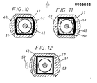
- Fig. 10 and 11 show the rotor and the carrier of the pump in two different relative positions,
- Fig. 12 shows a modified embodiment of the rotor according to Fig. 10 and 11, and
- Fig. 13-16 illustrate a further modified embodiment of the rotor and the carrier as a sectional view and an elevational view and in two different positions.
- On the
drawings numeral 11 indicates a pump housing,numeral 12 the bottom element of the pump housing, numeral 13 a movement transmission mechanism situated within the pump housing andnumeral 14 indicates a diaphragm which is constricted between adiaphragm plate 15 and theworking chamber element 16 of the pump. Themovement transmission mechanism 13 is fixed at thediaphragm 14 which mechanism comprises awobble plate 17, which via spacing means 18 is connected to thediaphragm 14. In the example of embodiment shown the pump comprises four workingchambers 19a-d, but several or even less chambers can be provided. The minimum number is however restricted to two. - The working chambers 19 are at the top thereof defined by the
diaphragm 14, at their sides and partly at the lower part thereof by theworking chamber element 16 and at the lower part thereof by anintermediate wall element 20, which also forms a delimiting means between theinlet chamber 21 and theoutlet chamber 22 of the pump. Between theworking chamber element 16 and the intermediate wall element 20 awalve diaphragm 23 is constricted, in whichflaps 25 are formed just in front of theinlet openings 24 in the intermediate wall element. In the central part of theelement 16outlet openings 27 are provided in thebottom 26 of the working chamber. Thebottom 26 of the working chambers 19 occupies only about half the surface thereof and as to the rest this is occupied by arecess 28 situated just in front of theinlet openings 24 of theintermediate wall element 20. - The central middle portion of the
element 16 is provided on its lower side with a cap-shaped cavity or recess 29, against which arubber disk 30 is placed, which in cooperation with theoutlet openings 27 acts as non-return valves. - In the example of embodiment shown the diaphragm pump is provided with a
non-return valve plate 31 havingoutlet openings 32 and which plate can be tightly pressed into acentral recess 33 in theintermediate wall element 20. On the lower side of thenon-return valve 31 between thebottom element 12 of the pump housing and theintermediate wall element 20 is tightly clamped anangular rubber plate 34, which together with theoutlet openings 32 forms four non-return valves. In accordance with this embodiment the pump can thus work as a pressure pump and if thenon-return plate 31 together with therubber ring 34 are removed a draining pump is obtained having a great lifting capacity but a small pressure on the outlet side. - In the
bottom element 12 of the pump housing acircular recess 35 is provided, to which tangentially is connected anoutlet port 36 to anoutlet stud 37. On a level above therecess 35 anangular step 38 is formed in thebottom element 12 of the pump housing, to which step also tangentially is connected aninlet port 39, which transcends into aninlet stud 40. As previously mentioned theintermediate element 20 forms an inner delimiting means for theinlet chamber 21, the outer limit of which being formed by thestep 38 and theside wall 41 of thebottom element 12. In one side wall of the bottom element 12 acavity 42 which is outwardly opened is provided against which adiaphragm 43 is in contact and outside this apressure switch 44. - As already mentioned the
movement transmission mechanism 13 consists of awobble plate 17, which via spacing means 18 is connected to the diaphragm for forming four working chambers 19. Thewobble plate 17 is provided with a central guide shaft which via a roll bearing 46 is connected to acarrier 47. Thecarrier 47 which substantially is rectangular is axially displacable but unrotatably connected with arotor 48 which is driven by theshaft 50 of thepump motor 49. In therotor 48 an elongated groove or acavity 51 is provided, which either per se can be excentric in relation to thedriving shaft 50 or can be provided with control means 52 for a variable adjustment of the excentricity of theguide shaft 45 in relation to thedriving shaft 50. In rotating therotor 48 theguide shaft 45 will thus be imparted a movement along a circular path, i.e. the guide shaft performs a movement along the generatrics to a cone, the tip of the cone being directed towards thediaphragm 14. Due to this the wobble plate will perform a wobbling movement in such a way that the working chambers 19 temporarily and alternately function as pressure chambers and suction chambers. - To reduce breakdown risks in case of extreme counter pressures the carrier can be provided with
resilient means 53 formed to hold the carrier in a preset excentric position in relation to the drivingshaft 50, as appears from Fig. 10. In case of an overloading theguide shaft 45 endeavours to reduce the excentricity and will then perform a contact pressure against the resilient means, which for example can comprise a rubber coating surrounding the carrier. In Fig. 11 there is shown a position wherein the center of the guide shaft coincides with the center of the driving shaft, which means that no pumping effect is performed. As soon as the counter pressure has been overcome the carrier can return to its initial position. - If as the pump motor a 220 V single-phase motor shall be used this cannot in starting be directly loaded with full effect and in such a case it may be convenient to provide the
carrier 47 with acentrifugal weight 54, which brings about, as appears from Fig. 13-16, together with acentering means 53, for example two rubber blocks, that the electric motor can start with theguide shaft 45 situated axially in front of thedriving shaft 50, that is without moving the wabble plate and thus without any appreciable load. In accelerating to normal speed the carrier will be gradually displaced due to the centrifugal force in such a way that the end of the guide shaft will be excentric in relation to thedriving shaft 50. When the motor is stopped thecarrier 47 will return to its original position by way of the centering means 53. - In order to obtain a more regular operation pressure equalizing means, for example pieces of foamed rubber having closed cells are provided in the
inlet chambers 21 as well as in theoutlet chambers 22. In case of pressure impacts these soft pressure equalizing means will thus absorb these impacts so that a regular and a substantially vibration free operation is obtained. Due to the fact that thediaphragm 14 only has to perform reciprocal movements this can be made of fabric, while the remaining diaphragms which all have sealing functions consist of rubber. The special design of the working chambers their large inlet- and outlet openings and the special construction of the valve diaphragms result in the fact that also relatively large impurities can pass through the pump without sealing problems. As already mentioned the pump can be changed in a very simple way from a pressure pump to a draining pump by removing thenon-return valve plate 31 with its pertainingvalve rubber plate 34. By way of the control means 52 the capacity of the pump can be changed in a very simple way. The whole pump can be manufactured in a convenient plastics material and is thus acid resistant and due to thediaphragm 14 also completely separated from the electric motor. - The invention is not restricted to the embodiments shown above but several modifications are possible within the scope of the following claims.
Claims (6)
that the wobble plate (17) is provided with a central guide shaft (45), which is adjustable in different sloping positions in relation to the driving shaft (50) of the pump, and on the shaft end of which a carrier (47) is rotatably journalled, which is axially displacable but unrotatably connected with a rotor (48) provided on the driving shaft (50) of the pump.
that the carrier (47) by way of a control means (52) is displacable in a groove (51) or the like in the rotor (48) substantially normal to the driving shaft (50) of the pump from a position in which the guide shaft (45) and the driving shaft (50) are centered in relation to each other (the stroke of the diaphragm is zero) to a more or less excentric position (increasing or reducing stroke of the diaphragm).
that the carrier (47) by at least one resilient means (53) is hold in its preset excentric position, which resilient means (53) in exceeding the spring force, in case of for example too great counter pressures in the pump, allows the carrier (47) to reduce the excentricity.
that the carrier (47) by way of at least one resilient means (53) is provided to center the guide shaft (45) in relation to the driving shaft (50) and that the carrier (47) is formed with a centrifugal weight (54) which during acceleration to normal operation speed by the centrifugal force brings the end of the guide shaft to a preset excentricity.
that an inlet chamber (21) and an outlet chamber (22) of the pump are separated from each other by a removable intermediate wall element (20) provided with inlet openings (24) and formed as a site for a non-return valve diaphragm (25).
that a non-return valve plate (31) is removably provided in the central part of the intermediate wall element (20) situated within the outlet chamber (22).
Priority Applications (1)
| Application Number | Priority Date | Filing Date | Title |
|---|---|---|---|
| AT82850109T ATE15252T1 (en) | 1981-05-13 | 1982-05-12 | DIAPHRAGM PUMP. |
Applications Claiming Priority (2)
| Application Number | Priority Date | Filing Date | Title |
|---|---|---|---|
| SE8103002 | 1981-05-13 | ||
| SE8103002A SE446353B (en) | 1981-05-13 | 1981-05-13 | Diaphragm Pump |
Publications (3)
| Publication Number | Publication Date |
|---|---|
| EP0065938A2 true EP0065938A2 (en) | 1982-12-01 |
| EP0065938A3 EP0065938A3 (en) | 1983-01-26 |
| EP0065938B1 EP0065938B1 (en) | 1985-08-28 |
Family
ID=20343816
Family Applications (1)
| Application Number | Title | Priority Date | Filing Date |
|---|---|---|---|
| EP82850109A Expired EP0065938B1 (en) | 1981-05-13 | 1982-05-12 | A diaphragm pump |
Country Status (7)
| Country | Link |
|---|---|
| US (1) | US4486151A (en) |
| EP (1) | EP0065938B1 (en) |
| JP (1) | JPS5815779A (en) |
| AT (1) | ATE15252T1 (en) |
| AU (1) | AU545346B2 (en) |
| DE (1) | DE3265791D1 (en) |
| SE (1) | SE446353B (en) |
Cited By (6)
| Publication number | Priority date | Publication date | Assignee | Title |
|---|---|---|---|---|
| US4507058A (en) * | 1983-12-20 | 1985-03-26 | Carr-Griff, Inc. | Wobble plate pump and drive mechanism therefor |
| US4515531A (en) * | 1982-09-14 | 1985-05-07 | Erich Roser | Swash ring driven diaphragm pump |
| US4797069A (en) * | 1987-06-03 | 1989-01-10 | Product Research And Development | Pump with variable angle wobble plate |
| FR2690621A1 (en) * | 1992-04-29 | 1993-11-05 | Chronotec | Friction-free infusion pump system. |
| AU701095B1 (en) * | 1998-08-14 | 1999-01-21 | Seong-Chul Kim | Diaphragm pump |
| US6623245B2 (en) | 2001-11-26 | 2003-09-23 | Shurflo Pump Manufacturing Company, Inc. | Pump and pump control circuit apparatus and method |
Families Citing this family (24)
| Publication number | Priority date | Publication date | Assignee | Title |
|---|---|---|---|---|
| US4557669A (en) * | 1984-09-04 | 1985-12-10 | Vanderjagt John A | Pumping apparatus |
| US4614481A (en) * | 1985-06-10 | 1986-09-30 | Vanderjagt John A | Pump with replaceable cartridge |
| US4801249A (en) * | 1986-06-09 | 1989-01-31 | Ohken Seiko Co., Ltd. | Small-sized pump |
| US4723894A (en) * | 1986-12-03 | 1988-02-09 | Transamerica Delaval, Inc. | Low-pressure air pump |
| US5476367A (en) * | 1994-07-07 | 1995-12-19 | Shurflo Pump Manufacturing Co. | Booster pump with sealing gasket including inlet and outlet check valves |
| US5632607A (en) * | 1995-11-01 | 1997-05-27 | Shurflo Pump Manufacturing Co. | Piston and valve arrangement for a wobble plate type pump |
| US5791882A (en) * | 1996-04-25 | 1998-08-11 | Shurflo Pump Manufacturing Co | High efficiency diaphragm pump |
| US6048183A (en) * | 1998-02-06 | 2000-04-11 | Shurflo Pump Manufacturing Co. | Diaphragm pump with modified valves |
| US6371740B1 (en) * | 1999-05-11 | 2002-04-16 | Jansen's Aircraft Systems Controls, Inc. | Jet engine fuel delivery system with non-pulsating diaphragm fuel metering pump |
| JP2003120521A (en) * | 2001-10-10 | 2003-04-23 | Mitsumi Electric Co Ltd | Small pump |
| US6715994B2 (en) | 2001-11-12 | 2004-04-06 | Shurflo Pump Manufacturing Co., Inc. | Bilge pump |
| US7083392B2 (en) | 2001-11-26 | 2006-08-01 | Shurflo Pump Manufacturing Company, Inc. | Pump and pump control circuit apparatus and method |
| WO2003100253A1 (en) * | 2002-05-24 | 2003-12-04 | Keith Larke | An improved fluid pump |
| US7013793B2 (en) * | 2004-03-22 | 2006-03-21 | Itt Manufacturing Enterprises | Diaphragm mounting method for a diaphragm pump |
| TWM292016U (en) * | 2006-01-06 | 2006-06-11 | Tricore Corp | Air pump with reduced sound produced during air passage |
| TWI548827B (en) | 2009-11-09 | 2016-09-11 | 高元管理股份有限公司 | Diaphragm and diaphragm valve |
| JP5770458B2 (en) * | 2010-11-30 | 2015-08-26 | アルバック機工株式会社 | Pump system |
| CN103717899B (en) * | 2011-07-11 | 2016-05-18 | 应研精工株式会社 | Membrane pump |
| EP2554846B1 (en) * | 2011-08-04 | 2013-07-31 | Okenseiko Co., Ltd. | Diaphragm pump |
| TWI588357B (en) * | 2014-05-20 | 2017-06-21 | 徐兆火 | Vibration-reducing structure for four-compression-chamber diaphragm pump |
| WO2015179121A1 (en) * | 2014-05-20 | 2015-11-26 | Chen, Chung-Chin | Roundel structure for four-compression-chamber diaphragm pump with multiple effects |
| GB2527321A (en) * | 2014-06-17 | 2015-12-23 | Tcs Micropumps Ltd | Fluid pump |
| US9970429B2 (en) * | 2014-07-16 | 2018-05-15 | Flowserve Management Company | Diaphragm pump |
| WO2021158448A1 (en) * | 2020-02-04 | 2021-08-12 | Alphinity, Llc | Pump and combination pump/mixer device |
Citations (3)
| Publication number | Priority date | Publication date | Assignee | Title |
|---|---|---|---|---|
| US2991723A (en) * | 1958-02-05 | 1961-07-11 | Gen Motors Corp | Wobble plate diaphragm pump |
| GB930088A (en) * | 1959-02-19 | 1963-07-03 | Raoul Joseph Paul Sarrazin | Improvements in hydraulic swash plate pumps and motors |
| US4153391A (en) * | 1975-05-29 | 1979-05-08 | Carr-Griff, Inc. | Triple discharge pump |
Family Cites Families (11)
| Publication number | Priority date | Publication date | Assignee | Title |
|---|---|---|---|---|
| CA450357A (en) * | 1948-08-03 | Olaer Patent Cy | Pump | |
| US2797647A (en) * | 1954-01-19 | 1957-07-02 | Detroit Harvester Co | Hydraulic pump |
| US2957421A (en) * | 1954-03-17 | 1960-10-25 | Bendix Corp | Fuel supply pump for prime movers |
| US2983153A (en) * | 1957-01-10 | 1961-05-09 | Gen Motors Corp | Fluid pump control mechanism |
| US3512178A (en) * | 1967-04-24 | 1970-05-12 | Parker Hannifin Corp | Axial piston pump |
| US3498229A (en) * | 1967-11-01 | 1970-03-03 | Dake Corp | Hydraulic pump assembly |
| JPS4921405B1 (en) * | 1970-12-30 | 1974-05-31 | ||
| CS169273B1 (en) * | 1974-03-15 | 1976-07-29 | ||
| CS172656B1 (en) * | 1974-06-24 | 1977-01-28 | ||
| US4077269A (en) * | 1976-02-26 | 1978-03-07 | Lang Research Corporation | Variable displacement and/or variable compression ratio piston engine |
| US4396357A (en) * | 1981-04-06 | 1983-08-02 | Product Research And Development | Diaphragm pump with ball bearing drive |
-
1981
- 1981-05-13 SE SE8103002A patent/SE446353B/en not_active IP Right Cessation
-
1982
- 1982-05-11 US US06/377,173 patent/US4486151A/en not_active Expired - Lifetime
- 1982-05-11 AU AU83601/82A patent/AU545346B2/en not_active Ceased
- 1982-05-12 EP EP82850109A patent/EP0065938B1/en not_active Expired
- 1982-05-12 DE DE8282850109T patent/DE3265791D1/en not_active Expired
- 1982-05-12 AT AT82850109T patent/ATE15252T1/en not_active IP Right Cessation
- 1982-05-12 JP JP57078489A patent/JPS5815779A/en active Pending
Patent Citations (3)
| Publication number | Priority date | Publication date | Assignee | Title |
|---|---|---|---|---|
| US2991723A (en) * | 1958-02-05 | 1961-07-11 | Gen Motors Corp | Wobble plate diaphragm pump |
| GB930088A (en) * | 1959-02-19 | 1963-07-03 | Raoul Joseph Paul Sarrazin | Improvements in hydraulic swash plate pumps and motors |
| US4153391A (en) * | 1975-05-29 | 1979-05-08 | Carr-Griff, Inc. | Triple discharge pump |
Cited By (8)
| Publication number | Priority date | Publication date | Assignee | Title |
|---|---|---|---|---|
| US4515531A (en) * | 1982-09-14 | 1985-05-07 | Erich Roser | Swash ring driven diaphragm pump |
| US4507058A (en) * | 1983-12-20 | 1985-03-26 | Carr-Griff, Inc. | Wobble plate pump and drive mechanism therefor |
| US4797069A (en) * | 1987-06-03 | 1989-01-10 | Product Research And Development | Pump with variable angle wobble plate |
| FR2690621A1 (en) * | 1992-04-29 | 1993-11-05 | Chronotec | Friction-free infusion pump system. |
| WO1993021976A1 (en) * | 1992-04-29 | 1993-11-11 | Chronotec S.A.R.L. | Friction-free infusion pump system |
| US5458469A (en) * | 1992-04-29 | 1995-10-17 | Hauser; Jean-Luc | Friction-free infusion pump system |
| AU701095B1 (en) * | 1998-08-14 | 1999-01-21 | Seong-Chul Kim | Diaphragm pump |
| US6623245B2 (en) | 2001-11-26 | 2003-09-23 | Shurflo Pump Manufacturing Company, Inc. | Pump and pump control circuit apparatus and method |
Also Published As
| Publication number | Publication date |
|---|---|
| JPS5815779A (en) | 1983-01-29 |
| ATE15252T1 (en) | 1985-09-15 |
| EP0065938A3 (en) | 1983-01-26 |
| SE8103002L (en) | 1982-11-14 |
| SE446353B (en) | 1986-09-01 |
| US4486151A (en) | 1984-12-04 |
| EP0065938B1 (en) | 1985-08-28 |
| DE3265791D1 (en) | 1985-10-03 |
| AU8360182A (en) | 1982-11-18 |
| AU545346B2 (en) | 1985-07-11 |
Similar Documents
| Publication | Publication Date | Title |
|---|---|---|
| EP0065938A2 (en) | A diaphragm pump | |
| JPS56101092A (en) | Compressor | |
| US4551080A (en) | Variable displacement sliding vane pump/hydraulic motor | |
| US5124038A (en) | Apparatus for separating and recovering floating liquid | |
| US3994638A (en) | Oscillating rotary compressor | |
| EP0282358A3 (en) | Improved inlet for a positive displacement pump | |
| US3536426A (en) | Gear pump having eccentrically arranged internal and external gears | |
| KR20040029171A (en) | Variable-delivery vane pump | |
| US5201643A (en) | Compression machine | |
| US2671411A (en) | Rotary pump or motor | |
| US4716726A (en) | Adjustable rotary vane pump | |
| US4137826A (en) | Piston pump | |
| ES8702804A1 (en) | Maintaining liquid level in a centrifugal separator. | |
| US1986454A (en) | Gas and vapor compressor | |
| US4229150A (en) | Anti-rotation arrangement for nutating fluid device | |
| US3600108A (en) | Rotary pump | |
| US4188176A (en) | Variable displacement rotary fluid energy converter | |
| US4371217A (en) | Hydrostatic sliding element | |
| SU1138541A1 (en) | Centrifugal pump relieving device | |
| WO1995012758A1 (en) | Positive displacement pump or motor | |
| US3602614A (en) | Positive displacement pump | |
| SU687280A1 (en) | Positive-displacement hydraulic drive | |
| US3900942A (en) | Method of forming a rotary motor or pump | |
| US3437049A (en) | Hydraulic pump and compressor | |
| US3266253A (en) | Variable speed hydraulic transmission |
Legal Events
| Date | Code | Title | Description |
|---|---|---|---|
| PUAI | Public reference made under article 153(3) epc to a published international application that has entered the european phase |
Free format text: ORIGINAL CODE: 0009012 |
|
| PUAL | Search report despatched |
Free format text: ORIGINAL CODE: 0009013 |
|
| AK | Designated contracting states |
Designated state(s): AT BE CH DE FR GB IT NL |
|
| AK | Designated contracting states |
Designated state(s): AT BE CH DE FR GB IT LI NL |
|
| 17P | Request for examination filed |
Effective date: 19830715 |
|
| ITF | It: translation for a ep patent filed |
Owner name: FIAMMENGHI - DOMENIGHETTI |
|
| GRAA | (expected) grant |
Free format text: ORIGINAL CODE: 0009210 |
|
| AK | Designated contracting states |
Designated state(s): AT BE CH DE FR GB IT LI NL |
|
| REF | Corresponds to: |
Ref document number: 15252 Country of ref document: AT Date of ref document: 19850915 Kind code of ref document: T |
|
| REF | Corresponds to: |
Ref document number: 3265791 Country of ref document: DE Date of ref document: 19851003 |
|
| ET | Fr: translation filed | ||
| PGFP | Annual fee paid to national office [announced via postgrant information from national office to epo] |
Ref country code: AT Payment date: 19860515 Year of fee payment: 5 |
|
| PLBE | No opposition filed within time limit |
Free format text: ORIGINAL CODE: 0009261 |
|
| STAA | Information on the status of an ep patent application or granted ep patent |
Free format text: STATUS: NO OPPOSITION FILED WITHIN TIME LIMIT |
|
| 26N | No opposition filed | ||
| PGFP | Annual fee paid to national office [announced via postgrant information from national office to epo] |
Ref country code: NL Payment date: 19870531 Year of fee payment: 6 |
|
| PG25 | Lapsed in a contracting state [announced via postgrant information from national office to epo] |
Ref country code: AT Effective date: 19880512 |
|
| PG25 | Lapsed in a contracting state [announced via postgrant information from national office to epo] |
Ref country code: LI Effective date: 19880531 Ref country code: CH Effective date: 19880531 |
|
| BERE | Be: lapsed |
Owner name: VEIKKO KORHONEN-WESALA Effective date: 19880531 |
|
| REG | Reference to a national code |
Ref country code: CH Ref legal event code: PL |
|
| PG25 | Lapsed in a contracting state [announced via postgrant information from national office to epo] |
Ref country code: BE Effective date: 19890531 |
|
| PG25 | Lapsed in a contracting state [announced via postgrant information from national office to epo] |
Ref country code: NL Effective date: 19891201 |
|
| NLV4 | Nl: lapsed or anulled due to non-payment of the annual fee | ||
| PGFP | Annual fee paid to national office [announced via postgrant information from national office to epo] |
Ref country code: FR Payment date: 19960409 Year of fee payment: 15 |
|
| PGFP | Annual fee paid to national office [announced via postgrant information from national office to epo] |
Ref country code: DE Payment date: 19960415 Year of fee payment: 15 |
|
| PGFP | Annual fee paid to national office [announced via postgrant information from national office to epo] |
Ref country code: GB Payment date: 19960418 Year of fee payment: 15 |
|
| PG25 | Lapsed in a contracting state [announced via postgrant information from national office to epo] |
Ref country code: GB Effective date: 19970512 |
|
| GBPC | Gb: european patent ceased through non-payment of renewal fee |
Effective date: 19970512 |
|
| PG25 | Lapsed in a contracting state [announced via postgrant information from national office to epo] |
Ref country code: FR Free format text: LAPSE BECAUSE OF NON-PAYMENT OF DUE FEES Effective date: 19980130 |
|
| PG25 | Lapsed in a contracting state [announced via postgrant information from national office to epo] |
Ref country code: DE Free format text: LAPSE BECAUSE OF NON-PAYMENT OF DUE FEES Effective date: 19980203 |
|
| REG | Reference to a national code |
Ref country code: FR Ref legal event code: ST |