EP0065682B1 - Omnidirectional display device - Google Patents
Omnidirectional display device Download PDFInfo
- Publication number
- EP0065682B1 EP0065682B1 EP82103952A EP82103952A EP0065682B1 EP 0065682 B1 EP0065682 B1 EP 0065682B1 EP 82103952 A EP82103952 A EP 82103952A EP 82103952 A EP82103952 A EP 82103952A EP 0065682 B1 EP0065682 B1 EP 0065682B1
- Authority
- EP
- European Patent Office
- Prior art keywords
- display device
- visible
- viewing
- cylindrical
- observation
- Prior art date
- Legal status (The legal status is an assumption and is not a legal conclusion. Google has not performed a legal analysis and makes no representation as to the accuracy of the status listed.)
- Expired
Links
Images


Classifications
-
- G—PHYSICS
- G09—EDUCATION; CRYPTOGRAPHY; DISPLAY; ADVERTISING; SEALS
- G09F—DISPLAYING; ADVERTISING; SIGNS; LABELS OR NAME-PLATES; SEALS
- G09F19/00—Advertising or display means not otherwise provided for
- G09F19/12—Advertising or display means not otherwise provided for using special optical effects
-
- G—PHYSICS
- G09—EDUCATION; CRYPTOGRAPHY; DISPLAY; ADVERTISING; SEALS
- G09F—DISPLAYING; ADVERTISING; SIGNS; LABELS OR NAME-PLATES; SEALS
- G09F13/00—Illuminated signs; Luminous advertising
- G09F13/04—Signs, boards or panels, illuminated from behind the insignia
- G09F13/0418—Constructional details
- G09F13/0472—Traffic signs
-
- G—PHYSICS
- G09—EDUCATION; CRYPTOGRAPHY; DISPLAY; ADVERTISING; SEALS
- G09F—DISPLAYING; ADVERTISING; SIGNS; LABELS OR NAME-PLATES; SEALS
- G09F13/00—Illuminated signs; Luminous advertising
- G09F13/34—Illuminated signs; Luminous advertising with light sources co-operating with movable members, e.g. with shutters to cover or uncover the light source
- G09F13/36—Illuminated signs; Luminous advertising with light sources co-operating with movable members, e.g. with shutters to cover or uncover the light source co-operating with rotating screening means
Definitions
- the invention relates to a display device for all-round representation of visible objects, such as numbers, fonts, characters, pictures or the like, with a plurality of visual elements designed as viewing optics, which are arranged next to one another on a curved surface and to which a visual object is assigned.
- a known display device for all-round display is, for example, a clock that rotates continuously around a vertical axis, as is the case in public places, on the roofs of stations or the like. is occasionally used to display the time on all sides.
- a rotating clock has the disadvantage that the time display is not visible from all sides at the same time, so that the viewer who wants to know the time has to wait a certain amount of time until the clock face has turned in its viewing direction .
- This time can be shortened by turning the clock faster, but this shortens the time available to the viewer to perceive the time display, so that the viewer becomes irritated and insecure because of the relatively short perception time, whether he has read the time display correctly, which in turn means that he waits until the dial has rotated in his direction of view a second time to ensure that he has actually read the time display correctly.
- the advantage of shortening the waiting time which is required for the dial to rotate in the viewing direction of the viewer, is then nullified by the then arising need to make sure that the time display reading is correct.
- the drum must be large enough that in such a position he can recognize the two signs adjacent to the space he is looking at, otherwise he will not be able to see any of them would recognize these two characters correctly, i.e. the display would not be recognizable from such a direction.
- the object of the invention in contrast, is to provide a display device of the type mentioned at the outset, with which any desired display objects, such as numbers, fonts, characters, images or the like, can be made completely identically visible from all view sides, at least in one plane, without the display device and / or the viewing object having to be rotated, and which, moreover, is free from further of the disadvantages mentioned above, that is to say in particular requires a relatively small amount of space, based on a predetermined recognizability distance of the viewing object.
- any desired display objects such as numbers, fonts, characters, images or the like
- each viewing optic is essentially assigned an identical or similar viewing object; that each viewing optics makes only a sub-area of the viewing object visible, regardless of the direction of supervision, and the sub-areas made visible by a group of adjacent viewing optics are combined to form an overall representation of the viewing object; and that each viewing optic makes a partial area of the viewing object dependent on the direction of supervision visible, so that depending on the direction of supervision, the partial areas made visible by a respective other group of adjacent viewing optics make up the overall representation of the viewing object, the individual groups preferably being adjacent to one another Viewing optics, each of which gives an overall representation of the viewing object, comprise all or essentially all those viewing optics of the display device that are visible from the direction of supervision.
- a particularly preferred embodiment of the display device according to the invention is characterized in that the curved surface is an isometric surface, i.e. a one-dimensionally rounded surface or a surface which can be unwound into a plane, preferably a cylindrical surface of a cylinder having a rounded cross section, in particular the surface of a cylinder with a circular or elliptical cross section.
- the viewing optics can be gaps; further preferred viewing optics are cylindrical, Fresnel or gradient lenses.
- gaps are provided as viewing optics, then these are preferably designed and aligned such that their longitudinal direction is perpendicular to the curvature gradient of the curved surface.
- Fresnel or gradient lenses as viewing optics are designed and arranged so that they have focal lines that run perpendicular to the direction of curvature of the curved surface.
- the curved surface is the lateral surface of a cylinder which is circular or elliptical in cross section
- the gaps with their longitudinal directions or the focal lines of the cylinder, Fresnel or gradient lenses preferably extend parallel to the cylinder axis.
- a preferred embodiment of the invention is further characterized in that the viewing objects are provided on the outer surface or inner surface of a base body that supports or forms the viewing optics, in particular a cylindrical base body.
- a base body that supports or forms the viewing optics
- the wall thickness of this internally hollow base body is dimensioned such that its inner surface coincides with the focal points or focal lines of the viewing optics.
- Another embodiment of the display device according to the invention is characterized in that the view object is rotatably provided in the center of a base body supporting or forming the viewing optics, in particular a cylindrical base body, so that an image of the view object is in each case at very short intervals on each of the individual ones Imaging optics can be designed consecutively, that is, each imaging optic is assigned the same visual object in chronological succession, the time interval being so short that an observer no longer perceives this chronological sequence.
- the display device such that the curved surface is a three-dimensionally rounded surface, in particular a spherical or ellipsoid surface, on which the viewing optics are arranged next to one another as individual lenses or diaphragm openings.
- visible objects such as numbers, fonts, characters, pictures or the like. can be made visible from practically all spatial supervisory directions, which is particularly advantageous, for example, in large stairwells of subway stations or from stations with platforms provided on several floors or in airport buildings with several traffic levels.
- the basic body carrying or forming the viewing optics can be rotated for all-round display of lettering or moving images.
- the display device enables any displayed objects, such as numbers, fonts, characters, pictures or the like. can be seen from all sides completely the same or - in the case of moving pictures - essentially the same.
- the viewer can walk around the display device or, if it is a smaller display device that is directly accessible to the viewer, in particular can be held in his hand, rotate the display device, the display always sees completely or - in the case of moving images - essentially the same. Even if many viewers stand around the display device, they will all see the viewing object in the same way.
- the display device enables, for example, the construction of clocks and signs, such as traffic signs, which can be read from an angle of 360 °; standing fonts or pictures can be attached to rotating display devices, which are preferably drum-shaped. As already indicated, motion sequences can also be represented, and these take place when the display device rotates, in particular a drum-shaped display device, as in the cinema.
- each observation lens is "essentially" assigned an identical or similar view object, means that although each observation lens can be assigned exactly one view object, it is also possible for a relatively large number of observation lenses to have a relatively large, but also not assign exactly the same number of view objects; in the former case, the solid angle taken up by a single visual object is exactly the same as the solid angle captured by the individual viewing optics, while in the latter case these solid angles are somewhat different, so that when the display device is rotated, the display moves in the direction of rotation or opposite to the direction of rotation leaves.
- Each viewing optics A or: A o to A 47 is assigned an identical or similar viewing object, which is denoted by B in FIG. 1, while these viewing objects are successively provided with the reference symbols B o to B 47 in FIG. 2.
- These viewing objects are arranged in the supervisory direction behind the viewing optics A or A o to A 4 , and can, for example, numbers, fonts, characters, pictures or the like. be.
- the viewing optics A and A 0 to A are 47 cylindrical lenses, and the curved surface F is the outer surface of a cylinder with a circular cross section.
- the viewing optics A or A o to A 47 that is to say the cylindrical lenses in the present case, extend parallel to the longitudinal axis 0 of the cylinder over the entire longitudinal extent thereof.
- the viewing optics A or A o to A 47 are components of an overall one-piece base body 2, which is made of transparent material, for example plastic, exists, the inner cavity of which is limited by the area F.
- each viewing lens A or A 0 to A 47 lies precisely on the curved surface F, that is, on the inner boundary surface of the transparent base body 2.
- the visible objects B and B 0 to B 47 are arranged on the curved surface F in this case.
- a cylindrical lens in the sense of the present invention is generally to be understood as an elongated lens which has any optically meaningful cross section perpendicular to the longitudinal axis or extension, and which has no curvature in the direction of its longitudinal axis or extension.
- a viewing object B 0 , B 1 ... B n in the form of an image is provided on the surface F under each observation lens A o , A 1 ... A n designed as a cylindrical lens. If a viewer now looks from a distance in the direction of supervision X onto the base body 2, which can also be referred to as a display drum, then he sees only the image parts Y i , Y 2 from a viewing object B o , B, ... B n . .. Y n , which lie in the focal lines of the cylindrical lenses.
- the principle of the display device is now based on the fact that the focal lines of the cylindrical lenses, or generally the viewing optics, in the direction of supervision X on the inner circumference of the display device or in the plane of the viewing objects, in the present case on the surface F, each by different distances ⁇ 0 , ⁇ 1 ... on from the center C o , C, ... C n are disengaged under the nth cylindrical lens. If, as stated, there is the same viewing object B 0 , B 1 ...
- this strip-like composition of the overall representation when viewed from the supervisory direction X1 given there means that this overall representation is generated by the viewing optics A 1 to A 25 which are dashed within the two parallel to the arrow X 1 Lines lie, that is, they are within the field of vision of an observer looking from this direction;
- the viewing optics A 13 correspond to the viewing optics A o of FIG. 3.
- the viewing optics A 25 correspond to the viewing optics A o in FIG. 3.
- the horizontal resolution of a display device is limited by the width and the number of effective cylindrical lenses and by the quality of the respective viewing object under each cylindrical lens.
- the number of effective cylindrical lenses is 2N + 1 if one designates N as the number of cylindrical lenses, each of which contributes to the formation of the overall representation on the right or left side of the central cylindrical lens A o . Since an image or view object strip contributed by a cylindrical lens to the overall display must not overlap the image or view object strip contributed by the adjacent cylindrical lens, the relationship must apply:
- the viewing angle at which the viewing object is seen through the respective cylindrical lens and which is labeled ⁇ n in FIG. 3 must not be greater than the critical angle of total reflection, ie the following must apply:
- ⁇ n is the angle at which the image or view object strip for the Nth cylinder lens contributed by the cylindrical lens AN is offset from the center C of the cylindrical lens as seen from axis 0 (in FIG. 3, ⁇ n is for the cylindrical lens shown on).
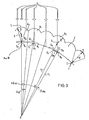
- FIG. 4 shows a number of 29 viewing objects in the form of an image strip which can be arranged behind 29 cylindrical lenses, whereupon the cylindrical lenses of this display device appearing in the field of view of a viewer each show the letter D.
- the information contained in each of these 29 visual objects consists, as can be seen in FIG. 4, of five vertical strips.
- each cylindrical lens can be regarded as the 0th cylindrical lens or as cylindrical lens A o in the sense of FIG. 3, the field of view of the display device from M viewing directions around the display device is identical if M means the number of cylindrical lenses on the circumference of the display device. Since the information strips of an image or visual object continue to have a certain width, the viewer also sees the same image from the intermediate supervisory directions.
- Gaps are also suitable as viewing optics, which becomes clear from FIG. 3 if corresponding gaps are used instead of the lenses, each of which only shows a strip of the viewing object from the direction of view X, this strip if the gaps are arranged there , where the vertices S of the lenses are located in FIG. 3, respectively offset by A i , Az ... An from the longitudinal center C 1 , C z ... C " .
- a display device can be produced from a one-piece base body, for example by milling the display device out of plexiglass tube and then polishing it. Rolling, casting and spraying processes can also be used to manufacture the display device.
- view objects as far as they are computationally realizable view objects, can be constructed using the formulas given above or derived for other viewing optics, drawn with the computing machine and reproduced.
- Image strips i.e. Strips that contain a plurality of visible objects side by side, such as corresponding to FIG. 4, are produced photographically:
- the image to be displayed with the display device is projected from a greater distance 10 onto a display device 12 which is rotatably mounted about its axis 11 and has no visible objects.
- This display device 12 can be, for example, a cylindrical lens drum, as is the main body 2 of FIG. 1.
- a photographic film 12 is inserted into the display device 12, specifically this photographic film is provided at the point at which the visual objects are later to be arranged; in the case of a base body 2 of FIG. 1 provided with cylindrical lenses, this photographic film 13 is inserted in such a way that its photographic layer lies against the surface F. The inserted film 13 is exposed to the projected image while the display device 12 is rotated several times about its axis 11.
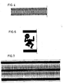
- the developed film strip 13 shows the finished viewing objects, that is to say the individual images compressed in the sense of FIG. 6 shows an example of a Jerusalemproji arrangementen on the display device 12 of Figure 5 by the optical system 9 of the image in the form of a dancing male holding his head in the hand shown, while the figure 7 the DAR 'of obtained film strip for the case reproduces that the display device 12 is a cylindrical lens drum of the type shown in FIG.
- the image of FIG. 6 which is very significantly compressed in the horizontal direction, in repeated repetition, so that the image strip reproduced in FIG. 7 can be used, for example, as an image strip containing 51 viewing objects for a cylindrical lens drum with 51 cylindrical lenses
- the cylindrical lens drum presents the viewer with the image shown in FIG. 6.
- a 7-segment display in which the seven segments can each be display elements of a number, which is provided under each cylindrical lens or other imaging optics, makes it possible, for example, to display a number with the display device.
- the viewing object can also be provided, for example, in the center of the display device or outside the display device, and an image of the viewing object can be supplied to each imaging optics, for example one cylindrical lens of a cylindrical lens drum, by projection or light guide.
- each imaging optics for example one cylindrical lens of a cylindrical lens drum
- the compressed viewing object can be projected onto the individual viewing optics, for example cylindrical lenses, from the inside of the display device in such short time intervals using a rotating periscope that the viewer sees the display flicker-free.
- a visual object does not necessarily have to be understood as an objective object, but can also be a projected, in particular flashed image, which, moreover, does not have to be assigned simultaneously in each viewing optics, but, as just stated, essentially every viewing optic is supplied in a very rapid sequence.
- the horizontally compressed images that are provided on the inner circumference of the display device have to represent the different movement phases.
- the visual field contains information from 2N + different image strips, i.e. that conventional cinema images that are not simply compressed can be provided horizontally and can be provided behind the viewing optics, for example behind the cylindrical lenses.
- the basic method explained above with reference to FIG. 5, can be used to produce an image strip comprising the individual visual objects, but with the special feature that the projection of the moving representation, which will later be reproduced with the display device, and the rotation the display device are executed synchronously.
- this film loop is projected with the imaging optics 9 of a cinema projector for moving images onto the display device 12, with one pass of the film loop having to correspond exactly to one revolution of the display device if it is on the film loop representation to be reproduced by means of one revolution of the display device.
- the synchronization it is also possible for the synchronization to take place in such a way that the display device executes several complete rotations during one pass of the cinema loop or, conversely, that the film loop executes several complete passages during one complete rotation of the display device.
- FIG. 8 illustrates an example of an image sequence which, when reproduced, shows males climbing a ladder.
- the sequence of images thus produced is placed in a corresponding display device, for example a cylindrical lens drum of the type shown in FIG. 1, and is allowed to roll over a table, the sequence of movements according to the film loop can be seen. This way you have a pocket cinema that is a beloved toy. If the number of viewing objects does not match the number of viewing optics of the display device, the display image is displaced transversely to the axis of the display device, for example to the drum axis 0 of FIG. 2, when the display device is rotated or around it. Also flickering effects, i. H. Light-dark effects can be obtained in this way.
- cylindrical Fresnel lenses is particularly recommended for large display devices, with the viewing objects, that is to say the image strip containing the viewing objects, for example, lying in the focal surface of these cylindrical Fresnel lenses.
- the principle of the display device can also be implemented in three dimensions with a lens-coated spherical surface.
- the display can then be seen from the full solid angle 4 ⁇ .
- the information may lie in concentric circles under the lenses.
- Preferred areas of application of the display device according to the invention are in particular the display of numbers and characters that are to be seen from all sides, for example in clocks, traffic signs, advertising signs, in board games that are on the table, warning signs in factory halls, displays on sports fields, etc.
- the above-mentioned application as a pocket cinema is not only suitable for toy purposes but also for advertising purposes.
- the modern display electronics can easily be used with a corresponding simple modification.
Abstract
Description
Die Erfindung betrifft eine Displayvorrichtung zur Rundumdarstellung von Sichtobjekten, wie Ziffern, Schriften, Zeichen, Bildern o.dgl., mit einer Mehrzahl von als Betrachtungsoptiken ausgebildeten Sichtelementen, die nebeneinander auf einer gekrümmten Fläche angeordnet sind und denen je ein Sichtobjekt zugeordnet ist.The invention relates to a display device for all-round representation of visible objects, such as numbers, fonts, characters, pictures or the like, with a plurality of visual elements designed as viewing optics, which are arranged next to one another on a curved surface and to which a visual object is assigned.
Eine bekannte Displayvorrichtung zur Rundumdarstellung ist zum Beispiel eine sich um eine vertikale Achse kontinuierlich drehende Uhr, wie sie auf öffentlichen Plätzen, auf Bahnhofsdächern o.dgl. zur Zeitanzeige nach allen Seiten hin gelegentlich verwendet wird. Eine solche sich drehende Uhr hat jedoch den Nachteil, dass die Zeitanzeige nicht gleichzeitig von allen Seiten her sichtbar ist, so dass der Betrachter, der die Uhrzeit wissen will, eine gewisse Zeitlang warten muss, bis sich das Ziffernblatt der Uhr in seine Sichtrichtung gedreht hat. Diese Zeit lässt sich zwar dadurch verkürzen, dass die Uhr schneller gedreht wird, wodurch jedoch die Zeitdauer, die dem Betrachter zum Wahrnehmen der Zeitanzeige zur Verfügung steht, verkürzt wird, so dass der Betrachter wegen der dann nur verhältnismässig kurzen Wahrnehmungszeit irritiert und unsicher wird, ob er die Zeitanzeige richtig abgelesen hat, was wiederum dazu führt, dass er abwartet, bis sich das Ziffernblatt ein zweites Mal in seine Sichtrichtung gedreht hat, um sich zu vergewissern, ob er die Zeitanzeige tatsächlich richtig abgelesen hat. Im Ergebnis wird daher der Vorteil des Verkürzens der Wartezeit, die erforderlich ist, bis sich das Ziffernblatt in die Sichtrichtung des Betrachters gedreht hat, durch die dann entstehende Notwendigkeit, sich über die Richtigkeit der Zeitanzeigeablesung zu vergewissern, aufgehoben.A known display device for all-round display is, for example, a clock that rotates continuously around a vertical axis, as is the case in public places, on the roofs of stations or the like. is occasionally used to display the time on all sides. However, such a rotating clock has the disadvantage that the time display is not visible from all sides at the same time, so that the viewer who wants to know the time has to wait a certain amount of time until the clock face has turned in its viewing direction . This time can be shortened by turning the clock faster, but this shortens the time available to the viewer to perceive the time display, so that the viewer becomes irritated and insecure because of the relatively short perception time, whether he has read the time display correctly, which in turn means that he waits until the dial has rotated in his direction of view a second time to ensure that he has actually read the time display correctly. As a result, the advantage of shortening the waiting time, which is required for the dial to rotate in the viewing direction of the viewer, is then nullified by the then arising need to make sure that the time display reading is correct.
Soll anstelle einer Zeitanzeige oder einer anderen sich laufend verändernden Anzeige lediglich ein allgemein bekanntes Zeichen, wie beispielsweise ein Werbungszeichen oder ein öffentliches Hinweiszeichen, auf diese Weise nach allen Seiten hin sichtbar gemacht werden, dann reicht zwar eine kurze Erkennungszeit aus, jedoch ist es in solchen Fällen aufwendig, diese Anzeige laufend zu drehen, und zwar insbesondere im Hinblick auf den laufenden Energieverbrauch, der sich hierdurch ergibt. Ausserdem bedeutet eine solche Lösung einen erheblichen wartungs- und anlagemässigen Aufwand, so dass sie sich für eine Vielzahl von Anwendungsfällen schon deswegen verbietet. Bringt man, um den Aufwand, das Zeichen drehen zu müssen, zu vermeiden, dieses Zeichen mehrfach auf der Aussenseite einer vieleckigen oder runden Trommel an, dann ergibt sich ein verhältnismässig grosser Raumaufwand hierfür, weil der Betrachter, wenn er von einer beliebigen Aufsichtsrichtung her auf diese Trommel sieht, auch gerade so stehen kann, dass er auf den Zwischenraum zwischen zwei benachbarten Zeichen blickt. Soll der Betrachter auch aus diesen Aufsichtsrichtungen her das jeweilige Zeichen einwandfrei erkennen können, dann muss die Trommel so gross sein, dass er in einer solchen Stellung die beiden an den Zwischenraum, auf den er blickt, angrenzenden Zeichen erkennen kann, da er andernfalls keines von dieses beiden Zeichen richtig erkennen würde, also die Anzeige aus einer solchen Richtung nicht erkennbar wäre.If, instead of a time display or another continuously changing display, only a generally known sign, such as an advertising sign or a public information sign, is to be made visible on all sides in this way, then a short recognition time is sufficient, but it is Cases expensive to turn this display continuously, especially with regard to the current energy consumption that results from this. In addition, such a solution means a considerable maintenance and system-related effort, so that it is therefore already forbidden for a large number of applications. If you put this sign several times on the outside of a polygonal or round drum, in order to avoid the effort of having to turn the sign, then this results in a relatively large amount of space for this, because the viewer, when looking up from any direction this drum sees, can also stand so that it looks at the space between two adjacent characters. If the viewer is to be able to recognize the respective sign correctly from these supervisory directions, then the drum must be large enough that in such a position he can recognize the two signs adjacent to the space he is looking at, otherwise he will not be able to see any of them would recognize these two characters correctly, i.e. the display would not be recognizable from such a direction.
Neben den vorstehend erwähnten beiden Anzeigearten, nämlich der Anzeige einer sich auf einem vorbestimmten Betrachtungsfeld laufend veränderlichen Konstellation, wie es zum Beispiel eine Zeitanzeige ist, und der Anzeige eines unveränderlichen Zeichens, wie eines Werbe- oder öffentlichen Hinweiszeichens, in Rundumdarstellung, ist es weiterhin erwünscht, ganze Schriftzüge oder sich bewegende Bilder, zum Beispiel für Werbezwecke, nach allen Seiten hin in Rundumdarstellung sichtbar zu machen:In addition to the above-mentioned two types of display, namely the display of a constellation that is constantly changing on a predetermined field of view, such as a time display, and the display of an unchangeable sign, such as an advertising or public information sign, in all-round representation, it is also desirable To make whole lettering or moving pictures, for example for advertising purposes, visible in all directions in all-round representation:
Wendet man im Falle eines Schriftzugs eine zylindrische Trommel an, auf die der Schriftzug rundum aufgebracht ist und die sich um ihre Zylinderachse dreht, dann lässt sich zwar dieser Schriftzug bei Wahl einer geeigneten Drehgeschwindigkeit von allen Radialrichtungen der Trommel her ablesen, jedoch ist zum einen eine verhältnismässig grosse Trommel erforderlich, weil der Betrachter wegen der Krümmung der Trommel sonst nur jeweils einen einzigen Buchstaben auf einmal unverzerrt wahrnehmen würde, wodurch die Lesbarkeit erheblich beeinträchtigt wäre; zum anderen wird aber auch bei im Verhältnis zur Buchstabengrösse gross gewählten Trommelabmessungen die Lesbarkeit trotzdem beeinträchtigt, weil der Betrachter wegen der Krümmung der Trommel zwangsweise stets einen gewissen verzerrten Schriftbereich dargeboten bekommt, der sich zu beiden Seiten des lesbaren mittleren Schriftbereichs anschliesst und störend wirkt.If, in the case of a lettering, a cylindrical drum is applied to which the lettering is applied all around and which rotates about its cylinder axis, then this lettering can be read from all radial directions of the drum when a suitable rotational speed is selected, but on the one hand there is one relatively large drum required because the viewer would otherwise perceive only one letter at a time undistorted due to the curvature of the drum, which would significantly impair readability; on the other hand, legibility is nevertheless impaired even when the drum dimensions are large in relation to the letter size, because the viewer is necessarily always presented with a certain distorted writing area due to the curvature of the drum, which adjoins both sides of the legible middle writing area and is annoying.
Wendet man zur Rundumdarstellung von bewegbaren Bildern das vorstehend genannte Prinzip der sich drehenden Trommel an, indem man eine im Querschnitt vieleckige Trommel verwendet, auf deren Flachseiten die darzustellenden Bilder in jeweils unterschiedlichen Bewegungsphasen aufgebracht sind, dann ergibt sich zusätzlich zu den eben in Verbindung mit der Darstellung von Schriftzügen genannten Schwierigkeiten die weitere Schwierigkeit, dass eine relativ sehr hohe Umdrehungsgeschwindigkeit dieser Trommel erforderlich ist, damit innerhalb von etwa einer Zwanzigstelsekunde für den jeweiligen Betrachter ein Bild durch ein anderes ersetzt wird; diese hohe Umdrehungsgeschwindigkeit führt bei den für eine grössere Betrachtungsentfernung erforderlichen grossen Trommelabmessungen zu Umfangsgeschwindigkeiten, aufgrund deren die Ausführung einer solchen Displayvorrichtung praktisch nicht sinnvoll wäre. Würde man dagegen eine feststehende Trommel verwenden, dann müsste jedes auf deren Umfang vorgesehene Bild für sich bewegbar sein, beispielsweise indem es jeweils mittels einer Projektionsvorrichtung als bewegliches Bild von innen her aufprojiziert würde. Auch in diesem Falle kommen hierzu die oben für die Rundumdarstellung von Schriftzügen genannten Nachteile hinzu, wobei hier die zwangsweise gleichzeitige Wahrnehmung von verzerrten benachbarten Bildern wegen des Sichbewegens der Bilder besonders irritierend wäre.If one uses the above-mentioned principle of the rotating drum for the all-round display of moving images, by using a drum with a polygonal cross-section, on the flat sides of which the images to be displayed are applied in different phases of movement, then in addition to those in connection with the Difficulty in displaying lettering, the further difficulty that a relatively very high rotational speed of this drum is required so that one image is replaced by another for the respective viewer within about a twentieth of a second; this high rotational speed leads to circumferential speeds in the case of the large drum dimensions required for a larger viewing distance, on the basis of which the implementation of such a display device would be practically not sensible. If one, however, use a fixed drum, would then have to be movable, for example by means of a respective g Projektionsvorrichtun would projected onto a moving image from the inside, each provided on the circumference of image itself. In this case, too, come the above for the all-round display of lettering mentioned disadvantages, whereby the forced simultaneous perception of distorted neighboring images would be particularly irritating due to the movement of the images.
Es sei an dieser Stelle klarstellend darauf hingewiesen, dass von den oben angegebenen unbefriedigenden Lösungsmöglichkeiten als Stand der Technik bisher nur die eingangs erwähnte, sich um eine Vertikalachse drehende Uhr anzusehen ist, die aus dem täglichen Leben her bekannt ist und bei der das Sichtelement lediglich eine plane Abdeckscheibe für das Ziffernblatt und die Zeiger ist, die das Sichtobjekt bilden. Dagegen gehören die anderen oben diskutierten Möglichkeiten einer Rundumdarstellung aufgrund des der Abfassung der vorliegenden Unterlagen zugrundegelegten Materials nicht zum Stand der Technik, sie haben vielmehr den Zweck, die Schwierigkeiten aufzuzeigen, die sich bei einer Rundumdarstellung von Zeichen, Schriftzügen, Bildern o.dgl. ergeben.It should be clarified at this point that of the above unsatisfactory possible solutions as the prior art, only the clock mentioned at the beginning, which rotates around a vertical axis, is known from everyday life and in which the viewing element is only one flat cover plate for the clock face and the hands that form the visible object. On the other hand, the other options discussed above for an all-round display are not part of the state of the art due to the material on which the present documents were based; surrender.
Weitere Displayvorrichtungen nach dem Stande der Technik, bei denen eine aufeinanderfolgende Rundumdarstellung durch rotierbare Teile erreicht wird, sind aus der US-A-3 686 781 und der GB-A-429 042 bekannt:
- Bei einer Displayvorrichtung nach der US-A-3 686 781 werden Bilder und Zeichen durch Zylinderstablinsen auf eine zylindrische opake Aussenhaut der Displayvorrichtung projiziert. Das Bild ist statisch und wechselt nur, wenn mechanische Verschiebungen am Display vorgenommen werden. Für den Beobachter wirkt das Bild wie auf eine zylindrische Trommel ortsfest aufprojiziert. Dreidimensionale Bilder und Filmszenen können nicht dargestellt werden, und das Bild folgt dem Beobachter nicht, wenn dieser um die Displayvorrichtung herumgeht und die zylindrische Trommel nicht mitgedreht wird. Dasselbe gilt für eine in der GB-A-429 042 beschriebene Displayvorrichtung, die eine trommelförmige Betrachtungsfläche hat, bei der jedoch eine opake Aussenhaut der Trommel fehlt, so dass das dargestellte Bild selbst in Aufsichtsrichtung nur aus bestimmten Sichtbarkeitszonen heraus erkennbar ist. Sowohl bei der Displayvorrichtung nach der US-A-3 686 781 als auch bei derjenigen nach der GB-A-429 042 befindet sich unter jeder Zylinderlinse nur ein kleiner Bildteil des jeweils dargestellten Bildes, und das Bild dreht sich mit der Displayvorrichtung mit.
- In a display device according to US-A-3 686 781, images and characters are projected through cylindrical rod lenses onto a cylindrical opaque outer skin of the display device. The picture is static and only changes if mechanical displacements are made on the display. To the observer, the image looks like being projected onto a cylindrical drum. Three-dimensional images and film scenes cannot be displayed, and the image does not follow the observer if he walks around the display device and the cylindrical drum is not rotated. The same applies to a display device described in GB-A-429 042, which has a drum-shaped viewing surface, but in which an opaque outer skin of the drum is missing, so that the image shown can only be seen from certain visibility zones, even in the direction of supervision. Both in the display device according to US-A-3 686 781 and in that according to GB-A-429 042 there is only a small part of the image of the image shown under each cylindrical lens, and the image rotates with the display device.
Schliesslich ist aus der US-A-4 195 910 eine Displayvorrichtung der eingangs genannten Art bekannt, bei der entweder mehrere Sichtelementgruppen, die um eine Quaderfläche herum vorgesehen sind, oder eine einzige Gruppe von Sichtelementen, die um eine Zylinder- oder Kugelfläche herum angeordnet sind, eine Rundumdarstellung bewirken, auch wenn keine Drehung erfolgt. Aber auch hier ist jedem als Betrachtungsoptik ausgebildeten Sichtelement, ebenso wie bei den Displayvorrichtungen nach der US-A-3 686 781 und der GB-A-429 042, nur ein kleiner Bildteil des gesamten darzustellenden Bildes als Sichtobjekt zugeordnet, der seinerseits für jedes Sichtelement ein anderer Bildteil ist, als er den übrigen Sichtelementen zugeordnet ist. Damit der Betrachter das ganze Bild aus unterschiedlichen Betrachtungsrichtungen sehen kann, ist es auch hier erforderlich, dass dieses Bild rotiert, zu welchem Zweck auch eine entsprechende Drehvorrichtung in der Displayvorrichtung nach der US-A-4 195 910 vorgesehen ist.Finally, from US-A-4 195 910 a display device of the type mentioned is known, in which either a plurality of viewing element groups, which are provided around a cuboid surface, or a single group of viewing elements, which are arranged around a cylindrical or spherical surface , cause an all-round display, even if there is no rotation. However, here too, as with the display devices according to US-A-3 686 781 and GB-A-429 042, each viewing element designed as viewing optics is assigned only a small image part of the entire image to be displayed as a viewing object, which in turn is for each viewing element is a different part of the picture than it is assigned to the other visual elements. So that the viewer can see the entire image from different viewing directions, it is also necessary here for this image to rotate, for which purpose a corresponding rotating device is also provided in the display device according to US Pat. No. 4,195,910.
Aufgabe der Erfindung ist es demgegenüber, eine Displayvorrichtung der eingangs genannten Art zu schaffen, mit der beliebig angezeigte Sichtobjekte, wie Ziffern, Schriften, Zeichen, Bilder o.dgl., zumindest in einer Ebene von allen Ansichtsseiten her völlig gleich sichtbar gemacht werden können, ohne dass ein Drehen der Displayvorrichtung und/oder des Sichtobjekts erforderlich ist, und die im übrigen frei von weiteren der vorstehend genannten Nachteile ist, also insbesondere einen verhältnismässig geringen Raumaufwand, bezogen auf eine vorbestimmte Erkennbarkeitsentfernung des Sichtobjekts, erfordert.The object of the invention, in contrast, is to provide a display device of the type mentioned at the outset, with which any desired display objects, such as numbers, fonts, characters, images or the like, can be made completely identically visible from all view sides, at least in one plane, without the display device and / or the viewing object having to be rotated, and which, moreover, is free from further of the disadvantages mentioned above, that is to say in particular requires a relatively small amount of space, based on a predetermined recognizability distance of the viewing object.
Die mit der Erfindung zur Verfügung gestellte Displayvorrichtung, die das ermöglicht, zeichnet sich dadurch aus, dass jeder Betrachtungsoptik im wesentlichen ein gleiches oder ähnliches Sichtobjekt zugeordnet ist; dass jede Betrachtungsoptik unabhängig von der Aufsichtsrichtung nur einen Teilbereich des Sichtobjekts sichtbar macht und sich die von einer Gruppe von einander benachbarten Betrachtungsoptiken sichtbar gemachten Teilbereiche zu einer Gesamtdarstellung des Sichtobjekts zusammensetzen; und dass jede Betrachtungsoptik einen jeweils von der Aufsichtsrichtung abhängigen Teilbereich des Sichtobjekts sichtbar macht, so dass sich je nach der Aufsichtsrichtung die von einer jeweils anderen Gruppe von einander benachbarten Betrachtungsoptiken sichtbar gemachten Teilbereiche zur Gesamtdarstellung des Sichtobjekts zusammensetzen, wobei vorzugsweise die einzelnen Gruppen von einander benachbarten Betrachtungsoptiken, welche jeweils eine Gesamtdarstellung des Sichtobjekts geben, alle oder im wesentlichen alle diejenigen Betrachtungsoptiken der Displayvorrichtung umfassen, die von der Aufsichtsrichtung her sichtbar sind.The display device provided by the invention, which makes this possible, is characterized in that each viewing optic is essentially assigned an identical or similar viewing object; that each viewing optics makes only a sub-area of the viewing object visible, regardless of the direction of supervision, and the sub-areas made visible by a group of adjacent viewing optics are combined to form an overall representation of the viewing object; and that each viewing optic makes a partial area of the viewing object dependent on the direction of supervision visible, so that depending on the direction of supervision, the partial areas made visible by a respective other group of adjacent viewing optics make up the overall representation of the viewing object, the individual groups preferably being adjacent to one another Viewing optics, each of which gives an overall representation of the viewing object, comprise all or essentially all those viewing optics of the display device that are visible from the direction of supervision.
Eine besonders bevorzugte Ausführungsform der erfindungsgemässen Displayvorrichtung zeichnet sich dadurch aus, dass die gekrümmte Fläche eine isometrische Fläche ist, d.h. eine eindimensional gerundete bzw. in eine Ebene abwikkelbare Fläche, und zwar vorzugsweise eine Zylinderfläche eines einen gerundeten Querschnitt aufweisenden Zylinders, insbesondere die Fläche eines Zylinders mit kreisförmigem oder elliptischem Querschnitt.A particularly preferred embodiment of the display device according to the invention is characterized in that the curved surface is an isometric surface, i.e. a one-dimensionally rounded surface or a surface which can be unwound into a plane, preferably a cylindrical surface of a cylinder having a rounded cross section, in particular the surface of a cylinder with a circular or elliptical cross section.
Die Betrachtungsoptiken können im einfachsten Falle Spalte sein; weitere bevorzugte Betrachtungsoptiken sind Zylinder-, Fresnel- oder Gradientenlinsen.In the simplest case, the viewing optics can be gaps; further preferred viewing optics are cylindrical, Fresnel or gradient lenses.
Wenn als Betrachtungsoptiken Spalte vorgesehen sind, dann sind diese vorzugsweise so ausgebildet und ausgerichtet, dass sie mit ihrer Längsrichtung senkrecht zum Krümmungsgradienten der gekrümmten Fläche verlaufen. Im Falle von Zylinder-, Fresnel- oder Gradientenlinsen als Betrachtungsoptiken sind diese so ausgebildet und angeordnet, dass sie Brennlinien haben, die senkrecht zur Krümmungsrichtung der gekrümmten Fläche verlaufen.If gaps are provided as viewing optics, then these are preferably designed and aligned such that their longitudinal direction is perpendicular to the curvature gradient of the curved surface. In case of Cylindrical, Fresnel or gradient lenses as viewing optics are designed and arranged so that they have focal lines that run perpendicular to the direction of curvature of the curved surface.
Wenn also die gekrümmte Fläche die Mantelfläche eines im Querschnitt kreisförmigen oder elliptischen Zylinders ist, dann erstrecken sich die Spalte mit ihren Längsrichtungen oder die Brennlinien der Zylinder-, Fresnel- oder Gradientenlinsen bevorzugt parallel zur Zylinderachse.If the curved surface is the lateral surface of a cylinder which is circular or elliptical in cross section, the gaps with their longitudinal directions or the focal lines of the cylinder, Fresnel or gradient lenses preferably extend parallel to the cylinder axis.
Eine bevorzugte Ausführungsform der Erfindung zeichnet sich weiterhin dadurch aus, dass die Sichtobjekte auf der Mantel- bzw. Innenfläche eines die Betrachtungsoptiken tragenden oder bildenden Grundkörpers, insbesondere eines zylindrischen Grundkörpers, vorgesehen sind. Zu diesem Zweck ist bei einem Grundkörper, dessen äussere Mantelfläche die Aussenflächen der Betrachtungsoptiken bildet, die Wanddicke dieses innen hohlen Grundkörpers so bemessen, dass seine Innenfläche mit den Brennpunkten bzw. Brennlinien der Betrachtungsoptiken zusammenfällt.A preferred embodiment of the invention is further characterized in that the viewing objects are provided on the outer surface or inner surface of a base body that supports or forms the viewing optics, in particular a cylindrical base body. For this purpose, in the case of a base body whose outer lateral surface forms the outer surfaces of the viewing optics, the wall thickness of this internally hollow base body is dimensioned such that its inner surface coincides with the focal points or focal lines of the viewing optics.
Eine andere Ausführungsform der erfindungsgemässen Displayvorrichtung zeichnet sich dadurch aus, dass das Sichtobjekt in der Mitte eines die Betrachtungsoptiken tragenden oder bildenden Grundkörpers, insbesondere eines zylindrischen Grundkörpers, drehbar vorgesehen ist, so dass in zeitlich sehr kurzen Abständen jeweils ein Bild des Sichtobjekts an jeder der einzelnen Abbildungsoptiken aufeinanderfolgend entworfen werden kann, also jeder Abbildungsoptik das gleiche Sichtobjekt zeitlich aufeinanderfolgend zugeordnet wird, wobei der zeitliche Abstand so kurz bemessen ist, dass ein Betrachter diese zeitliche Aufeinanderfolge nicht mehr wahrnimmt.Another embodiment of the display device according to the invention is characterized in that the view object is rotatably provided in the center of a base body supporting or forming the viewing optics, in particular a cylindrical base body, so that an image of the view object is in each case at very short intervals on each of the individual ones Imaging optics can be designed consecutively, that is, each imaging optic is assigned the same visual object in chronological succession, the time interval being so short that an observer no longer perceives this chronological sequence.
Schliesslich ist es auch möglich, die Displayvorrichtung so auszubilden, dass die gekrümmte Fläche eine dreidimensional gerundete Fläche, insbesondere eine Kugel- oder Ellipsoidfläche ist, auf der die Betrachtungsoptiken als Einzellinsen oder Blendenöffnungen nebeneinander angeordnet sind. Durch eine solche Ausführung können Sichtobjekte, wie Ziffern, Schriften, Zeichen, Bilder o.dgl. aus praktisch allen räumlichen Aufsichtsrichtungen sichtbar gemacht werden, was beispielsweise in grossen Treppenhäusern von Untergrundbahnhöfen oder von Bahnhöfen mit in mehreren Stockwerken vorgesehenen Bahnsteigen oder in Flughafengebäuden mit mehreren Verkehrsebenen von besonderem Vorteil ist.Finally, it is also possible to design the display device such that the curved surface is a three-dimensionally rounded surface, in particular a spherical or ellipsoid surface, on which the viewing optics are arranged next to one another as individual lenses or diaphragm openings. With such a design, visible objects, such as numbers, fonts, characters, pictures or the like. can be made visible from practically all spatial supervisory directions, which is particularly advantageous, for example, in large stairwells of subway stations or from stations with platforms provided on several floors or in airport buildings with several traffic levels.
Zur Rundumdarstellung von insbesondere Schriftzügen oder bewegten Bildern ist der die Betrachtungsoptiken tragende oder bildende Grundkörper drehbar.The basic body carrying or forming the viewing optics can be rotated for all-round display of lettering or moving images.
Die erfindungsgemässe Displayvorrichtung ermöglicht es, dass beliebige angezeigte Sichtobjekte, wie Ziffern, Schriften, Zeichen, Bilder o.dgl. von allen Seiten her völlig gleich oder - bei bewegten Bildern - im wesentlichen gleich gesehen werden können. Der Betrachter kann um die Displayvorrichtung herumgehen oder, sofern es sich um eine kleinere Displayvorrichtung handelt, die dem Betrachter unmittelbar zugänglich ist, insbesondere von ihm in der Hand gehalten werden kann, die Displayvorrichtung drehen, immer sieht die Anzeige völlig oder - bei bewegten Bildern - im wesentlichen gleich aus. Auch wenn viele Betrachter um die Displayvorrichtung herumstehen, werden alle das Sichtobjekt in der gleichen Weise sehen.The display device according to the invention enables any displayed objects, such as numbers, fonts, characters, pictures or the like. can be seen from all sides completely the same or - in the case of moving pictures - essentially the same. The viewer can walk around the display device or, if it is a smaller display device that is directly accessible to the viewer, in particular can be held in his hand, rotate the display device, the display always sees completely or - in the case of moving images - essentially the same. Even if many viewers stand around the display device, they will all see the viewing object in the same way.
Die erfindungsgemässe Displayvorrichtung ermöglicht zum Beispiel die Konstruktion von Uhren und Hinweisschildern, wie zum Beispiel Verkehrstafeln, die aus einem Winkel von 360° abgelesen werden können; stehende Schriften oder Bilder können auf rotierenden Displayvorrichtungen, die vorzugsweise trommelförmig ausgebildet sind, angebracht werden. Wie schon angedeutet, lassen sich auch Bewegungsabläufe darstellen, und diese laufen bei einer Rotation der Displayvorrichtung, insbesondere einer trommelförmig ausgebildeten Displayvorrichtung, wie im Kino ab.The display device according to the invention enables, for example, the construction of clocks and signs, such as traffic signs, which can be read from an angle of 360 °; standing fonts or pictures can be attached to rotating display devices, which are preferably drum-shaped. As already indicated, motion sequences can also be represented, and these take place when the display device rotates, in particular a drum-shaped display device, as in the cinema.
Das Merkmal, wonach jeder Betrachtungsoptik «im wesentlichen» ein gleiches oder ähnliches Sichtobjekt zugeordnet ist, bedeutet, dass zwar jeder Betrachtungsoptik genau ein Sichtobjekt zugeordnet werden kann, aber dass es auch möglich ist, einer verhältnismässig grossen Anzahl von Betrachtungsoptiken eine verhältnismässig ebenfalls grosse, jedoch nicht genau gleich grosse Anzahl von Sichtobjekten zuzuordnen; im ersteren Falle ist der jeweils von einem einzelnen Sichtobjekt eingenommene Raumwinkel genau gleich dem von der einzelnen Betrachtungsoptik erfassten Raumwinkel, während im letzteren Falle diese Raumwinkel etwas unterschiedlich sind, wodurch sich beim Drehen der Displayvorrichtung eine Bewegung der Darstellung in der Drehrichtung oder entgegengesetzt zur Drehrichtung erzielen lässt.The feature, according to which each observation lens is "essentially" assigned an identical or similar view object, means that although each observation lens can be assigned exactly one view object, it is also possible for a relatively large number of observation lenses to have a relatively large, but also not assign exactly the same number of view objects; in the former case, the solid angle taken up by a single visual object is exactly the same as the solid angle captured by the individual viewing optics, while in the latter case these solid angles are somewhat different, so that when the display device is rotated, the display moves in the direction of rotation or opposite to the direction of rotation leaves.
Die Erfindung sei nachstehend unter Bezugnahme auf die Figuren 1 bis 8 der Zeichnung anhand einiger, besonders bevorzugter Ausführungsbeispiele näher erläutert; es zeigen:
- Figur 1 eine perspektivische Ansicht einer besonders bevorzugten Ausführungsform einer erfindungsgemässen Displayvorrichtung in der Form einer Zylinderlinsentrommel;
Figur 2 eine Aufsicht auf eine Ausführungsform der in Figur 1 gezeigten Art, die demgegenüber jedoch mehr Zylinderlinsen aufweist;- Figur 3 eine Teildarstellung der in
Figur 2 gezeigten Aufsicht in vergrössertem Massstab zur Erläuterung der optischen Verhältnisse der Displayvorrichtung nach den Figuren 1 und 2; - Figur 4 eine Darstellung eines eine Mehrzahl von Sichtobjekten enthaltenden Bildstreifens, wobei die Sichtobjekte den Buchstaben D darstellen, der jedoch entsprechend den Erfordernissen einer Zylinderlinsentrommel der in den Figuren 1 bis 3 gezeigten Art in horizontaler Richtung gestaucht ist, obwohl der im Gesichtsfeld des Betrachters als normales D erscheint;
- Figur 5 eine Darstellung einer Anordnung zum Erzeugen von Bildstreifen, die eine Aneinanderreihung von Sichtobjekten aufweisen und in Zylindertrommeln der in den Figuren 1 bis 3 gezeigten Art zur Wiedergabe von stehenden oder bewegten Darstellungen verwendet werden können;
- Figur 6 eine Originaldarstellung eines tanzenden Männchens, das seinen Kopf in der Hand hält, die beispielsweise in der Anordnung nach Figur 5 zum Erzeugen von Bildstreifen verwendet werden kann;
- Figur 7 einen aus der Darstellung der Figur 6 hergestellten Bildstreifen; und
- Figur 8 einen Bildstreifen, der in eine Zylinderlinsentrommel der in den Figuren 1 bis 3 gezeigten Art als Sichtobjektfolge eingelegt werden kann und zur Darstellung von Männchen führt, die eine Leiter erklimmen.
- Figure 1 is a perspective view of a particularly preferred embodiment of a display device according to the invention in the form of a cylindrical lens drum;
- FIG. 2 shows a plan view of an embodiment of the type shown in FIG. 1, but in contrast has more cylindrical lenses;
- 3 shows a partial representation of the plan view shown in FIG. 2 on an enlarged scale to explain the optical conditions of the display device according to FIGS. 1 and 2;
- Figure 4 is an illustration of an image strip containing a plurality of visual objects, the visual objects representing the letter D, which, however, is compressed in the horizontal direction according to the requirements of a cylindrical lens drum of the type shown in Figures 1 to 3, although that in the viewer's field of view as normal D appears;
- FIG. 5 shows an arrangement for producing image strips which have a line-up of viewing objects and in cylinder drums of the ones shown in FIGS. 1 to 3 Can be used to display standing or moving images;
- FIG. 6 shows an original illustration of a dancing male holding his head in his hand, which can be used, for example, in the arrangement according to FIG. 5 for producing image strips;
- FIG. 7 shows an image strip produced from the illustration in FIG. 6; and
- 8 shows an image strip which can be inserted into a cylindrical lens drum of the type shown in FIGS. 1 to 3 as a sequence of visual objects and which leads to the representation of males climbing a ladder.
Es sei zunächst unter Bezugnahme auf die Figuren 1 bis 3 eine besonders bevorzugte Ausführungsform einer Displayvorrichtung näher erläutert:
- Die insgesamt mit 1 bezeichnete Displayvorrichtung besteht aus einer grossen Anzahl von Betrachtungsoptiken, von denen jede in Figur 1 mit A bezeichnet ist, während die Betrachtungsoptiken in
Figur 2 mit Ao bis A47 bezeichnet sind. Diese Betrachtungsoptiken A bzw. Ao bis A47 sind nebeneinander auf einer gekrümmten isometrischen Fläche F angeordnet, und zwar so, dass ihre Längsrichtung senkrecht zum Krümmungsgradienten der Fläche F verläuft.
- The designated overall by 1 Display device consists of a large number of viewing optics, each of which is designated in Figure 1 as A, while the viewing optics are designated in Figure 2 with A o to A 47th These viewing optics A and A 0 to A 47 are arranged side by side on a curved isometric surface F, in such a way that their longitudinal direction is perpendicular to the curvature gradient of the surface F.
Jeder Betrachtungsoptik A bzw: Ao bis A47 ist ein gleiches oder ähnliches Sichtobjekt zugeordnet, das in Fig. 1 mit B bezeichnet ist, während diese Sichtobjekte in Figur 2 aufeinanderfolgend mit den Bezugszeichen Bo bis B47 versehen sind. Diese Sichtobjekte sind in Aufsichtsrichtung hinter den Betrachtungsoptiken A bzw. Ao bis A4, angeordnet, und können beispielsweise Ziffern, Schriften, Zeichen, Bilder o.dgl. sein.Each viewing optics A or: A o to A 47 is assigned an identical or similar viewing object, which is denoted by B in FIG. 1, while these viewing objects are successively provided with the reference symbols B o to B 47 in FIG. 2. These viewing objects are arranged in the supervisory direction behind the viewing optics A or A o to A 4 , and can, for example, numbers, fonts, characters, pictures or the like. be.
In der Ausführungsform nach den Figuren 1 bis 3 sind die Betrachtungsoptiken A bzw. Ao bis A47 Zylinderlinsen, und die gekrümmte Fläche F ist die Mantelfläche eines im Querschnitt kreisförmigen Zylinders. Die Betrachtungsoptiken A bzw. Ao bis A47, also im vorliegenden Falle die Zylinderlinsen, erstrecken sich parallel zur Längsachse 0 des Zylinders über die gesamte Längserstreckung desselben.In the embodiment according to FIGS. 1 to 3, the viewing optics A and A 0 to A are 47 cylindrical lenses, and the curved surface F is the outer surface of a cylinder with a circular cross section. The viewing optics A or A o to A 47 , that is to say the cylindrical lenses in the present case, extend parallel to the
In einer besonders bevorzugten Ausführungsform der Displayvorrichtung 1 sind die Betrachtungsoptiken A bzw. Ao bis A47, im Falle des Ausführungsbeispiels nach den Figuren 1 bis 3 also die Zylinderlinsen, Bestandteile eines insgesamt einstückigen Grundkörpers 2, der aus transparentem Material, zum Beispiel Kunststoff, besteht, dessen innerer Hohlraum durch die Fläche F begrenzt wird.In a particularly preferred embodiment of the display device 1, the viewing optics A or A o to A 47 , in the case of the exemplary embodiment according to FIGS. 1 to 3, the cylindrical lenses, are components of an overall one-
Bei einer besonders bevorzugten Ausführungsform, die sich durch besondere bauliche Einfachheit auszeichnet, liegt der Brennpunkt bzw. die Brennlinie C (siehe Figur 3) jeder Betrachtungsoptik A bzw. Ao bis A47, also vorliegend jeder Zylinderlinse, gerade auf der gekrümmten Fläche F, also auf der inneren Begrenzungsfläche des transparentem Grundkörpers 2. Infolgedessen sind in diesem Falle die Sichtobjekte B bzw. B0 bis B47 auf der gekrümmten Fläche F angeordnet.In a particularly preferred embodiment, which is characterized by particular structural simplicity, the focal point or focal line C (see FIG. 3) of each viewing lens A or A 0 to A 47 , that is to say each cylindrical lens in the present case, lies precisely on the curved surface F, that is, on the inner boundary surface of the
Unter einer Zylinderlinse im Sinne der vorliegenden Erfindung soll allgemein eine langgestreckte Linse verstanden werden, die senkrecht zur Längsachse bzw. -erstreckung einen beliebigen, optisch sinnvollen Querschnitt hat, und die in Richtung ihrer Längsachse bzw. -erstreckung keine Krümmung besitzt.A cylindrical lens in the sense of the present invention is generally to be understood as an elongated lens which has any optically meaningful cross section perpendicular to the longitudinal axis or extension, and which has no curvature in the direction of its longitudinal axis or extension.
Das nachstehend anhand von Gleichungen näher erläuterte Ausführungsbeispiel besitzt Zylinderlinsen im engeren Sinne, d.h. Zylinderlinsen, deren senkrecht zu ihrer Längsachse bzw. -erstreckung verlaufender Querschnitt eine kreisbogenförmige Begrenzungslinie L (siehe Figur 3) hat. Es sei nun unter spezieller Bezugnahme auf die Figur 3 die Zusammensetzung einer aus einer vorbestimmten Aufsichtsrichtung X von der Displayvorrichtung 1 erzeugten Gesamtdarstellung des Sichtobjekts B aus Teilbereichen erläutert:The exemplary embodiment explained in more detail below using equations has cylindrical lenses in the narrower sense, i.e. Cylinder lenses, the cross section of which runs perpendicular to their longitudinal axis or extension has an arcuate boundary line L (see FIG. 3). The composition of an overall representation of the visual object B from partial areas generated by the display device 1 from a predetermined supervision direction X is now explained with specific reference to FIG. 3:
Geht man von Zylinderlinsen im engeren Sinne als Betrachtungsoptiken Ao, A1 ... An aus, welche einstückig mit einem hohlzylindrischen Grundkörper 2 sind, dessen innere kreiszylindrische Fläche F gleichzeitig der Ort der Brennpunkte bzw. -linien C der Zylinderlinsen ist, dann ergibt sich die maximale Wandstärke d des Grundkörpers 2, d.h. der Abstand vom Scheitel S einer Zylinderlinse zur inneren Fläche F in erster Näherung aus der Gleichung![]()
- R = Krümmungsradius des Querschnittskreisbogens einer jeweiligen Zylinderlinse, d.h. der kreisbogenförmigen Begrenzungslinie L
- n, = Brechungszahl des transparenten Materials, aus dem der Grundkörper 2 und die mit ihm einstückigen Zylinderlinsen hergestellt sind
- r1 = Innenradius des
Grundkörpers 2, d.h. Abstand zwischen der Zylinderachse 0 und der Fläche F - r2 = Abstand zwischen dem Krümmungsmittelpunkt D einer jeweiligen Zylinderlinse und der Achse 0 des
Grundkörpers 2
- R = radius of curvature of the cross-sectional circular arc of a respective cylindrical lens, ie the circular arc-shaped boundary line L.
- n, = refractive index of the transparent material from which the
base body 2 and the cylindrical lenses made with it are made - r 1 = inner radius of the
base body 2, ie distance between thecylinder axis 0 and the surface F. - r 2 = distance between the center of curvature D of a respective cylindrical lens and the
axis 0 of thebase body 2
Auf der Fläche F ist unter jeder als Zylinderlinse ausgebildeten Betrachtungsoptik Ao, A1 ... An jeweils ein Sichtobjekt B0, B1 ... Bn in Form eines Bildes vorgesehen. Blickt ein Betrachter nun von der Ferne in der Aufsichtsrichtung X auf den Grundkörper 2, der auch als Displaytrommel bezeichnet werden kann, so sieht dieser von jeweils einem Sichtobjekt Bo, B, ... Bn nur die Bildteile Yi, Y2... Yn, die in den Brennlinien der Zylinderlinsen liegen.A viewing object B 0 , B 1 ... B n in the form of an image is provided on the surface F under each observation lens A o , A 1 ... A n designed as a cylindrical lens. If a viewer now looks from a distance in the direction of supervision X onto the
Das Prinzip der Displayvorrichtung beruht nun darauf, dass die Brennlinien der Zylinderlinsen, oder allgemein der Betrachtungsoptiken, in der Aufsichtsrichtung X auf dem Innenumfang der Displayvorrichtung bzw. in der Ebene der Sichtobjekte, im vorliegenden Falle also auf der Fläche F, jeweils um unterschiedliche Strecken △0, △1 ... An vom Zentrum Co, C, ... Cn unter der n-ten Zylinderlinse ausgerückt sind. Befindet sich nun, wie angegeben, unter jeder Zylinderlinse dasselbe Sichtobjekt B0, B1 ... Bn, so sieht der Betrachter aus der Aufsichtsrichtung X von ferne her durch die Betrachtungsoptik Ao, das ist im vorliegenden Fall die in der Mitte des Gesichtsfelds liegende Zylinderlinse, einen anderen Teil des Sichtobjekts als durch die nächstbenachbarte Betrachtungsoptik A1, durch letztere sieht er wiederum einen anderen Teil des Bildes als durch die dann folgende nächste Betrachtungsoptik usw. Die vom Betrachter von der Ferne aus der Aufsichtsrichtung X wahrgenommene Gesamtdarstellung des Sichtobjekts wird also streifenförmig aus den entsprechenden Zeilen des Sichtobjekts, die sich jeweils im Abstand Δn von der Mitte des Sichtobjekts befinden, zusammengesetzt, und zwar in Figur 3 von Ao = 0 aus nach rechts und nach links. Die Verhältnisse auf der linken Seite sind in Figur 3 nicht dargestellt, da sie, bezogen auf den durch die Betrachtungsoptik A0 hindurchgehenden Radius r2 spiegelbildlich den Verhältnissen der rechten Seite entsprechen. Die Gesamtdarstellung setzt sich also, von der Mitte aus gesehen, wie folgt zusammen: einem mittleren Bildstreifen Δo = 0, einem Bildstreifen im Abstand △1, einem Bildstreifen im Abstand △2, ... und schliesslich einem Bildstreifen im Abstand △n nach rechts, bezogen auf die Ansicht der Figur 3, sowie ausgehend von dem mittleren Bildstreifen nach links aus einem Bildstreifen im Abstand △_1, △_2 ... △_n, wobei die Absolutwerte von △1 und △_1, von △2 und △_2 ... sowie von △n und △_n gleich, jedoch ihre Verschiebungsrichtungen gegenüber dem mittleren Bildstreifen eines jeweiligen Sichtobjekts entgegengesetzt sind.The principle of the display device is now based on the fact that the focal lines of the cylindrical lenses, or generally the viewing optics, in the direction of supervision X on the inner circumference of the display device or in the plane of the viewing objects, in the present case on the surface F, each by different distances △ 0 , △ 1 ... on from the center C o , C, ... C n are disengaged under the nth cylindrical lens. If, as stated, there is the same viewing object B 0 , B 1 ... B n under each cylindrical lens, the viewer can see from a distance from the direction of view X through the viewing optics A o , which in the present case is the one in the middle of the A cylindrical lens lying in the field of vision, a different part of the viewing object than through the closest neighboring viewing optics A 1 , through the latter he sees another part of the image than through the next following viewing optics, etc. is thus assembled in strips from the corresponding lines of the viewing object, which are each at a distance Δ n from the center of the viewing object, in FIG. 3 from A o = 0 to the right and to the left. The conditions on the left side are not shown in FIG. 3, since they correspond to the conditions on the right side in mirror image with respect to the radius r 2 passing through the viewing optics A 0 . The overall representation, as seen from the center, is composed as follows: an average image strip Δ o = 0, an image strip at a distance of △ 1 , an image strip at a distance of △ 2 , ... and finally an image strip at a distance of △ n right, based on the view in FIG. 3, and starting from the middle image strip to the left from an image strip at a distance △ _ 1 , △ _ 2 ... △ _ n , the absolute values of △ 1 and △ _ 1 , of △ 2 and △ _ 2 ... and of von n and △ _ n are the same, but their directions of displacement are opposite to the central image strip of a respective visual object.
Für Zylinderlinsen im engeren Sinne als Betrachtungsoptiken Ao, A1 ... An gilt für die Grösse △n folgende Gleichung (2):![]()
- n = Zahl der n-ten Zylinderlinse, vom Zentrum aus gezählt
- △ϕ = Raumwinkel, um den die Mitten der Abbildungsoptiken Ao, A1 ... An voneinander getrennt sind (siehe Figur 3)
- n = number of the nth cylindrical lens, counted from the center
- △ ϕ = solid angle by which the centers of the imaging optics A o , A 1 ... A n are separated from one another (see FIG. 3)
Bezogen auf die Darstellung der Figur 2, bedeutet diese streifenförmige Zusammensetzung der Gesamtdarstellung bei einer Betrachtung aus der dort beispielsweise angegebenen Aufsichtsrichtung X1, dass diese Gesamtdarstellung von den Betrachtungsoptiken A1 bis A25 erzeugt wird, die innerhalb der beiden zum dem Pfeil X1 parallelen gestrichelten Linien liegen, sich also innerhalb des Sichtfelds eines aus dieser Sichtrichtung blikkenden Betrachters befinden; hierbei entspricht die Betrachtungsoptik A13 der Betrachtungsoptik Ao der Figur 3. Für die Aufsichtsrichtung X2 der Figur 2 gilt entsprechend, dass die Gesamtdarstellung durch die Betrachtungsoptiken A,3 bis A37' die zwischen den zum Pfeil Xz parallelen gestrichelten Linien liegen, streifenförmig zusammengesetzt wird; hierbei entspricht die Betrachtungsoptik A25 der Betrachtungsoptik Ao der Figur 3.In relation to the representation in FIG. 2, this strip-like composition of the overall representation when viewed from the supervisory direction X1 given there, for example, means that this overall representation is generated by the viewing optics A 1 to A 25 which are dashed within the two parallel to the arrow X 1 Lines lie, that is, they are within the field of vision of an observer looking from this direction; Here, the viewing optics A 13 correspond to the viewing optics A o of FIG. 3. For the direction of supervision X 2 of FIG. 2, the following applies correspondingly that the overall view through the viewing optics A, 3 to A 37 ' lies between the dashed lines parallel to the arrow X z , is put together in strips; here the viewing optics A 25 correspond to the viewing optics A o in FIG. 3.
Die horizontale Auflösung einer Displayvorrichtung, deren Achse 0 senkrecht verläuft, ist durch die Breite und die Anzahl der wirksamen Zylinderlinsen sowie durch die Qualität des jeweiligen Sichtobjekts unter jeder Zylinderlinse beschränkt. Hierbei beträgt die Anzahl der wirksamen Zylinderlinsen 2N+1, wenn man mit N die Anzahl der Zylinderlinsen bezeichnet, die jeweils auf der rechten oder linken Seite der mittleren Zylinderlinse Ao zur Bildung der Gesamtdarstellung beiträgt. Da ein jeweils von einer Zylinderlinse zur Gesamtdarstellung beigetragener Bild- bzw. Sichtobjektstreifen nicht in den von der benachbarten Zylinderlinse beigetragenen Bild- bzw. Sichtobjektstreifen übergreifen darf, muss die Beziehung gelten:![]()
![]()
Weiter darf der Sichtwinkel, unter dem das Sichtobjekt durch die jeweilige Zylinderlinse gesehen wird und der in Figur 3 mit βn bezeichnet ist, nicht grösser als der Grenzwinkel der Totalreflexion sein, d.h. es muss gelten:![]()
![]()
Legt man in dieser Beziehung das Gleichheitszeichen als günstigsten Fall zugrunde und substituiert unter dieser Voraussetzung die Grösse Δϕ in der Beziehung (3) aufgrund der Beziehung (4), dann erhält man:
Legt man in der Beziehung (5) das Gleichheitszeichen zugrunde, dann bedeutet das, dass im Gesichtsfeld des Betrachters der Displayvorrichtung nur die Information eines Sichtobjekts erscheint, also alle im Gesichtsfeld des Betrachters befindlichen Zylinderlinsen gemeinsam eine einzige Gesamtdarstellung des Sichtobjekts zusammensetzen.If the equation sign is used in the relationship (5), then this means that only the information of a visible object appears in the field of view of the viewer of the display device, that is to say all the cylindrical lenses located in the field of view of the viewer together form a single overall representation of the visible object.
Eine Verbesserung der Bildschärfe am jeweils vom Betrachter gesehenen Rand der Displayvorrichtung erhält man, wenn der Innenradius des Grundkörpers 2 bzw. der Zylinderlinsentrommel nicht r, sonder ri ist, und zwar gemäss folgender Gleichung:![]()
- worin die Grösse b, durch folgende Gleichung gegeben ist:

- where the size b is given by the following equation:
in der Δαn der Winkel ist, unter dem der von der Zylinderlinse AN beigetragene Bild- bzw. Sichtobjektstreifen für die N-te Zylinderlinse von der Achse 0 aus gesehen, gegenüber dem Zentrum C der Zylinderlinse versetzt ist (in Figur 3 ist Δαn für die Zylinderlinse An dargestellt).in which Δα n is the angle at which the image or view object strip for the Nth cylinder lens contributed by the cylindrical lens AN is offset from the center C of the cylindrical lens as seen from axis 0 (in FIG. 3, Δα n is for the cylindrical lens shown on).
Die Bildinformation bzw. das Sichtobjekt wird also in horizontaler Richtung (bezogen auf eine vertikale Ausrichtung der Zylinderachse 0) zusammengestaucht und unter jeder Zylinderlinse der Displayvorrichtung angeordnet, wobei die horizontale Auflösung durch 2N+1 Streifen beschränkt ist. Als Sichtobjekte sind Ziffern, Schriften und Zeichen besonders einfach darzustellen, weil sie nur eine beschränkte Auflösung erfordern. Als Beispiel ist in Figur 4 eine Anzahl von 29 Sichtobjekten in Form eines Bildstreifens gezeigt, der hinter entsprechend 29 Zylinderlinsen angeordnet werden kann, woraufhin die jeweils im Gesichtsfeld eines Betrachters erscheinenden Zylinderlinsen dieser Displayvorrichtung den Buchstaben D zeigen. Die Information, die jedes einzelne dieser 29 Sichtobjekte enthält, besteht, wie die Figur 4 erkennen lässt, aus fünf vertikalen Streifen.The image information or the viewing object is thus compressed in the horizontal direction (based on a vertical orientation of the cylinder axis 0) and arranged under each cylindrical lens of the display device, the horizontal resolution being limited by 2N + 1 strips. Numbers, fonts and characters are particularly easy to display as view objects because they only require a limited resolution. As an example, FIG. 4 shows a number of 29 viewing objects in the form of an image strip which can be arranged behind 29 cylindrical lenses, whereupon the cylindrical lenses of this display device appearing in the field of view of a viewer each show the letter D. The information contained in each of these 29 visual objects consists, as can be seen in FIG. 4, of five vertical strips.
Da jede Zylinderlinse als 0-te Zylinderlinse bzw. als Zylinderlinse Ao im Sinne der Figur 3 betrachtet werden kann, ist das Gesichtsfeld der Displayvorrichtung aus M Aufsichtsrichtungen um die Displayvorrichtung herum identisch, wenn M die Anzahl der Zylinderlinsen auf dem Umfang der Displayvorrichtung bedeutet. Da weiterhin die Informationsstreifen eines Bildes bzw. Sichtobjekts eine gewisse Breite haben, sieht der Betrachter auch aus den zwischenliegenden Aufsichtsrichtungen das gleiche Bild.Since each cylindrical lens can be regarded as the 0th cylindrical lens or as cylindrical lens A o in the sense of FIG. 3, the field of view of the display device from M viewing directions around the display device is identical if M means the number of cylindrical lenses on the circumference of the display device. Since the information strips of an image or visual object continue to have a certain width, the viewer also sees the same image from the intermediate supervisory directions.
Als Betrachtungsoptiken können nicht nur Zylinderlinsen, sondern auch andere Linsen, wie beispielsweise Fresnel- oder Gradientenlinsen verwendet werden. Auch Spalte sind als Betrachtungsoptiken geeignet, was aus der Figur 3 deutlich wird, wenn man dort anstelle der Linsen entsprechende Spalte verwendet, die jeweils nur einen Streifen des Sichtobjekts aus der Aufsichtsrichtung X heraus erkennen lassen, wobei dieser Streifen, wenn die Spalte dort angeordnet sind, wo sich in Figur 3 die Scheitelpunkte S der Linsen befinden, entsprechend jeweils um Ai, Az ... An jeweils von der Längsmitte C1, Cz ... C" versetzt sind.Not only cylindrical lenses, but also other lenses such as Fresnel or gradient lenses can be used as viewing optics. Gaps are also suitable as viewing optics, which becomes clear from FIG. 3 if corresponding gaps are used instead of the lenses, each of which only shows a strip of the viewing object from the direction of view X, this strip if the gaps are arranged there , where the vertices S of the lenses are located in FIG. 3, respectively offset by A i , Az ... An from the longitudinal center C 1 , C z ... C " .
Die Herstellung einer Displayvorrichtung kann, wie bereits vorstehend erwähnt, aus einem einstückigen Grundkörper erfolgen, beispielsweise indem die Displayvorrichtung aus Plexiglasrohr herausgefräst und anschliessend poliert wird. Es können auch Walz-, Guss- und Spritzverfahren zur Herstellung der Displayvorrichtung angewandt werden.As already mentioned above, a display device can be produced from a one-piece base body, for example by milling the display device out of plexiglass tube and then polishing it. Rolling, casting and spraying processes can also be used to manufacture the display device.
Die Sichtobjekte können, soweit es sich um rechnerisch verwirklichbare Sichtobjekte handelt, mit Hilfe der oben angegebenen bzw. für andere Betrachtungsoptiken abgeleiteten Formeln konstruiert, mit der Rechenmaschine gezeichnet und vervielfältigt werden.The view objects, as far as they are computationally realizable view objects, can be constructed using the formulas given above or derived for other viewing optics, drawn with the computing machine and reproduced.
Besonders einfach können Bildstreifen, d.h. Streifen, die eine Mehrzahl von Sichtobjekten nebeneinander enthalten, wie etwa entsprechend der Figur 4, fotografisch hergestellt werden:Image strips, i.e. Strips that contain a plurality of visible objects side by side, such as corresponding to FIG. 4, are produced photographically:
Das mit der Displayvorrichtung darzustellende Bild wird, wie Figur 5 zeigt, aus einem grösseren Abstand 10 auf eine um ihre Achse 11 drehbar gelagerte Displayvorrichtung 12, die keine Sichtobjekte aufweist, projiziert. Diese Displayvorrichtung 12 kann beispielsweise eine Zylinderlinsentrommel sein, wie es der Grundkörper 2 der Figur 1 ist. In die Displayvorrichtung 12 wird ein fotografischer Film 12 eingelegt, und zwar wird dieser fotografische Film an der Stelle vorgesehen, an der später die Sichtobjekte angeordnet werden sollen; im Falle eines mit Zylinderlinsen versehenen Grundkörpers 2 der Figur 1 wird dieser fotografische Film 13 so eingelegt, dass seine fotografische Schicht an der Fläche F anliegt. Der eingelegte Film 13 wird, während die Displayvorrichtung 12 um ihre Achse 11 mehrmals gedreht wird, durch das aufprojizierte Bild belichtet. Der entwikkelte Filmstreifen 13 zeigt dann die fertigen Sichtobjekte, also die im Sinne der Figur 4 gestauchten einzelnen Bilder. In Figur 6 ist ein Beispiel eines auf die Displayvorrichtung 12 der Figur 5 mittels der Optik 9 aufprojizierten Bildes in Form eines tanzenden Männchens, das seinen Kopf in der Hand hält, gezeigt, während die Figur 7 den dar-' aus gewonnenen Filmstreifen für den Fall wiedergibt, dass die Displayvorrichtung 12 eine Zylinderlinsentrommel der in Figur 2 gezeigten Art ist. Man sieht in Figur 7 das in Horizontalrichtung ganz erheblich gestauchte Bild der Figur 6 in vielfacher Wiederholung, so dass der in Figur 7 wiedergegebene Bildstreifen beispielsweise als ein 51 Sichtobjekte enthaltender Bildstreifen für eine Zylinderlinsentrommel mit 51 Zylinderlinsen verwendet werden kann, wobei sich bei der Ansicht der Zylinderlinsentrommel dem Betrachter das in Figur 6 gezeigte Bild darbietet.As shown in FIG. 5, the image to be displayed with the display device is projected from a
Anstelle eines eine Vielzahl von Sichtobjekten aufweisenden Bildstreifens lassen sich auch aktive Leuchtelemente, etwa Leuchtdioden, vorsehen, so dass sich die Displayanzeige elektronisch steuern lässt. Eine 7-Segment-Anzeige, bei der die sieben Segmente jeweils Darstellungselemente einer Zahl sein können, die jeweils unter jeder Zylinderlinse oder sonstigen Abbildungsoptik vorgesehen ist, ermöglicht zum Beispiel die Darstellung einer Zahl mit der Displayvorrichtung.Instead of an image strip having a large number of visual objects, active lighting elements, such as light-emitting diodes, can also be provided, so that the display can be controlled electronically. A 7-segment display, in which the seven segments can each be display elements of a number, which is provided under each cylindrical lens or other imaging optics, makes it possible, for example, to display a number with the display device.
Das Sichtobjekt kann auch beispielsweise in der Mitte der Displayvorrichtung oder ausserhalb der Displayvorrichtung vorgesehen sein, und es kann je ein Bild des Sichtobjekts durch Projektion oder Lichtleiter zu je einer Abbildungsoptik, beispielsweise je einer Zylinderlinse einer Zylinderlinsentrommel, zugeführt werden. Für grössere Displayvorrichtungen lässt sich das gestauchte Sichtobjekt mit einem rotierenden Periskop in so kurzen Zeitabständen vom Inneren der Displayvorrichtung her auf die einzelnen Betrachtungsoptiken, zum Beispiel Zylinderlinsen, aufprojizieren, dass der Betrachter die Darstellung flimmerfrei sieht. Das ist zum Beispiel bei einer Zeitanzeige von einem einzigen Ziffernblatt her zu bevorzugen, wobei beispielsweise das Bild des Ziffernblatts, das dann das Sichtobjekt bildet, jede Vso Sekunde auf jede Betrachtungsoptik projiziert bzw. aufgeblitzt wird, wobei es ausserdem möglich ist, zum Nachleuchten die Innenfläche der Displayvorrichtung, auf die das Bild aufgeblitzt wird, mit einem fluoreszierenden Stoff zu beschichten.The viewing object can also be provided, for example, in the center of the display device or outside the display device, and an image of the viewing object can be supplied to each imaging optics, for example one cylindrical lens of a cylindrical lens drum, by projection or light guide. For larger display devices, the compressed viewing object can be projected onto the individual viewing optics, for example cylindrical lenses, from the inside of the display device in such short time intervals using a rotating periscope that the viewer sees the display flicker-free. This is to be preferred, for example, in the case of a time display from a single clock face, for example the image of the clock face which then forms the viewing object is projected or flashed every Vso second onto any viewing optics, and it is also possible for the inner surface to lumine to coat the display device onto which the image is flashed with a fluorescent substance.
Wie die vorstehenden Erläuterungen zeigen, muss unter einem Sichtobjekt nicht notwendigerweise ein gegenständliches Objekt verstanden werden, sondern es kann sich hierbei auch um ein aufprojiziertes, insbesondere aufgeblitztes Bild handeln, das zudem nicht in jeder Betrachtungsoptik gleichzeitig zugeordnet sein muss, sondern, wie eben dargelegt, in sehr schneller Folge im wesentlichen jeder Betrachtungsoptik zugeführt wird.As the above explanations show, a visual object does not necessarily have to be understood as an objective object, but can also be a projected, in particular flashed image, which, moreover, does not have to be assigned simultaneously in each viewing optics, but, as just stated, essentially every viewing optic is supplied in a very rapid sequence.
Zur Herstellung von Bildstreifen für die Darstellung beweglicher Bilder mittels der Displayvorrichtung müssen die horizontal gestauchten Bilder, die auf dem Innenumfang der Displayvorrichtung, beispielsweise auf dem Trommelumfang des Grundkörpers 2, vorgesehen werden, die verschiedenen Bewegungsphasen darstellen. Dabei ist zu beachten, dass das Gesichtsfeld Informationen von 2N + verschiedenen Bildstreifen enthält, d.h. dass nicht einfach übliche Kinobilder horizontal gestaucht und hinter den Betrachtungsoptiken, beispielsweise hinter den Zylinderlinsen, vorgesehen werden können. Auch in diesem Falle kann das prinzipielle, oben anhand der Figur 5 erläuterte Verfahren zur Herstellung eines die einzelnen Sichtobjekte aufweisenden Bildstreifens angewandt werden, jedoch mit der Besonderheit, dass die Projektion der bewegten Darstellung, die später mit der Displayvorrichtung wiedergegeben werden soll, und die Drehung der Displayvorrichtung synchron ausgeführt werden. Ist die vorgesehene bewegte Darstellung in normalen Bildern auf einer Filmschleife aufgenommen, dann projiziert man diese Filmschleife mit der Abbildungsoptik 9 eines Kinoprojektors für bewegte Bilder auf die Displayvorrichtung 12, wobei einem Durchlauf der Filmschleife genau ein Umlauf der Displayvorrichtung entsprechen muss, wenn die auf der Filmschleife enthaltene Darstellung mittels einer Umdrehung der Displayvorrichtung wiedergegeben werden soll. Selbstverständlich ist es auch möglich, dass die Synchronisation so erfolgt, dass die Displayvorrichtung bei einem Durchlauf der Kinoschleife mehrere ganze Umdrehungen ausführt oder dass umgekehrt die Filmschleife mehrere ganze Durchläufe bei einer ganzen Umdrehung der Displayvorrichtung ausführt. Die Figur 8 veranschaulicht ein Beispiel einer Bildfolge, die bei ihrer Wiedergabe Männchen zeigt, die eine Leiter erklimmen.To produce image strips for the display of moving images by means of the display device, the horizontally compressed images that are provided on the inner circumference of the display device, for example on the drum circumference of the
Legt man die so hergestellte Bildfolge nach fotografischer Entwicklung in eine entsprechende Displayvorrichtung, beispielsweise eine Zylinderlinsentrommel der in Figur 1 gezeigten Art, und lässt diese über einen Tisch rollen, so sieht man den Bewegungsablauf gemäss der Filmschleife. Auf diese Weise hat man ein Taschenkino, das ein reizvolles Spielzeug ist. Stimmt die Zahl der Sichtobjekte nicht mit der Zahl der Betrachtungsoptiken der Displayvorrichtung überein, so findet eine Verschiebung des Anzeigebilds quer zur Achse der Displayvorrichtung, beispielsweise zur Trommelachse 0 der Figur 2, statt, wenn man die Displayvorrichtung dreht oder um dieselbe herumgeht. Auch Flackereffekte, d. h. Hell-Dunkel-Effekte, können auf diese Weise erhalten werden.If, after photographic development, the sequence of images thus produced is placed in a corresponding display device, for example a cylindrical lens drum of the type shown in FIG. 1, and is allowed to roll over a table, the sequence of movements according to the film loop can be seen. This way you have a pocket cinema that is a delightful toy. If the number of viewing objects does not match the number of viewing optics of the display device, the display image is displaced transversely to the axis of the display device, for example to the
Die Anwendung von Zylinderfresnellinsen ist insbesondere bei grossen Displayvorrichtungen zu empfehlen, wobei die Sichtobjekte, also der die Sichtobjekte enthaltende Bildstreifen zum Beispiel, in der Brennfläche dieser Zylinderfresnellinsen liegen.The use of cylindrical Fresnel lenses is particularly recommended for large display devices, with the viewing objects, that is to say the image strip containing the viewing objects, for example, lying in the focal surface of these cylindrical Fresnel lenses.
Das Prinzip der Displayvorrichtung lässt sich, wie bereits eingangs erwähnt, auch in drei Dimensionen mit einer linsenbesetzten Kugeloberfläche verwirklichen. Die Anzeige kann dann aus dem vollen Raumwinkel 4π gesehen werden. Die Information kann zum Beispiel in konzentrischen Kreisen unter den Linsen liegen.As already mentioned at the beginning, the principle of the display device can also be implemented in three dimensions with a lens-coated spherical surface. The display can then be seen from the full solid angle 4π. For example, the information may lie in concentric circles under the lenses.
Bevorzugte Anwendungsgebiete der erfindungsgemässen Displayvorrichtung sind insbesondere die Anzeige von Ziffern und Zeichen, die von allen Seiten gesehen werden sollen, zum Beispiel bei Uhren, Verkehrstafeln, Reklameschildern, bei Gesellschaftsspielen, die auf dem Tisch stehen, Warnzeichen in Fabrikhallen, Anzeigen auf Sportplätzen usw. Die vorstehend genannte Anwendung als Taschenkino ist nicht nur zu Spielzeugzwecken sondern auch zu Werbungszwecken geeignet. In den erfindungsgemässen Displayvorrichtungen lässt sich die moderne Displayelektronik unter entsprechender einfacher Abwandlung ohne weiteres anwenden.Preferred areas of application of the display device according to the invention are in particular the display of numbers and characters that are to be seen from all sides, for example in clocks, traffic signs, advertising signs, in board games that are on the table, warning signs in factory halls, displays on sports fields, etc. The above-mentioned application as a pocket cinema is not only suitable for toy purposes but also for advertising purposes. In the display devices according to the invention, the modern display electronics can easily be used with a corresponding simple modification.
Claims (10)
Priority Applications (1)
| Application Number | Priority Date | Filing Date | Title |
|---|---|---|---|
| AT82103952T ATE22744T1 (en) | 1981-05-18 | 1982-05-06 | DISPLAY DEVICE FOR ALL-ROUND PRESENTATION. |
Applications Claiming Priority (2)
| Application Number | Priority Date | Filing Date | Title |
|---|---|---|---|
| DE3119714 | 1981-05-18 | ||
| DE19813119714 DE3119714A1 (en) | 1981-05-18 | 1981-05-18 | DISPLAY DEVICE FOR ALL-ROUND DISPLAY |
Publications (2)
| Publication Number | Publication Date |
|---|---|
| EP0065682A1 EP0065682A1 (en) | 1982-12-01 |
| EP0065682B1 true EP0065682B1 (en) | 1986-10-08 |
Family
ID=6132594
Family Applications (1)
| Application Number | Title | Priority Date | Filing Date |
|---|---|---|---|
| EP82103952A Expired EP0065682B1 (en) | 1981-05-18 | 1982-05-06 | Omnidirectional display device |
Country Status (3)
| Country | Link |
|---|---|
| EP (1) | EP0065682B1 (en) |
| AT (1) | ATE22744T1 (en) |
| DE (2) | DE3119714A1 (en) |
Families Citing this family (2)
| Publication number | Priority date | Publication date | Assignee | Title |
|---|---|---|---|---|
| US5724758A (en) * | 1995-04-27 | 1998-03-10 | Eastman Kodak Company | Device and method for producing lenticular images with motion |
| US5737087A (en) * | 1995-09-29 | 1998-04-07 | Eastman Kodak Company | Motion-based hard copy imaging |
Family Cites Families (4)
| Publication number | Priority date | Publication date | Assignee | Title |
|---|---|---|---|---|
| GB429042A (en) * | 1933-04-04 | 1935-05-23 | Manrico Compare | Improvements in signs for advertising or signalling purposes |
| US3686781A (en) * | 1969-12-29 | 1972-08-29 | Hugh C Calhoun Jr | Sign or display device |
| DE2032555A1 (en) * | 1970-06-26 | 1971-12-30 | Grauert, Raimund, 1000 Berlin | Indoor projection outdoor viewing flare for advertising purposes |
| US4195910A (en) * | 1976-02-25 | 1980-04-01 | Imes Jack Jr | Multidirectional visual display device |
-
1981
- 1981-05-18 DE DE19813119714 patent/DE3119714A1/en not_active Withdrawn
-
1982
- 1982-05-06 EP EP82103952A patent/EP0065682B1/en not_active Expired
- 1982-05-06 DE DE8282103952T patent/DE3273671D1/en not_active Expired
- 1982-05-06 AT AT82103952T patent/ATE22744T1/en not_active IP Right Cessation
Also Published As
| Publication number | Publication date |
|---|---|
| DE3273671D1 (en) | 1986-11-13 |
| DE3119714A1 (en) | 1982-12-02 |
| ATE22744T1 (en) | 1986-10-15 |
| EP0065682A1 (en) | 1982-12-01 |
Similar Documents
| Publication | Publication Date | Title |
|---|---|---|
| DE3441745C2 (en) | Room image viewing device | |
| DE2730785A1 (en) | Optical system having transparent surface structure - has flat face on one side and parallel grid lens ribs on other side | |
| DE2556034C3 (en) | Integral photo carrier for spatial reproduction needs different viewer views as well as exposure camera and reproducing device for the integral photo carrier | |
| DE60007649T2 (en) | DISPLAY DEVICE FOR SHOWING IMAGES TO MOVING OBSERVERS | |
| EP0065682B1 (en) | Omnidirectional display device | |
| DE1597153A1 (en) | Stereoscopic image projection screen and process for its manufacture | |
| DE2647334A1 (en) | COMPACT CAMERA AND VIEWING DEVICE WITH FOLDING MIRRORS | |
| DE2034431C3 (en) | Slide projector | |
| DE10340109A1 (en) | Method for producing a medium for the real and virtual reproduction of real or calculated three-dimensional arrangements | |
| DE2141839A1 (en) | Motion pictures | |
| DE755039C (en) | Process for generating images that appear three-dimensional | |
| DE1597168A1 (en) | Method and device for producing stereoscopic lens raster images | |
| DE720189C (en) | Device for generating luminous images that change at certain time intervals | |
| DE1208179B (en) | Viewfinder range finder for photographic and cinematographic cameras | |
| DE2029800B2 (en) | TRANSLUCENT PROJECTION SCREEN WITH DESIRED DIRECTIONAL CHARACTERISTICS | |
| AT147613B (en) | Process for making images of any size visible. | |
| DE640893C (en) | Device for stereo images | |
| DE748847C (en) | Projection kaleidoscope | |
| DE2143397B2 (en) | Apparatus for the production of orthophoto plan images | |
| DE686005C (en) | Device for the projection of stereoscopic images | |
| DE848864C (en) | Process and devices for the production of parallax panoramas for panoramic views (photosculpture) | |
| DE852652C (en) | Method and device for the production of photographic recordings of the image arising on a fluorescent screen, in particular of fluorescent X-ray screen recordings | |
| DE1180239B (en) | Raster cinematographic recording and reproduction process as well as device for carrying out the process | |
| DE732647C (en) | Processes and devices for recording and projecting lenticular lenticular images to be plastically reproduced | |
| DE259136C (en) |
Legal Events
| Date | Code | Title | Description |
|---|---|---|---|
| PUAI | Public reference made under article 153(3) epc to a published international application that has entered the european phase |
Free format text: ORIGINAL CODE: 0009012 |
|
| AK | Designated contracting states |
Designated state(s): AT BE CH DE FR GB IT LI NL SE |
|
| 17P | Request for examination filed |
Effective date: 19830406 |
|
| GRAA | (expected) grant |
Free format text: ORIGINAL CODE: 0009210 |
|
| AK | Designated contracting states |
Kind code of ref document: B1 Designated state(s): AT BE CH DE FR GB IT LI NL SE |
|
| PG25 | Lapsed in a contracting state [announced via postgrant information from national office to epo] |
Ref country code: NL Effective date: 19861008 Ref country code: IT Free format text: LAPSE BECAUSE OF FAILURE TO SUBMIT A TRANSLATION OF THE DESCRIPTION OR TO PAY THE FEE WITHIN THE PRESCRIBED TIME-LIMIT;WARNING: LAPSES OF ITALIAN PATENTS WITH EFFECTIVE DATE BEFORE 2007 MAY HAVE OCCURRED AT ANY TIME BEFORE 2007. THE CORRECT EFFECTIVE DATE MAY BE DIFFERENT FROM THE ONE RECORDED. Effective date: 19861008 Ref country code: FR Free format text: THE PATENT HAS BEEN ANNULLED BY A DECISION OF A NATIONAL AUTHORITY Effective date: 19861008 Ref country code: BE Effective date: 19861008 |
|
| REF | Corresponds to: |
Ref document number: 22744 Country of ref document: AT Date of ref document: 19861015 Kind code of ref document: T |
|
| PG25 | Lapsed in a contracting state [announced via postgrant information from national office to epo] |
Ref country code: SE Effective date: 19861031 |
|
| REF | Corresponds to: |
Ref document number: 3273671 Country of ref document: DE Date of ref document: 19861113 |
|
| EN | Fr: translation not filed | ||
| NLV1 | Nl: lapsed or annulled due to failure to fulfill the requirements of art. 29p and 29m of the patents act | ||
| PG25 | Lapsed in a contracting state [announced via postgrant information from national office to epo] |
Ref country code: AT Effective date: 19870506 |
|
| PG25 | Lapsed in a contracting state [announced via postgrant information from national office to epo] |
Ref country code: LI Effective date: 19870531 Ref country code: CH Effective date: 19870531 |
|
| PLBE | No opposition filed within time limit |
Free format text: ORIGINAL CODE: 0009261 |
|
| STAA | Information on the status of an ep patent application or granted ep patent |
Free format text: STATUS: NO OPPOSITION FILED WITHIN TIME LIMIT |
|
| 26N | No opposition filed | ||
| REG | Reference to a national code |
Ref country code: CH Ref legal event code: PL |
|
| GBPC | Gb: european patent ceased through non-payment of renewal fee | ||
| PG25 | Lapsed in a contracting state [announced via postgrant information from national office to epo] |
Ref country code: GB Free format text: LAPSE BECAUSE OF NON-PAYMENT OF DUE FEES Effective date: 19881121 |
|
| PGFP | Annual fee paid to national office [announced via postgrant information from national office to epo] |
Ref country code: DE Payment date: 19890720 Year of fee payment: 8 |
|
| PG25 | Lapsed in a contracting state [announced via postgrant information from national office to epo] |
Ref country code: DE Effective date: 19910201 |