EP0065418A2 - Point-of-egress control device for safely securing emergency exit doors - Google Patents
Point-of-egress control device for safely securing emergency exit doors Download PDFInfo
- Publication number
- EP0065418A2 EP0065418A2 EP82302457A EP82302457A EP0065418A2 EP 0065418 A2 EP0065418 A2 EP 0065418A2 EP 82302457 A EP82302457 A EP 82302457A EP 82302457 A EP82302457 A EP 82302457A EP 0065418 A2 EP0065418 A2 EP 0065418A2
- Authority
- EP
- European Patent Office
- Prior art keywords
- door
- bolt
- keeper
- dogging
- open
- Prior art date
- Legal status (The legal status is an assumption and is not a legal conclusion. Google has not performed a legal analysis and makes no representation as to the accuracy of the status listed.)
- Granted
Links
Images


Classifications
-
- E—FIXED CONSTRUCTIONS
- E05—LOCKS; KEYS; WINDOW OR DOOR FITTINGS; SAFES
- E05B—LOCKS; ACCESSORIES THEREFOR; HANDCUFFS
- E05B65/00—Locks or fastenings for special use
- E05B65/10—Locks or fastenings for special use for panic or emergency doors
- E05B65/108—Electronically controlled emergency exits
-
- E—FIXED CONSTRUCTIONS
- E05—LOCKS; KEYS; WINDOW OR DOOR FITTINGS; SAFES
- E05B—LOCKS; ACCESSORIES THEREFOR; HANDCUFFS
- E05B65/00—Locks or fastenings for special use
- E05B65/10—Locks or fastenings for special use for panic or emergency doors
- E05B65/1046—Panic bars
- E05B65/106—Panic bars pivoting
- E05B65/1066—Panic bars pivoting the pivot axis being substantially parallel to the longitudinal axis of the bar
-
- E—FIXED CONSTRUCTIONS
- E05—LOCKS; KEYS; WINDOW OR DOOR FITTINGS; SAFES
- E05B—LOCKS; ACCESSORIES THEREFOR; HANDCUFFS
- E05B15/00—Other details of locks; Parts for engagement by bolts of fastening devices
- E05B15/0086—Toggle levers
-
- E—FIXED CONSTRUCTIONS
- E05—LOCKS; KEYS; WINDOW OR DOOR FITTINGS; SAFES
- E05B—LOCKS; ACCESSORIES THEREFOR; HANDCUFFS
- E05B47/00—Operating or controlling locks or other fastening devices by electric or magnetic means
-
- Y—GENERAL TAGGING OF NEW TECHNOLOGICAL DEVELOPMENTS; GENERAL TAGGING OF CROSS-SECTIONAL TECHNOLOGIES SPANNING OVER SEVERAL SECTIONS OF THE IPC; TECHNICAL SUBJECTS COVERED BY FORMER USPC CROSS-REFERENCE ART COLLECTIONS [XRACs] AND DIGESTS
- Y10—TECHNICAL SUBJECTS COVERED BY FORMER USPC
- Y10S—TECHNICAL SUBJECTS COVERED BY FORMER USPC CROSS-REFERENCE ART COLLECTIONS [XRACs] AND DIGESTS
- Y10S292/00—Closure fasteners
- Y10S292/65—Emergency or safety
-
- Y—GENERAL TAGGING OF NEW TECHNOLOGICAL DEVELOPMENTS; GENERAL TAGGING OF CROSS-SECTIONAL TECHNOLOGIES SPANNING OVER SEVERAL SECTIONS OF THE IPC; TECHNICAL SUBJECTS COVERED BY FORMER USPC CROSS-REFERENCE ART COLLECTIONS [XRACs] AND DIGESTS
- Y10—TECHNICAL SUBJECTS COVERED BY FORMER USPC
- Y10T—TECHNICAL SUBJECTS COVERED BY FORMER US CLASSIFICATION
- Y10T292/00—Closure fasteners
- Y10T292/08—Bolts
- Y10T292/0908—Emergency operating means
-
- Y—GENERAL TAGGING OF NEW TECHNOLOGICAL DEVELOPMENTS; GENERAL TAGGING OF CROSS-SECTIONAL TECHNOLOGIES SPANNING OVER SEVERAL SECTIONS OF THE IPC; TECHNICAL SUBJECTS COVERED BY FORMER USPC CROSS-REFERENCE ART COLLECTIONS [XRACs] AND DIGESTS
- Y10—TECHNICAL SUBJECTS COVERED BY FORMER USPC
- Y10T—TECHNICAL SUBJECTS COVERED BY FORMER US CLASSIFICATION
- Y10T292/00—Closure fasteners
- Y10T292/08—Bolts
- Y10T292/1043—Swinging
- Y10T292/1075—Operating means
- Y10T292/1082—Motor
Definitions
- the instant invention relates to emergency exit door security systems, and more particularly, the instant invention relates to emergency exit door security systems wherein the system includes a time delay which delays opening of an emergency exit door for a predetermined interval, as long as there is no emergency condition. Upon the occurrence of an emergency condition, the door unlocks immediately.
- the instant invention contemplates apparatus for securing an emergency exit door, which apparatus includes a delay having a closure-operated bolt which extends between the door frame and the door wherein retraction of the bolt is retarded so as to delay opening of the door.
- the delay includes independently redundant delay systems which insure opening of the door should one system fail.
- the bolt is mounted on the door jamb to engage a keeper which is mounted on the door.
- the instant invention further includes an adjustable keeper which is floatably mounted to accomodate inaccuracies of alignment with the bolt, but which locks up with the bolt in a substantially rigid relationship once it is engaged by the bolt.
- the instant invention includes the concept of delaying relatching of the door for a period of ten seconds after the door is shut, regardless of the time period between opening the door and shutting the door. If the door is opened during this ten-second "window" and shut again, the ten-second period begins anew.
- the instant invention includes a transformer to step down the voltage. A sixty-hertz signal from the transformer is then used to drive both a ten-second counter and a twelve-bit counter.
- a magnet is mounted on the bolt and a Hall-Effect switch positioned adjacent to the bolt to monitor the movement and position of the bolt.
- a Hall-Effect switch is also used to monitor the condition of a solenoid which is de-energized to release a bolt.
- an emergency exit door 20 which is hinged to close against a door jamb 21 of a door frame 22.
- the door 20 is equipped with a conventional panic latch 23, which is unlatched by a conventional panic bar 24.
- a delay apparatus, designated generally by the numeral 25, is secured to the door frame 22 in an upper corner thereof adjacent the free edge of the door 20. When the door 20 is opened, it pivots about its hinged edge so as to move away from the delay apparatus 25. While the delay apparatus 25 is shown mounted in the corner of the door frame 22, it could be mounted at any convenient location, such as near the middle of the top frame member or along the vertical jamb so as to engage the free edge of the door.
- FIG. 26 a housing, designated generally by the numeral 26, which defines a base 27 and includes a slot 28 through which the strike portion 29 of a keeper, designated generally by the numeral 30, is passed in order to lock the door.
- the housing 26 is mounted on the door frame 22, and the keeper 30 is mounted on the door 20, so as to hold the door 20 against the door jamb 21 (also see Figure 1).
- the strike portion of the keeper 29 includes a recess 31 and a strike 32 which cooperate with a bolt, designated generally by the numeral 33.
- the bolt 33 is a closure-operated swinging bolt which is pivoted on a pivot 34 that is secured to the base 27 of the housing 26.
- the bot includes a tooth 35 which projects into the recess 31 and an arm 37 on which is mounted a magnet 38 which cooperates with a Hall-Effect switch 39 to indicate when an attempt is made to open the door.
- the arm 37. is engaged by the strike 32 upon closing the door to rotate the bolt to its latched position (as will be fully explained hereinafter).
- the bolt 33 is dogged in the position shown in Figure 3 (also Figures 8 and 12) by a delay mechanism, which delay mechanism includes a hydraulic cylinder, designated generally by the numeral 41, and a solenoid, designated generally by the numeral 42, which solenoid is controlled by the circuitry of Figure 13, as will be explained hereinafter.
- the hydraulic cylinder 41 is connected to the solenoid 42 through a double toggle linkage 43.
- solenoid 42 either jams the toggle linkage 43, as shown in Figures 3, 4, and 8 through 10, or breaks the toggle linkage, as is shown in Figures 5, 6 and 7.
- the instant invention utilizes a redundant delay system which includes throttling of the fluid in the hydraulic cylinder 41 and/or a timed release effected by de-energizing the solenoid 42.
- the system will operate by de-energizing the solenoid 42, but if for some reason the electrical system fails and the solenoid is not de-energized, then a fluid is throttled in the hydraulic cylinder 41, and the door can still be opened after a period of time.
- the door 20 will release immediately upon an interruption of power to the solenoid 42.
- This interruption is caused by either an expiration of a time interval set by the circuit in Figure 13 or the occurrence of an emergency condition detected by the circuit of Figure 13. Either of these conditions allow the solenoid to permit collapse the toggle linkage 43.
- the bolt 33 has an elongated slot 44 therein which receives a pin 45 of a clevis 46.
- the clevis 46 is rigidly attached to a piston rod 47 that, in turn, is secured to a piston 48 within the hydraulic cylinder 41.
- the piston 48 is held in the position of Figures 3-8 by fluid on the bottom side 49 of the piston.
- the hydraulic cylinder 41 does not include a spring to project the piston rod 47 out of the cylinder. All flow of hydraulic fluid is contained within the cylinder 41.
- the cylinder 41 is pivoted by a pin 51 to a first toggle link, designated by the numeral 52, of the double toggle linkage 43.
- the toggle link 52 includes a first link 53, which is pivoted by a pin 54 to the base 27, and a second link 56, also pivoted on pin 51.
- the link 56 forms a second toggle link, designated generally by the numeral 57, with a third link 58, which is pivoted to link 56 by a pin 60 at one end and to the base 27 by a pin 61 at the other end.
- the second toggle link 57 is controlled by an actuator rod 63, which is pivotably mounted on the pin 60 at one end and pivoted at the other end by a pivot pin 66 to an armature 67 of the solenoid 42.
- the armature 67 is, in turn, positioned by either the coil 68 of the solenoid 42 or by a spring 69 which is overcome by applying current to the coil 68, so as to lock-up the armature in the coil.
- the magnet 38 on the arm 37 is moved to operate the Hall-Effect switch 39.
- the timing circuitry does not start its count for perhaps three to five seconds, so that only serious attempts to open the door will be recognized.
- the timing circuit runs for perhaps fifteen to thirty seconds, depending on its setting.
- the door can be returned from the Figure 4 position to the Figure 3 position, and the timing circuitry will continue to count.
- the count stops when one releases pressure on the door. In any event, while the circuitry is counting, an alarm is ringing either over the door frame 22 or at a remote location (or both) indicating that someone is trying to open the door.
- the timing circuitry cuts power to the coil 68, and the armature 67 moves from the Figure 4 position to the Figure 5 position under the bias of the coil spring 69. This causes the actuator rod 63 to push the second toggle link 57 overcenter from the straight position of Figure 4 to the collapsable position of Figure 5.
- any force on the bolt 33 due to pulling by the surface 71 on striker 29 on the tooth 35 is transmitted by the piston rod 47 and the hydraulic cylinder 41 to the toggle linkage 52, tending to collapse the toggle linkage 52 downwardly. This, of course, forces the actuator rod 63 upward and jams the armature 67 against a stop 75.
- Figure 7 is similar to Figure 5, with the exception that the bolt 33 is pushed back against the stop 37a.
- Spring 69 keeps the armature 67 projected from the coil 68 until the ten-second interval for holding the delay apparatus unlatched expires.
- the coil 68 is energized which draws the armature 67 into the coil against the bias of spring 69. This pulls the second toggle link 57 straight and holds the link 57 straight due to engagement between the armature 67 and stop 75 (see Fig. 8).
- Figure 8 is similar in configuration to Figure 3.
- a second Hall-Effect switch 80 is positioned adjacent to the solenoid 42 and detects the position of the armature 67. When the armature 67 is drawn up into the coil 68, then.the Hall-Effect switch 80 closes indicating, by appropriate means, that the door 20 is now locked.
- the piston 48 is equipped with a one-way valve 82 consisting of an 0-ring 83 which seals between the piston 48 and the hydraulic cylinder 41 when urged upwardly by fluid pressure.
- the valve 82 opens when pushed downwardly by fluid pressure. This is due to the configuration of surface 85 on the side of the piston 48 and is a well known conventional structure for a one-way valve within a hydraulic cylinder.
- the piston 48 moves downwardly in the direction of arrow 87 which forces the hydraulic fluid in the hydraulic cylinder 41 through a small orifice 89 in the piston 48 which throttles the fluid. Since the orifice 89 is small, it takes a considerable amount of time, perhaps fifteen to thirty seconds depending on the size of the orifice, to move enough fluid from the first side 49 of the piston 48 to the second side 91 of the piston to allow the bolt 33 to move from the Figure 9 position to the Figure 10 position. During this time (because of a malfunction womewhere in the system), the solenoid 42 has remained energized. However, as is seen in Figure 10, the door 20 has opened anyway even though the electronics of Figure 13 have failed.
- the coil 68 of the solenoid is connected at one end to an emergency situation control circuit 100 and at the other end to a timing circuit 101.
- the coil retains the latch 25 in the latched mode by drawing the armature 67 up into the solenoid, as is seen in Figures 3, 8 and 12.
- the emergency situation circuit 101 includes a power supply 102, and optionally a central station control panel 103 (which preferably includes switches for de-energizing the solenoid remotely), fire boxes 104, and smoke detectors 105. These elements are connected in series with a dropout relay 106, which includes a manual reset switch 107.
- the dropout relay 106 will be opened to cut off power from the power supply 102 to the coil 68 of the solenoid 42. Accordingly, the door 20 will open immediately if an emergency condition is sensed or if, for any reason, power to the solenoid 42 is interrupted.
- the manual reset switch 107 which can be located at the central station 103, must be operated in order to reclose the dropout relay 106. If an emergency condition persists, then the manual reset 107 cannot reset dropout relay 106.
- a visual indicator 108 in the form of a light, is provided at the central station 103 and perhaps adjacent to the door 20, so as to indicate whether the door is operating in an emergency mode or a delay mode.
- the coil 68 of the solenoid 42 is attached to ground through the emitter of a transistor 110 located in timing circuit 101. Normally, the transistor 110 is switched on so as to conduct power from power supply 102 to ground. However, when the transistor 110 is switched off, the coil 68 of the solenoid 42 is no longer energized because it is in effect released by the transistor allowing armature 67 to be urged outwardly by the spring 69.
- the timing circuitry 101 includes a three to five-second timer 115, which is preferably set at three seconds; a fifteen to thirty-second timer 116, which is preferably factory set; and a ten-second timer 117, which is triggered by the timer 116 to turn off transistor 110 for a period of ten seconds.
- the timers operate in series and are connected to the Hall-Effect switch 39 positioned adjacent to the bolt 33 so as to be activated upon movement of the magnet 38 in juxta-position with the Hall-Effect switch 39.
- the Hall-Effect switch 39 is in series with the Hall-Effect switch 80 which detects the position of armature 67 in the solenoid 42.
- the bolt 33 Upon pushing the door 20 toward the open position, the bolt 33 is cammed from the Figure 3 to the Figure 4 position by the striker 29, whereupon the Hall-Effect switch 39 operates which starts the three-second timer 115 and which also lights visual indicators 125 which may be at the central station 103 or perhaps at the door 20.
- the Hall-Effect switch 39 also energizes an audio indicator or alarm 126 located adjacent to the door 20, so as to indicate to the person trying to open the door and others in the vicinity that the door has been tampered with.
- the first timer 115 Upon operating the Hall-Effect switch 39, the first timer 115 is started and counts the time interval with a duration of three to five seconds.
- the timer 115 is reset and will start all over again if the door is thereafter pushed. If the door is continually pressed for the three to five seconds, then the first timer 115 triggers the second timer 116 which runs for a period of fifteen to thirty seconds, the period being determined at the factory or during installation. In accordance with one embodiment of the invention, the timer l16 cannot be stopped or reset after being started. In other words, the operation is irreversable. Upon expiration of the time interval set by the timer 116 (preferably fifteen to thirty seconds), the second timer 116 generates a release signal which triggers the third timer 117.
- the third timer 117 interrupts power to the base of transistor 110 for an interval of ten seconds. While the transistor 110 is turned off, solenoid 42 will be de-energized and the armature 67 will project due to urging of the spring 69, thereby allowing the door to open immediately.
- the keeper 30 is made of spring steel and is secured to the door 20 by shoulder bolts 150.
- the sholder bolts 150 are received in apertures 151 in an extended arm 153 of the keeper 30.
- the apertures 151 are larger than shoulders 154 on the shoulder bolts 150 so that the keeper is self-adjusting.
- the shoulder bolts 150 hold the arm 153 in frictional engagement with the surface of the door 20. Since the arm 153 is resilient, it will absorb forces applied to the door tending to open the door so as to act as a shock absorber and protect the lock mechanism in the housing 26.
- Figures 14, 15 and 16 disclose a keeper, designated generally by the numeral 160, and a keeper guide, designated generally by the numeral 161, which guides the keeper into the housing 26.
- the keeper 160 is L-shaped having a mounting shank 163 and a strike portion 164.
- the mounting shank 163 is retained by first and second brackets, designated generally by numerals 165 and 166, respectively.
- the bracket 165 includes a base plate 167 and a clamp plate 168 which fits over the base plate 167 and restrains the shank 163 midway between the ends of the shank. Both the base plate 167 and clamp plate 168 are held in place by screws 171 which pass through the clamp, through the base plate and into the door 20.
- the bracket 166 includes a base portion 172 and a stepped clamping portion 173.
- the stepped clamping portion 173 has a first flange 174 that has a slot 175 therein, which slot receives a pin 176.
- the pin 176 is substantially smaller in cross-section than the width or height of the slot 175 so as to accommodate limited motion of the mounting shank 163.
- the stepped clamping portion 173 also has a screw flange portion 178 which is joined to the flange 174 by step 179.
- the screw flange 178 is secured over the base 172 by a screw 180 which passes through the screw flange 178, through the base 172 and into the door 20.
- the keeper 160 Since there is play between the shank 163 and the first and second brackets 165 and 166, the keeper 160 is free to move not only longitudinally in the direction of arrow 181 but also laterally in the direction of arrow 182. Accordingly, the keeper 160 can adjust itself with respect to the latch bolt 33 (see Figures 2-12) inside of the case 26.
- the case is equipped with a guide 161.
- the guide 161 is positioned within an opening 182 through sidewall 183 of the casing 26.
- the guide 161 is'secured to wall 183 by a pair of mounting screws 184 and has an opening 185 therethrough which is surrounded by top and bottom beveled walls 186 and 187, respectively, and first and second beveled side walls 188 and 189, respectively.
- the side and top beveled walls 188, 189 and 186 project out beyond the wall 183 by a distance considerably greater than projection of the bottom wall 187 beyond the wall 186 in order to define a slot 191, which slot accommodates the shank portion 163 of the keeper 160.
- Figures 17A, 17B, 18A, 18B, 19 and 20 disclose details of one embodiment that the block diagram circuitry of Figures 13 and 14 may assume and includes departures in design and function from what is disclosed in Figures 13 and 14.
- a transformer 300 converts regular 60-cycle, 220/240 volt line current to 14 volt, 0.25 amp, 60-cycle current.
- the 60 hertz output from transformer 300 is applied over line 301 to connector TB1 through a three-ampere fuse 303 and is applied over line 302 to a bridge rectifier 304, which bridge rectifier converts the AC supply current to DC.
- An MOV 305 is connected across the bridge rectifier 304 to prevent voltage surges in excess of 56 volts peak-to-peak.from passing through into the rest of the circuitry by blowing the fuse 303 upon the occurrence of such a surge.
- the DC output from bridge rectifier 304 is applied over line 308 where it is filtered by a capacitor Cl to a voltage regulator 311 that controls the input voltage to the logic circuitry.
- Resistors R9 and R8 serve as voltage dividers which set the voltage output from regulator 311 at a specific voltage level suitable for the logic circuitry.
- Capacitors C2 and C3 further filter the output from voltage regulator 311.
- the 60-cycle AC signal on line 301 is applied to input pins 10 of a ten-second counter IC1 and a twelve-bit counter IC2 in order to provide these counters with a driving pulse.
- the output of the Hall-Effect switch 39 over line 321 goes low upon moving the magnet 38 (preferably a rare earth magnet) relative to the Hall-Effect switch upon closing the door.
- the low on line 321 applies a low to both pins 1 and 2 of inverting AND gate IC4-A which produces a high output on pin 3 out over line 322.
- the high on pin 3 also applies a high to pin 11 of 12-bit counter IC2 which locks the 12-bit counter IC2 in a reset mode.
- the output over line 322 is also applied to pin 4 of flip-flop IC5-A and to pin 9 of inverting AND gate IC4-B which results in a high on output pin 10 of the gate IC4-B, the output of which is applied over line 334 to pin 11 of a 10-second counter IC1.
- the high on line 334 holds the 10-second counter IC1 in a reset mode.
- Counter IC2 is programmed for initiating the start of the 3-second nuisance time interval or the 15 or 30-second time delay before allowing the bolt 33 to be released by ,solenoid 42 (also see Figures 3-13).
- the AC signal from the transformer 300 applied over line 301 is applied to pin 10 of the ten-second counter IC1.
- the signal on line 301 is a 60- hertz signal which the ten-second counter IC1 divides.
- the ten-second counter IC1 will count 675 cycles before resetting. Normally, in order to provide an output at three seconds, 180 cycles would be counted, but since there are only three gates available, 180 cycles is the maximum resolution and therefore the output occurs at 2.97 seconds instead of three seconds.
- pins 3, 2 and 13 of twelve-bit counter IC2 provide an output to AND gate IC3-A, which gives a high output from pin 6 which is applied over line 341 to pin 3 of flip-flop IC5A (Fig. 17B).
- Flip-flop IC5A then provides a high output on pin 1 which is applied through a 10 K resistor R3 to transistor Ql.
- the emitter of transistor Ql applies a voltage over line 344 to a door horn 346 (physically located at the door 20) via junction 1 of a bus 347.
- the horn 346 which is equivalent an aural indicator of Figure 13, sounds if the door is pressed against for three seconds, so as to displace the magnet 38 with respect to the Hall-Effect switch 39 for a period of three seconds.
- the three-second delay before sounding the horn 346 allows the system to discriminate between a serious attempt to open the emergency exit door and a nuisance.
- the signal applied to pin 10 of ten-second counter IC1 and pin 10 of twelve-bit counter IC2 continues the count in IC2 for generating an output on pins 13, 12 and 14 in order to de-energize the solenoid 42 to release the bolt 33 and allow the door to open. If a 30-second delay is desired, rather than a 15-second delay, then pin 15 of IC2 is connected to AND gate IC3B.
- the release signal from AND gate IC3-B is transmitted to de-energize solenoid 42 by placing a high on the pin 10 which is transmitted over the line 355 to pin 11 of flip-flop IC5-B.
- the output on pin 10 of flip-flop IC5B is applied over line 358 to turn on transistor Q3, which in turn switches off a power transistor Q2 that is connected to the solenoid 42 by line 360.
- the solenoid allows the toggle linkage holding the bolt 33 in a projected position to collapse so that the door will open.
- the high on line 322 is applied to pin 9 of AND gate IC4-B, which also has a high on pin 8 due to a signal from AND gate IC4-C which has been pulsed by a low from pin 12 of flip-flop IC5-B.
- the low on output pin 10 of AND gate IC4-B is applied over line 334 to pin 11 of ten-second counter IC1, which low releases the ten-second counter from the AC line 301 applied to pin 10 of the 10-second counter.
- the input signal on pin 11 of ten-second counter IC1 causes the counter to begin counting a 10-second time period.
- a high output occurs at pin 9 of IC3-C which is applied over line 367 to pin 10 of the flip-flop IC5B to reset the flip-flop.
- pin 13 will go low and transistor Q3 will go low to turn on power transistor Q2.
- power transistor Q2 When power transistor Q2 is turned on, current will pass through line 360 and energize the solenoid 42 so as to relock the door.
- flip-flop IC5-B goes low, a low is applied to pin 6 of flip-flop IC5A, which is in the set condition, while a high is applied to pin 4 of flip-flop IC5A from line 322, which is a reset.
- the flip-flop IC5A resets causing pin 1 to go low and apply a low over line 370 to the base of transistor Ql, switching the transistor off and cutting current to line 344 which turns off the horn 346.
- the central alarm or smoke detector 105 has contacts 105-A therein which, when opened, causes an optical transistor 372 to have a low output on pin 4 which applies a low to pins 12 and 13 of AND gate IC4-D (Fig. 17B).
- pin 13 goes high and a high is applied to trans- sistor Q3 and to pin 6 of flip-flop IC5-A. This in turn causes pin 1 of flip-flop IC5-A to go high and turn on transistor Ql.
- Pin 12 of the flip-flop IC5-B was low so that the pins 5 and 6 of AND gate IC4-C, by virtue of having a low thereon, produce a high at pin 4 of AND gate IC4-C and input pin 8 of AND gate IC4-B.
- the Hall-Effect switch 39 goes high putting a high on pins 1 and 2 of AND gate IC4-A which causes output pin 3 to go high, placing a high on lines 322 so as to release the twelve-bit counter IC2 causing a count to be entered from outside the clocking source.
- the horn 346 will sound.
- the Hall-Effect switch 39 will apply a low to pins 1 and 2 of AND gate IC4-A causing pin 3 to go high.
- pin 3 goes high, a high is applied to line 322 which places a high on reset pin 11 of twelve-bit counter IC2.
- the count then ceases which, as explained before, cuts power to the horn 346 and resets the entire system. Consequently, nuisance situations are minimized by configuring the circuitry so that it responds only to a real effort to open the door. If one simply hits the bar, the horn 346 does not sound and the count does not start. The count starts only after a three-second interval. In accordance with this embodiment, if one releases the door after the three-second interval, then the count must start again.
- Figures 18A and 18B discloses circuitry for a multiple door arrangement
- the basic operation is essentially the same as with the circuit of Figures 17A and 17B.
- a plurality of doors 20 are controlled by a single master control panel such as that shown in Figure 19.
- the master control panel includes a plurality of sections 401a-401n (four of which are shown) and a power section 410.
- the power section includes a light 411, an on-off switch 412 indicating whether or not the power is on or off, a fire alarm indicator light .413 and a speaker 414 which gives an audible alarm at the central station when an attempt is being made to open one of the doors in the array.
- Each of the sections 401a-401n includes an on-off switch 420, a yellow LED 421, a green LED 422 and a red LED 423.
- the green LED 422 monitors the current to the solenoid 42 and remains lit as long as the solenoid is energized. Accordingly, the condition of the door can be monitored from the central station.
- the green lamp 422 is inserted in line 360 between the solenoid 42 and power resistor Q2.
- the green lamp 422 will not be lit indicating that there is a problem at the door.
- the yellow trigger light LED 421 ( Figure 18A) becomes lit when someone has pressed the door for a period greater than three seconds.
- the yellow trigger light 421 is connected to the emitter of transistor Ql and sounds at the same time that the horn 414 sounds, indicating that an attempt at egress is occurring.
- the horn 346 at the door While the yellow trigger light 421 is lit and the horn 414 at the console is sounding, the horn 346 at the door also sounds notifying people in the vicinity of the door and the person trying to open the door that an attempt to open the door is occurring.
- the red LED 423 lights concurrently with lighting of yellow LED 421 and sounding of the horns 346 and 414.
- the light 413 in the power section 410 is turned on. If it is desired to release all of the doors simultaneously, a master switch 430 in the power section is thrown which extinguishes the green light of LED 411. In addition a switch 432 is associated with each individual section 401a-401n for releasing the doors individually.
- a clock circuit is connected by a line 436 to pin 10 of IC2.
- the clock circuit 435 utilizes a semiconductor chip 437 (MM 5369) that has a square wave 60-Hz output which is applied instead of the 60-Hz input over line 301 utilized when just a single door is being secured with the system.
- the input voltage to the power section is controlled by an input circuit 440 which changes a 24-volt DC input from jacks 443 to 12 volts which is applied to various points in the circuit of Figures 18A and 18B.
- a 7812c terminal regulator 441 provides the 12-volt output at 1.5 amps.
- a 1000 microfared capacitor 442 is used to filter out irregular line current. By utilizing the input regulator, 12 volts can be supplied with a variation of approximately 10%.
Abstract
Description
- This application is a continuation-in-part of Serial Number 148,403, filed May 9, 1980, in the name of Emanuel L. Logan, Jr., now allowed, and Serial Number 263,955 filed May 15, 1981, in the names of Emanuel L. Logan, Jr., and James W. Walsh.
- "Emergency Exit Door Latching and Locking Apparatus", Serial Number 22,110, filed March 3, 1979 now allowed;
- "Point-of-Egress,Control Device for Securing Exit Doors Safely", Serial Number 929,968, filed August 1, 1978, now U.S. Patent 4,324,425;
- "Magnetic Emergency Exit Door Lock System", Serial Number 051,724, filed June 25, 1979, now U.S. Patent 4,257,631; and
- "Timing Delay for Emergency Exit Doors", Serial Number 125,995, filed February 29, 1980, now U.S. Patent 4,328,985.
- "Timing Apparatus for Delaying Opening of Doors", Serial Number 089,398, filed August 10, 1979, now U.S. Patent 4,314,722.
- The instant invention relates to emergency exit door security systems, and more particularly, the instant invention relates to emergency exit door security systems wherein the system includes a time delay which delays opening of an emergency exit door for a predetermined interval, as long as there is no emergency condition. Upon the occurrence of an emergency condition, the door unlocks immediately.
- As is set forth in the aforecited U.S. patent applications and issued patents, there is a need for a new type of emergency exit door lock or latch which delays opening of an emergency exit door. In these patent applications, delay is accomplished by either throttling a fluid while an attempt is being made to open the door; by initiating an electrical delay of a release mechanism after an attempt has been made to open the door, or by a combination of both the hydraulic and electrical delays. In each device disclosed in these patent applications, an emergency release is provided which allows the latches to release immediately upon the occurrence of an emergency situation. For example, the latches are connected to smoke detectors and pull boxes which, when activated, permit the latches to bypass any restraint on their opening. Moreover, when there is an interruption of electric current to these latches, the latches will allow the doors to open when pushed.
- In order to successfully commercialize the concepts disclosed in the aforecited patent applications, it was deemed advisable to simplify the latching mechanism so that the mechanism could be assembled from relatively inexpensive, stamped parts and from off-the-shelf, purchased parts. Moreover, the hydraulic circuits necessitated by utilizing solenoid-operated valves in conjunction with hydraulic cylinders made the arrangements disclosed in these patent applications expensive while compromising reliability. In a system which has both a hydraulic delay and electronic delay, the electronic delay should ideally be completely independent of the hydraulic delay. However, in the systems disclosed in the aforecited patent applications, the electronic delay functions within the hydraulic system by opening a valve which lets hydraulic fluid bypass a throttle. Thus the two systems are not completely independent which compromises the device's redundancy.
- As is set forth in parent application Serial Number 148,403, filed May 9, 1980, in the name of Emanuel L. Logan, Jr., under certain circumstances it may be desirable to divorce the unlatching structure of a door, such as an emergency exit door, from the delay structure, so that the delay structure can be retrofitted on existing doors which already have their own hardware. Such an approach is disclosed in U.S. Patent 4,257,631 entitled "Magnetic Emergency Exit Door Lock With Delayed Opening" and in copending patent application Serial Number 089,398, now U.S. Patent 4,314,722, entitled "Timing Apparatus For Delaying Opening Of Doors". Both of these approaches have disadvantages which may forestall their use. With a magnetic arrangement, there is a problem of "residual magnetism" which must be overcome in order to open a door even after the magnet is de-energized. In the door closure type of delay device, the door is never completely free of the door closure jamb, which can interfere with ordinary operation of the door when the door operates in a non-delay mode.
- Accordingly, there is a need for a delay apparatus which can be easily applied to emergency exit doors as a retrofit for existing installations or as an accessory for planned installations which also use conventional latching and locking hardware.
- As is apparent from the above discussions, it is desirable to both improve the locking or latching mechanism from the standpoint of both reliability and cost, and it is desirable to provide a delay mechanism which both operates effectively and can be retrofitted to existing exit doors.
- In view of the aforementioned considerations, it is an object of the instant invention to provide a new and improved delayed opening device for an emergency exit which is relatively inexpensive to manufacture, reliable, easy to install and can be retrofitted to existing doors.
- In view of the aforementioned considerations, the instant invention contemplates apparatus for securing an emergency exit door, which apparatus includes a delay having a closure-operated bolt which extends between the door frame and the door wherein retraction of the bolt is retarded so as to delay opening of the door. Preferably, the delay includes independently redundant delay systems which insure opening of the door should one system fail.
- In a preferred embodiment of the invention, the bolt is mounted on the door jamb to engage a keeper which is mounted on the door.
- The instant invention further includes an adjustable keeper which is floatably mounted to accomodate inaccuracies of alignment with the bolt, but which locks up with the bolt in a substantially rigid relationship once it is engaged by the bolt.
- In addition, the instant invention includes the concept of delaying relatching of the door for a period of ten seconds after the door is shut, regardless of the time period between opening the door and shutting the door. If the door is opened during this ten-second "window" and shut again, the ten-second period begins anew.
- In order to utilize readily available line current in buildings which may only be wired for sixty-hertz, 120/240 volt line current, the instant invention includes a transformer to step down the voltage. A sixty-hertz signal from the transformer is then used to drive both a ten-second counter and a twelve-bit counter.
- In order to insure that the position of the bolt is known at all times by the logic of the system, a magnet is mounted on the bolt and a Hall-Effect switch positioned adjacent to the bolt to monitor the movement and position of the bolt. A Hall-Effect switch is also used to monitor the condition of a solenoid which is de-energized to release a bolt.
-
- Figure 1 is a perspective view of an emergency exit door having conventional panic bar hardware thereon and a retrofit emergency exit latch with a delay feature in accordance with the instant invention.
- Figure 2 is a rear view of the latch with portions cut away.
- Figure 3 is a side view, partially in cross-section, of the latch showing the latch in a latched or locked position.
- Figure 4 is a view similar to Figure 3, but showing the latch after an attempt has been made to open the door.
- Figure 5 is a view similar to Figure 3, but showing the latch after a solenoid has released the toggle mechanism so that the door can open.
- Figure 6 is a view similar to Figures 3-6, but showing the door opened.
- Figure 7 is a view similar to Figure 3, but showing the latch after the door has been shut.
- Figure 8 is a view similar to Figure 3 showing that the cycle is complete and that the door is now shut and latched with the armature of the solenoid drawn up.
- Figure 9 is a view similar to Figure 3, but showing operation of the hydraulic delay wherein the toggle mechanism is held jammed by the solenoid due to a malfunction of the solenoid.
- Figure 10 is a view showing the door in an open position after having throttled sufficient fluid to allow the latch to release when the solenoid has not released.
- Figure 11 shows the door closing while the solenoid is jammed and after the fluid has been throttled whereby force between a keeper on the door and a bolt in the latch returns a piston in the hydraulic throttling mechanism to the latched position.
- Figure 12 shows the latching mechanism again latched as in Figure 3.
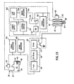
- Figure 13 is a schematic view showing an electronic timing circuit which releases the solenoid after a predetermined time interval upon an attempt to open the door and shows emergency condition detection circuitry for de-energizing the solenoid upon the occurrence of an emergency situation whereby the emergency exit door can open immediately.
- Figure 14 is a side view showing a second embodiment (which is preferred) of a keeper mounting arrangement and keeper guide in accordance with the instant invention.
- Figure 15 is a front view of the keeper shown in Figure 14.
- Figure 16 is a front view of the guide shown in Figure 14.
- Figures 17A and 17B are circuit diagrams showing the details of a now-preferred embodiment of the circuitry shown in Figure 13.
- Figures 18A and 18B are circuit diagrams of a circuit having many of the components of Figures 17A and 17B but used to control a plurality of doors.
- Figure 19 is a planar view of a control panel for a plurality of doors.
- Figure 20 is a top view of a circuit board mounting the various components shown in Figures 17A, 17B, 18A and 18B.
- Referring now to Figure 1, there is shown an
emergency exit door 20 which is hinged to close against adoor jamb 21 of adoor frame 22. Thedoor 20 is equipped with aconventional panic latch 23, which is unlatched by aconventional panic bar 24. A delay apparatus, designated generally by the numeral 25, is secured to thedoor frame 22 in an upper corner thereof adjacent the free edge of thedoor 20. When thedoor 20 is opened, it pivots about its hinged edge so as to move away from thedelay apparatus 25. While thedelay apparatus 25 is shown mounted in the corner of thedoor frame 22, it could be mounted at any convenient location, such as near the middle of the top frame member or along the vertical jamb so as to engage the free edge of the door. - Referring now to Figures 2 through 12 in general, there is shown a housing, designated generally by the numeral 26, which defines a
base 27 and includes aslot 28 through which thestrike portion 29 of a keeper, designated generally by the numeral 30, is passed in order to lock the door. - Preferably, the
housing 26 is mounted on thedoor frame 22, and thekeeper 30 is mounted on thedoor 20, so as to hold thedoor 20 against the door jamb 21 (also see Figure 1). - The strike portion of the
keeper 29 includes arecess 31 and astrike 32 which cooperate with a bolt, designated generally by the numeral 33. Thebolt 33 is a closure-operated swinging bolt which is pivoted on apivot 34 that is secured to thebase 27 of thehousing 26. The bot includes atooth 35 which projects into therecess 31 and anarm 37 on which is mounted amagnet 38 which cooperates with a Hall-Effect switch 39 to indicate when an attempt is made to open the door. Moreover, the arm 37.is engaged by thestrike 32 upon closing the door to rotate the bolt to its latched position (as will be fully explained hereinafter). - The
bolt 33 is dogged in the position shown in Figure 3 (also Figures 8 and 12) by a delay mechanism, which delay mechanism includes a hydraulic cylinder, designated generally by the numeral 41, and a solenoid, designated generally by the numeral 42, which solenoid is controlled by the circuitry of Figure 13, as will be explained hereinafter. Thehydraulic cylinder 41 is connected to thesolenoid 42 through adouble toggle linkage 43. As will be explained hereinafter,solenoid 42 either jams thetoggle linkage 43, as shown in Figures 3, 4, and 8 through 10, or breaks the toggle linkage, as is shown in Figures 5, 6 and 7. - As has been briefly explained in the "Background of the Invention", the instant invention utilizes a redundant delay system which includes throttling of the fluid in the
hydraulic cylinder 41 and/or a timed release effected by de-energizing thesolenoid 42. Preferably, the system will operate by de-energizing thesolenoid 42, but if for some reason the electrical system fails and the solenoid is not de-energized, then a fluid is throttled in thehydraulic cylinder 41, and the door can still be opened after a period of time. - As has been amply explained in the related patent applications, the
door 20 will release immediately upon an interruption of power to thesolenoid 42. This interruption is caused by either an expiration of a time interval set by the circuit in Figure 13 or the occurrence of an emergency condition detected by the circuit of Figure 13. Either of these conditions allow the solenoid to permit collapse thetoggle linkage 43. - Considering the
latch delay mechanism 25 in more detail, thebolt 33 has an elongatedslot 44 therein which receives apin 45 of aclevis 46. Theclevis 46 is rigidly attached to apiston rod 47 that, in turn, is secured to apiston 48 within thehydraulic cylinder 41. Ordinarily, thepiston 48 is held in the position of Figures 3-8 by fluid on thebottom side 49 of the piston. Thehydraulic cylinder 41 does not include a spring to project thepiston rod 47 out of the cylinder. All flow of hydraulic fluid is contained within thecylinder 41. - The
cylinder 41 is pivoted by apin 51 to a first toggle link, designated by the numeral 52, of thedouble toggle linkage 43. Thetoggle link 52 includes afirst link 53, which is pivoted by apin 54 to thebase 27, and asecond link 56, also pivoted onpin 51. Thelink 56 forms a second toggle link, designated generally by the numeral 57, with athird link 58, which is pivoted to link 56 by apin 60 at one end and to thebase 27 by apin 61 at the other end. - The
second toggle link 57 is controlled by anactuator rod 63, which is pivotably mounted on thepin 60 at one end and pivoted at the other end by apivot pin 66 to anarmature 67 of thesolenoid 42. Thearmature 67 is, in turn, positioned by either thecoil 68 of thesolenoid 42 or by aspring 69 which is overcome by applying current to thecoil 68, so as to lock-up the armature in the coil. - Referring now to Figures 3 through 12 which show a complete cycle of the system upon using the
solenoid 42 to release the system, when thedoor 20 is pushed in the direction of arrow 70 (see Figure 4) thestriker 29 of thekeeper 30 moves to the right, which causessurface 71 on therecess 31 the striker to engage thetooth 35 and to rotate thebolt 33 in the direction of arrow 72. Theelongated slot 44 in thebolt 33 drops down until the top end of the elongated slot hits thepin 45 onclevis 46, whereupon motion of thebolt 33 is arrested because hydraulic fluid in thehydraulic cylinder 41 becomes pressured. - When the
bolt 33 has rotated from the Figure 3 to the Figure 4 position, themagnet 38 on thearm 37 is moved to operate the Hall-Effect switch 39. This starts the timing circuitry of Figure 13. Preferably, the timing circuitry does not start its count for perhaps three to five seconds, so that only serious attempts to open the door will be recognized. The timing circuit runs for perhaps fifteen to thirty seconds, depending on its setting. In accordance with one embodiment of the inventor while the timing circuitry is running, the door can be returned from the Figure 4 position to the Figure 3 position, and the timing circuitry will continue to count. In accordance with another embodiment, the count stops when one releases pressure on the door. In any event, while the circuitry is counting, an alarm is ringing either over thedoor frame 22 or at a remote location (or both) indicating that someone is trying to open the door. - After the count is finished, the timing circuitry cuts power to the
coil 68, and thearmature 67 moves from the Figure 4 position to the Figure 5 position under the bias of thecoil spring 69. This causes theactuator rod 63 to push thesecond toggle link 57 overcenter from the straight position of Figure 4 to the collapsable position of Figure 5. Until thetoggle linkage 57 has been pushed overcenter, any force on thebolt 33 due to pulling by thesurface 71 onstriker 29 on thetooth 35 is transmitted by thepiston rod 47 and thehydraulic cylinder 41 to thetoggle linkage 52, tending to collapse thetoggle linkage 52 downwardly. This, of course, forces theactuator rod 63 upward and jams thearmature 67 against astop 75. However, once thelinkage 57 is pushed overcenter, as is illustrated in Figure 5, motion by thedoor 20 in the direction ofarrow 70 causes thestriker 29 to collapse thetoggle linkage 57. Thelatch bolt 33 and first and second toggle links 52 and 57, which make up thedouble toggle linkage 43, then move to the Figure 6 position in which thestriker 29 is released and thedoor 20 opens. As will be explained further hereinafter and in accordance with one embodiment of the invention, power to thecoil 68 remains off for perhaps ten seconds or so, so that thedoor 20 can continually open and shut for ten seconds after it has been initially opened. - If an emergency situation occurs, then current to the
coil 68 is interrupted, and thearmature 67 is urged by thespring 69 to the position of Figure 5, while thebolt 33 remains in the position of Figure 3. Thereafter, when thedoor 20 is pushed so as to open the door, thebolt 33 will move continuously from the Figure 3 position through the positions of Figures 4 and 5 to the position of Figure 6, so as to allow thedoor 20 to open immediately. - Upon closing the
door 20 by moving the door in the direction ofarrow 77, thestrike 32 on thestriker 29 hits thearm 37 and rotates thearm 37 from the Figure 6 position to the Figure 7 position. However, as is readily seen, Figure 7 is similar to Figure 5, with the exception that thebolt 33 is pushed back against thestop 37a.Spring 69 keeps thearmature 67 projected from thecoil 68 until the ten-second interval for holding the delay apparatus unlatched expires. Upon expiration of the ten-second interval, thecoil 68 is energized which draws thearmature 67 into the coil against the bias ofspring 69. This pulls thesecond toggle link 57 straight and holds thelink 57 straight due to engagement between thearmature 67 and stop 75 (see Fig. 8). Figure 8 is similar in configuration to Figure 3. - A second Hall-
Effect switch 80 is positioned adjacent to thesolenoid 42 and detects the position of thearmature 67. When thearmature 67 is drawn up into thecoil 68, then.the Hall-Effect switch 80 closes indicating, by appropriate means, that thedoor 20 is now locked. - While it is preferable that the system operate by cutting power to the
coil 68, it is conceivable that the timers might fail. It is also conceivable that the emergency interruption of power to thecoil 68 of thesolenoid 42 might not occur. As is seen in Figures 9 and 10, one can still open thedoor 20 by applying pressure thereto in the direction of thearrow 70. - As is seen in Figure 9, if the
solenoid 42 is energized, thesecond toggle linkage 57 cannot collapse. Accordingly, force applied by thesurface 71 on thetooth 35 of thebolt 33 is transmitted by thepiston rod 47 to thepiston 48. Thepiston 48 is equipped with a one-way valve 82 consisting of an 0-ring 83 which seals between thepiston 48 and thehydraulic cylinder 41 when urged upwardly by fluid pressure. As is seen in Figure 11, thevalve 82 opens when pushed downwardly by fluid pressure. This is due to the configuration ofsurface 85 on the side of thepiston 48 and is a well known conventional structure for a one-way valve within a hydraulic cylinder. - Considering Figure 9 specifically, the
piston 48 moves downwardly in the direction ofarrow 87 which forces the hydraulic fluid in thehydraulic cylinder 41 through asmall orifice 89 in thepiston 48 which throttles the fluid. Since theorifice 89 is small, it takes a considerable amount of time, perhaps fifteen to thirty seconds depending on the size of the orifice, to move enough fluid from thefirst side 49 of thepiston 48 to thesecond side 91 of the piston to allow thebolt 33 to move from the Figure 9 position to the Figure 10 position. During this time (because of a malfunction womewhere in the system), thesolenoid 42 has remained energized. However, as is seen in Figure 10, thedoor 20 has opened anyway even though the electronics of Figure 13 have failed. - Upon closing the
door 20 by moving the door in the direction ofarrow 95 in Figure 11, thestrike surface 32 on thestriker 29 ofkeeper 30 hits thearm 37 on thebolt 33 and rotates the bolt in the counterclockwise direction. This pulls thepiston 48 back up from the Figure 10 position toward the position of Figure 12. As is seen in Figure 11, while this is happening, the one-way valve 82 allows the fluid to flow fromside 91 ofpiston 48 around the outside of the piston to the space in the hydraulic cylinder adjacent to theside 49 of the piston. Thebolt 33 is then returned to its locked position, as is seen in Figure 12 (which is the same as Figures 3 and 8). - Referring now to Figure 13, where as preferred arrangement for the control of the
solenoid 42 is shown, thecoil 68 of the solenoid is connected at one end to an emergencysituation control circuit 100 and at the other end to atiming circuit 101. When energized, the coil retains thelatch 25 in the latched mode by drawing thearmature 67 up into the solenoid, as is seen in Figures 3, 8 and 12. Theemergency situation circuit 101 includes a power supply 102, and optionally a central station control panel 103 (which preferably includes switches for de-energizing the solenoid remotely), fire boxes 104, andsmoke detectors 105. These elements are connected in series with adropout relay 106, which includes amanual reset switch 107. If either the fire boxes 104 or thesmoke detector 105 indicate an emergency condition, thedropout relay 106 will be opened to cut off power from the power supply 102 to thecoil 68 of thesolenoid 42. Accordingly, thedoor 20 will open immediately if an emergency condition is sensed or if, for any reason, power to thesolenoid 42 is interrupted. - The
manual reset switch 107, which can be located at thecentral station 103, must be operated in order to reclose thedropout relay 106. If an emergency condition persists, then themanual reset 107 cannot resetdropout relay 106. Avisual indicator 108, in the form of a light, is provided at thecentral station 103 and perhaps adjacent to thedoor 20, so as to indicate whether the door is operating in an emergency mode or a delay mode. Thecoil 68 of thesolenoid 42 is attached to ground through the emitter of atransistor 110 located intiming circuit 101. Normally, thetransistor 110 is switched on so as to conduct power from power supply 102 to ground. However, when thetransistor 110 is switched off, thecoil 68 of thesolenoid 42 is no longer energized because it is in effect released by thetransistor allowing armature 67 to be urged outwardly by thespring 69. - The
timing circuitry 101 includes a three to five-second timer 115, which is preferably set at three seconds; a fifteen to thirty-second timer 116, which is preferably factory set; and a ten-second timer 117, which is triggered by thetimer 116 to turn offtransistor 110 for a period of ten seconds. The timers operate in series and are connected to the Hall-Effect switch 39 positioned adjacent to thebolt 33 so as to be activated upon movement of themagnet 38 in juxta-position with the Hall-Effect switch 39. Moreover, the Hall-Effect switch 39 is in series with the Hall-Effect switch 80 which detects the position ofarmature 67 in thesolenoid 42. - Upon pushing the
door 20 toward the open position, thebolt 33 is cammed from the Figure 3 to the Figure 4 position by thestriker 29, whereupon the Hall-Effect switch 39 operates which starts the three-second timer 115 and which also lights visual indicators 125 which may be at thecentral station 103 or perhaps at thedoor 20. The Hall-Effect switch 39 also energizes an audio indicator oralarm 126 located adjacent to thedoor 20, so as to indicate to the person trying to open the door and others in the vicinity that the door has been tampered with. Upon operating the Hall-Effect switch 39, thefirst timer 115 is started and counts the time interval with a duration of three to five seconds. - If the door is released before the three to five-second interval expires, then the
timer 115 is reset and will start all over again if the door is thereafter pushed. If the door is continually pressed for the three to five seconds, then thefirst timer 115 triggers thesecond timer 116 which runs for a period of fifteen to thirty seconds, the period being determined at the factory or during installation. In accordance with one embodiment of the invention, the timer l16 cannot be stopped or reset after being started. In other words, the operation is irreversable. Upon expiration of the time interval set by the timer 116 (preferably fifteen to thirty seconds), thesecond timer 116 generates a release signal which triggers thethird timer 117. Thethird timer 117 interrupts power to the base oftransistor 110 for an interval of ten seconds. While thetransistor 110 is turned off,solenoid 42 will be de-energized and thearmature 67 will project due to urging of thespring 69, thereby allowing the door to open immediately. - The
keeper 30 is made of spring steel and is secured to thedoor 20 byshoulder bolts 150. Thesholder bolts 150 are received inapertures 151 in anextended arm 153 of thekeeper 30. Theapertures 151 are larger thanshoulders 154 on theshoulder bolts 150 so that the keeper is self-adjusting. Preferably, theshoulder bolts 150 hold thearm 153 in frictional engagement with the surface of thedoor 20. Since thearm 153 is resilient, it will absorb forces applied to the door tending to open the door so as to act as a shock absorber and protect the lock mechanism in thehousing 26. - Figures 14, 15 and 16 disclose a keeper, designated generally by the numeral 160, and a keeper guide, designated generally by the numeral 161, which guides the keeper into the
housing 26. As is seen in Figures 15 and 16, thekeeper 160 is L-shaped having a mountingshank 163 and astrike portion 164. The mountingshank 163 is retained by first and second brackets, designated generally bynumerals bracket 165 includes a base plate 167 and aclamp plate 168 which fits over the base plate 167 and restrains theshank 163 midway between the ends of the shank. Both the base plate 167 andclamp plate 168 are held in place byscrews 171 which pass through the clamp, through the base plate and into thedoor 20. - The
bracket 166 includes abase portion 172 and a stepped clampingportion 173. The stepped clampingportion 173 has afirst flange 174 that has aslot 175 therein, which slot receives a pin 176. As is seen in Figure 16, the pin 176 is substantially smaller in cross-section than the width or height of theslot 175 so as to accommodate limited motion of the mountingshank 163. The stepped clampingportion 173 also has ascrew flange portion 178 which is joined to theflange 174 bystep 179. Thescrew flange 178 is secured over the base 172 by ascrew 180 which passes through thescrew flange 178, through thebase 172 and into thedoor 20. - Since there is play between the
shank 163 and the first andsecond brackets keeper 160 is free to move not only longitudinally in the direction ofarrow 181 but also laterally in the direction ofarrow 182. Accordingly, thekeeper 160 can adjust itself with respect to the latch bolt 33 (see Figures 2-12) inside of thecase 26. - In order to properly guide the
projection portion 164 of thekeeper 160, the case is equipped with aguide 161. Theguide 161 is positioned within anopening 182 through sidewall 183 of thecasing 26. Theguide 161 is'secured to wall 183 by a pair of mountingscrews 184 and has anopening 185 therethrough which is surrounded by top and bottombeveled walls beveled side walls beveled walls bottom wall 187 beyond thewall 186 in order to define aslot 191, which slot accommodates theshank portion 163 of thekeeper 160. - When the
door 20 is shut, the beveled walls 186-189 cam thekeeper portion 164 of thekeeper 160 into theopening 185 so that thekeeper 160 will align with thebolt 33 inside the housing 26 (see also Figures 2-11). The play provided by the loose mounting arrangement between thebrackets shank 163 allows the position of thekeeper 160 to be adjusted by the beveled surfaces 185-189 so that the keeper will be properly aligned. - Figures 17A, 17B, 18A, 18B, 19 and 20 disclose details of one embodiment that the block diagram circuitry of Figures 13 and 14 may assume and includes departures in design and function from what is disclosed in Figures 13 and 14.
- Referring now to Figures 17A and 17B, wherein a single door control system is disclosed, a
transformer 300 converts regular 60-cycle, 220/240 volt line current to 14 volt, 0.25 amp, 60-cycle current. The 60 hertz output fromtransformer 300 is applied overline 301 to connector TB1 through a three-ampere fuse 303 and is applied overline 302 to abridge rectifier 304, which bridge rectifier converts the AC supply current to DC. AnMOV 305 is connected across thebridge rectifier 304 to prevent voltage surges in excess of 56 volts peak-to-peak.from passing through into the rest of the circuitry by blowing thefuse 303 upon the occurrence of such a surge. The DC output frombridge rectifier 304 is applied overline 308 where it is filtered by a capacitor Cl to a voltage regulator 311 that controls the input voltage to the logic circuitry. Resistors R9 and R8 serve as voltage dividers which set the voltage output from regulator 311 at a specific voltage level suitable for the logic circuitry. Capacitors C2 and C3 further filter the output from voltage regulator 311. - The 60-cycle AC signal on
line 301 is applied to inputpins 10 of a ten-second counter IC1 and a twelve-bit counter IC2 in order to provide these counters with a driving pulse. - Before describing the logic circuitry components in detail, it is necessary to briefly describe the inputs from the lock itself, which is designated generally by the numeral 320. In accordance with the preferred embodiment, the output of the Hall-
Effect switch 39 overline 321 goes low upon moving the magnet 38 (preferably a rare earth magnet) relative to the Hall-Effect switch upon closing the door. The low online 321 applies a low to bothpins pin 3 out overline 322. The high onpin 3 also applies a high to pin 11 of 12-bit counter IC2 which locks the 12-bit counter IC2 in a reset mode. The output overline 322 is also applied to pin 4 of flip-flop IC5-A and to pin 9 of inverting AND gate IC4-B which results in a high onoutput pin 10 of the gate IC4-B, the output of which is applied overline 334 to pin 11 of a 10-second counter IC1. The high online 334 holds the 10-second counter IC1 in a reset mode. - When the
magnet 38 is moved or repositioned with respect to the Hall-Effect switch 39 upon opening the door, a high signal is applied topins line 322, which low is applied to pin 11 of 12-bit counter IC2 and starts the count. Counter IC2 is programmed for initiating the start of the 3-second nuisance time interval or the 15 or 30-second time delay before allowing thebolt 33 to be released by ,solenoid 42 (also see Figures 3-13). - The AC signal from the
transformer 300 applied overline 301 is applied to pin 10 of the ten-second counter IC1. The signal online 301 is a 60- hertz signal which the ten-second counter IC1 divides. The ten-second counter IC1 will count 675 cycles before resetting. Normally, in order to provide an output at three seconds, 180 cycles would be counted, but since there are only three gates available, 180 cycles is the maximum resolution and therefore the output occurs at 2.97 seconds instead of three seconds. At 2.97 seconds, pins 3, 2 and 13 of twelve-bit counter IC2 provide an output to AND gate IC3-A, which gives a high output frompin 6 which is applied overline 341 to pin 3 of flip-flop IC5A (Fig. 17B). - Flip-flop IC5A then provides a high output on
pin 1 which is applied through a 10K resistor R3 to transistor Ql. The emitter of transistor Ql applies a voltage overline 344 to a door horn 346 (physically located at the door 20) viajunction 1 of abus 347. Accordingly, thehorn 346 which is equivalent an aural indicator of Figure 13, sounds if the door is pressed against for three seconds, so as to displace themagnet 38 with respect to the Hall-Effect switch 39 for a period of three seconds. - The three-second delay before sounding the
horn 346 allows the system to discriminate between a serious attempt to open the emergency exit door and a nuisance. The signal applied to pin 10 of ten-second counter IC1 and pin 10 of twelve-bit counter IC2 continues the count in IC2 for generating an output onpins solenoid 42 to release thebolt 33 and allow the door to open. If a 30-second delay is desired, rather than a 15-second delay, then pin 15 of IC2 is connected to AND gate IC3B. - The release signal from AND gate IC3-B is transmitted to de-energize
solenoid 42 by placing a high on thepin 10 which is transmitted over theline 355 to pin 11 of flip-flop IC5-B. The output onpin 10 of flip-flop IC5B is applied overline 358 to turn on transistor Q3, which in turn switches off a power transistor Q2 that is connected to thesolenoid 42 byline 360. When power is cut to thesolenoid 42 by turning off power transistor Q2, the solenoid allows the toggle linkage holding thebolt 33 in a projected position to collapse so that the door will open. - When the door is shut after being opened, the
magnet 38 is again aligned with Hall-Effect switch 39. This causes a low output by the Hall-Effect switch 39 to be applied overline 321, and this low is applied topins pin 3 on AND gate IC4-A to go high, putting a high online 322, which high is applied to pin 11 of twleve-bit counter IC2 to reset IC2. In addition, the high online 322 is applied to pin 4 of flip-flop IC5-A in order to reset the flip-flop. Moreover, the high online 322 is applied to pin 9 of AND gate IC4-B, which also has a high on pin 8 due to a signal from AND gate IC4-C which has been pulsed by a low frompin 12 of flip-flop IC5-B. - The low on
output pin 10 of AND gate IC4-B is applied overline 334 to pin 11 of ten-second counter IC1, which low releases the ten-second counter from theAC line 301 applied to pin 10 of the 10-second counter. The input signal onpin 11 of ten-second counter IC1 causes the counter to begin counting a 10-second time period. When the 10-second time period is detected bypins line 367 to pin 10 of the flip-flop IC5B to reset the flip-flop. When the flip-flop IC5B is reset, pin 13 will go low and transistor Q3 will go low to turn on power transistor Q2. When power transistor Q2 is turned on, current will pass throughline 360 and energize thesolenoid 42 so as to relock the door. - In addition, as pin 13 of flip-flop IC5-B goes low, a low is applied to pin 6 of flip-flop IC5A, which is in the set condition, while a high is applied to pin 4 of flip-flop IC5A from
line 322, which is a reset. At this point, the flip-flop IC5Aresets causing pin 1 to go low and apply a low overline 370 to the base of transistor Ql, switching the transistor off and cutting current to line 344 which turns off thehorn 346. - If the door is shut and the lock is closed, and one wishes to check the system out, the central alarm or
smoke detector 105 has contacts 105-A therein which, when opened, causes anoptical transistor 372 to have a low output onpin 4 which applies a low topins 12 and 13 of AND gate IC4-D (Fig. 17B). This causes AND gate IC4-D to have a high output onpin 11, which high output is applied overline 378 to pin 8 of flip-flop IC5-B to set the flip-flop. Upon setting the flip-flop IC5-B, pin 13 goes high and a high is applied to trans- sistor Q3 and to pin 6 of flip-flop IC5-A. This in turn causespin 1 of flip-flop IC5-A to go high and turn on transistor Ql. - When Ql is turned on, the horn or
alarm 346 is energized and sounded. Since pin 13 of IC5B is high, transistor Q3 is turned on which grounds power transistor Q2 thereby turning off power transistor Q2 and releasingsolenoid 42 by cutting current toline 360. Consequently, thesolenoid 42 collapses thelinkage 57 allowing thebolt 33 to open upon pressure being placed against thedoor 20 so as to pullkeeper 29 from thebolt 33. - In addition, as pin 13 goes low, a low is applied to pin 6 of flip-flop IC5-A, which is in the set condition, while a high is applied to pin 4 of flip-flop IC5-A from
line 322, which is a reset. At this point, the flip-flop ICS-Aresets causing pin 1 to go low and apply a low overline 370 to the base of transistor Ql, switching the transistor off and cutting current to line 344 which turns off thehorn 346. - In order to facilitate testing or to compensate for false alarms, as soon as the contacts 105-A in the
smoke detector 105 close, a low is placed on line 371 connected to pin 2 of the optical transistor 372 (Fig. 17B) which causes theinfrared diode 372A in the transistor to glow turning on the transistor. This places a high onpin 4 of the transistor and a high onpins 12 and 13 of AND gate IC4-D. Pin 11 of AND gate IC4 then goes low applying a low signal overline 378 to pin 8 of flip-flop IC5-B which sets the flip-flop. When the flip-flop IC5-B is set, thehorn 346 ceases sounding and thesolenoid 42 is re-energized.Pin 12 of the flip-flop IC5-B was low so that thepins 5 and 6 of AND gate IC4-C, by virtue of having a low thereon, produce a high atpin 4 of AND gate IC4-C and input pin 8 of AND gate IC4-B. - The high at pin 9 of AND gate IC4-B is already high due to the lock being in its original reset condition which causes a low on
output pin 10 of AND gate IC4-B, which low is applied overline 334 to pin 11 of ten-second counter IC1 so as to release the ten-second counter.Pins line 367 that resets flip-flop IC5-B throughpin 10 of the flip-flop. As explained before, when flip-flop IC5-B is reset, thehorn 346 is turned on and thesolenoid 42 is de-energized allowing the door to open. This is the end of the cycle. - When the circuit is initially energized, it often takes 10 seconds to lock the
lock 25 and put the circuit in a functioning mode. The system goes into automatic reset upon power failure or upon initial starting of the system. This reset mode has a 10- second time interval. - If the door 20 (see Figures 1-12) is pushed and held for more than three seconds, the Hall-
Effect switch 39 goes high putting a high onpins output pin 3 to go high, placing a high onlines 322 so as to release the twelve-bit counter IC2 causing a count to be entered from outside the clocking source. When three seconds is decoded by the ten-second counter IC1, thehorn 346 will sound. - If the door is released before the time delay of 15 or 30 seconds, whichever is selected, the Hall-
Effect switch 39 will apply a low topins A causing pin 3 to go high. Whenpin 3 goes high, a high is applied toline 322 which places a high onreset pin 11 of twelve-bit counter IC2. The count then ceases which, as explained before, cuts power to thehorn 346 and resets the entire system. Consequently, nuisance situations are minimized by configuring the circuitry so that it responds only to a real effort to open the door. If one simply hits the bar,, thehorn 346 does not sound and the count does not start. The count starts only after a three-second interval. In accordance with this embodiment, if one releases the door after the three-second interval, then the count must start again. - Referring now more specifically to Figures 18A and 18B which discloses circuitry for a multiple door arrangement, the basic operation is essentially the same as with the circuit of Figures 17A and 17B. With the arrangement of Figures 18A and 18B, a plurality of doors 20 (eight are shown) are controlled by a single master control panel such as that shown in Figure 19. As is seen in Figure 19, the master control panel includes a plurality of
sections 401a-401n (four of which are shown) and apower section 410. The power section includes a light 411, an on-off switch 412 indicating whether or not the power is on or off, a fire alarm indicator light .413 and aspeaker 414 which gives an audible alarm at the central station when an attempt is being made to open one of the doors in the array. - Each of the
sections 401a-401n includes an on-off switch 420, ayellow LED 421, agreen LED 422 and ared LED 423. Thegreen LED 422 monitors the current to thesolenoid 42 and remains lit as long as the solenoid is energized. Accordingly, the condition of the door can be monitored from the central station. - As is seen in Figure 18A (which shows the circuitry for a single door), the
green lamp 422 is inserted inline 360 between thesolenoid 42 and power resistor Q2. When there is insufficient current flowing from the power transistor Q2 to thesolenoid 42, thegreen lamp 422 will not be lit indicating that there is a problem at the door. The yellow trigger light LED 421 (Figure 18A) becomes lit when someone has pressed the door for a period greater than three seconds. Theyellow trigger light 421 is connected to the emitter of transistor Ql and sounds at the same time that thehorn 414 sounds, indicating that an attempt at egress is occurring. While theyellow trigger light 421 is lit and thehorn 414 at the console is sounding, thehorn 346 at the door also sounds notifying people in the vicinity of the door and the person trying to open the door that an attempt to open the door is occurring. When the door finally opens, thered LED 423 lights concurrently with lighting ofyellow LED 421 and sounding of thehorns - When a fire alarm has been sounded to release all of the doors in the bank of doors, the light 413 in the
power section 410 is turned on. If it is desired to release all of the doors simultaneously, amaster switch 430 in the power section is thrown which extinguishes the green light ofLED 411. In addition aswitch 432 is associated with eachindividual section 401a-401n for releasing the doors individually. - In the multiple door system of Figures 18A and 18B, a clock circuit,' designated generally by the numeral 435, is connected by a
line 436 to pin 10 of IC2. Theclock circuit 435 utilizes a semiconductor chip 437 (MM 5369) that has a square wave 60-Hz output which is applied instead of the 60-Hz input overline 301 utilized when just a single door is being secured with the system. - The input voltage to the power section is controlled by an
input circuit 440 which changes a 24-volt DC input fromjacks 443 to 12 volts which is applied to various points in the circuit of Figures 18A and 18B. In the embodiment disclosed, a7812c terminal regulator 441 provides the 12-volt output at 1.5 amps. A 1000microfared capacitor 442 is used to filter out irregular line current. By utilizing the input regulator, 12 volts can be supplied with a variation of approximately 10%. - Referring now to Figure 20, the following components are mounted on each circuit board to contrust the circuitry of Figures 17A and 17B and to an extent Figure 18A.

- With respect to the single door system disclosed in Figures 17A and 17B in conjunction with the structure of Figures 1-16, the following sequence of events occurs:

- With respect to the multiple door system of Figures 18A, 18B and 19 in conjunction with the structure of Figures 1-16, the following sequence of events occurs:


- The aforedescribed examples and embodiments are illustrative of various forms that the invention may assume, and the invention is limited only by the following claims.
- It will be understood that Whilst the above discussion in relation to a particular form of the emergency exit door securing system has been particularly discussed in relation to a displaceable bolt form of door latching the principles of the invention could be used with electomagnetic arrangements in which the latching effects are obtained by the establishment of a magnetic force between means on the door member and the frame member for the purposes of locking and the removal of such magnetic force when it is desired to release the door member from the frame member.
Claims (25)
Priority Applications (1)
| Application Number | Priority Date | Filing Date | Title |
|---|---|---|---|
| AT82302457T ATE26734T1 (en) | 1981-05-15 | 1982-05-14 | DEVICE CONTROLLING THE OPENING MOMENT FOR SECURED EMERGENCY EXIT DOORS. |
Applications Claiming Priority (2)
| Application Number | Priority Date | Filing Date | Title |
|---|---|---|---|
| US263955 | 1981-05-15 | ||
| US06/263,955 US4470625A (en) | 1980-05-09 | 1981-05-15 | Emergency exit door latch with hydraulic and electronic delay |
Publications (3)
| Publication Number | Publication Date |
|---|---|
| EP0065418A2 true EP0065418A2 (en) | 1982-11-24 |
| EP0065418A3 EP0065418A3 (en) | 1983-01-26 |
| EP0065418B1 EP0065418B1 (en) | 1987-04-22 |
Family
ID=23003958
Family Applications (1)
| Application Number | Title | Priority Date | Filing Date |
|---|---|---|---|
| EP82302457A Expired EP0065418B1 (en) | 1981-05-15 | 1982-05-14 | Point-of-egress control device for safely securing emergency exit doors |
Country Status (4)
| Country | Link |
|---|---|
| US (1) | US4470625A (en) |
| EP (1) | EP0065418B1 (en) |
| AT (1) | ATE26734T1 (en) |
| DE (1) | DE3276126D1 (en) |
Cited By (9)
| Publication number | Priority date | Publication date | Assignee | Title |
|---|---|---|---|---|
| US4613176A (en) * | 1983-06-29 | 1986-09-23 | Reliable Security Systems, Inc. | Door latch mechanism |
| US4652862A (en) * | 1984-03-06 | 1987-03-24 | Constructions Electroniques de la Ferte Sous Jouarre | Surveillance and control system for emergency exists installed in a building |
| FR2591645A1 (en) * | 1985-12-12 | 1987-06-19 | Ferte Sous Jouarre Const Elect | Mechanism for opening and closing emergency exits |
| US4801163A (en) * | 1986-09-02 | 1989-01-31 | Emhart Industries Inc. | Exit device actuator and dogger |
| US4803482A (en) * | 1986-02-19 | 1989-02-07 | Alain Verslycken | Exit control and surveillance system |
| FR2658856A1 (en) * | 1990-02-23 | 1991-08-30 | Von Duprin Inc | DOOR OPENING DELAY DEVICE. |
| FR2662735A1 (en) * | 1990-06-05 | 1991-12-06 | Mecanismes Electro Realises In | LOCKING DEVICE FOR EMERGENCY EXIT. |
| CN107476675A (en) * | 2011-08-23 | 2017-12-15 | 冯·杜普林有限责任公司 | Outlet device component |
| US10584912B2 (en) | 2013-01-18 | 2020-03-10 | Triteq Lock And Security, Llc | Cooler lock |
Families Citing this family (31)
| Publication number | Priority date | Publication date | Assignee | Title |
|---|---|---|---|---|
| SE438523B (en) * | 1981-10-19 | 1985-04-22 | Stendals El Ab | LOAD FOR ROOF EXPORTS OR LIKE |
| US4573720A (en) * | 1983-09-01 | 1986-03-04 | Nicolai J Steven | Failsafe security lock |
| DE3512387A1 (en) * | 1985-02-12 | 1986-08-14 | Büro Patent AG, Glarus | Conveying installation with self-propelled rail-borne conveying trolleys |
| US4703962A (en) * | 1985-02-12 | 1987-11-03 | Reliable Security Systems, Inc. | Magnetic door lock with time delay option |
| GB8528445D0 (en) * | 1985-11-19 | 1985-12-24 | Taylor A M | Door locks |
| DE3716021A1 (en) * | 1987-05-14 | 1988-11-24 | Dorma Gmbh & Co Kg | Locking device for emergency-exit doors |
| US4904005A (en) * | 1988-11-18 | 1990-02-27 | Harrow Products, Inc. | Entrance security system |
| US5067757A (en) * | 1989-08-02 | 1991-11-26 | Von Duprin, Inc. | Panic exit device having noise suppression |
| US5076625A (en) * | 1989-09-14 | 1991-12-31 | Oxley Randall C | Electric strike |
| US5082316A (en) * | 1989-12-01 | 1992-01-21 | The Cookson Company | Release mechanism and method with alarm circuit |
| DE19928194B4 (en) * | 1999-06-19 | 2005-06-30 | Hörauf & Kohler Verwaltungs KG | Movement damper assembly with integrated key switch especially for motor vehicles |
| US20030000149A1 (en) * | 2001-02-23 | 2003-01-02 | Oakley Robert L. | Linearly actuated locking device for transit vehicle door system |
| US6641183B2 (en) * | 2001-09-27 | 2003-11-04 | Jackson Corporation | Door latch device |
| US6886305B2 (en) * | 2002-01-03 | 2005-05-03 | Jeffrey H. Ward | Residential electric door strike and installation method |
| KR20020041368A (en) * | 2002-04-15 | 2002-06-01 | (주)베스트메탈라인 | Lock Equipment of Fire Door |
| US6863317B2 (en) * | 2003-03-27 | 2005-03-08 | General Motors Corporation | Latch assembly |
| US7632774B2 (en) * | 2006-03-30 | 2009-12-15 | Headwaters Technology Innovation, Llc | Method for manufacturing supported nanocatalysts having an acid-functionalized support |
| US7722096B2 (en) | 2006-04-05 | 2010-05-25 | Von Duprin, Inc. | Latchbolt for a door lock assembly |
| US7832777B2 (en) * | 2006-04-05 | 2010-11-16 | Von Duprin, Inc. | Door lock assembly |
| US7603882B2 (en) * | 2006-09-15 | 2009-10-20 | Anthony, Inc. | Electric door lock system for refrigerated display cases |
| US8205387B2 (en) | 2007-04-12 | 2012-06-26 | Stanley Black & Decker, Inc. | Delayed egress sliding door and method |
| DE102007035218A1 (en) * | 2007-07-25 | 2009-01-29 | Keba Ag | Electrically automated unlocking lock, especially for locker-like storage systems |
| GB2451634A (en) * | 2007-08-06 | 2009-02-11 | Isla Ann Mclean | Security device with tether and time alarm |
| TWI355576B (en) * | 2009-02-20 | 2012-01-01 | Quanta Comp Inc | Electronic device |
| DE102009020498B4 (en) * | 2009-05-08 | 2015-08-27 | Binder Gmbh | Device for opening a door of a climatic cabinet, an incubator, an environmental simulation chamber or a freezer or the like |
| US20120032455A1 (en) * | 2010-08-03 | 2012-02-09 | Thase Enterprise Co., Ltd. | Press bar mechanism |
| US20140319850A1 (en) * | 2013-03-15 | 2014-10-30 | Securitech Group, Inc. | Magnetic door lock assembly |
| JP6782528B2 (en) * | 2015-01-22 | 2020-11-11 | 理想科学工業株式会社 | Door switchgear |
| US9777755B2 (en) * | 2015-04-07 | 2017-10-03 | Advance Lifts, Inc. | Locking actuator with a collision detection system for a lift |
| CN110939326A (en) * | 2019-12-06 | 2020-03-31 | 徐州科睿安防科技有限公司 | Intelligent housekeeper type all-dimensional protection security door lock |
| AU2022202866A1 (en) * | 2021-05-03 | 2022-11-17 | Carefusion 303, Inc. | Dispensing cabinet with emergency release |
Citations (5)
| Publication number | Priority date | Publication date | Assignee | Title |
|---|---|---|---|---|
| DE2741556A1 (en) * | 1977-09-15 | 1979-03-29 | Ver Baubeschlag Gretsch Co | Lock for lift or motor vehicle door - has solenoid actuated bolt and manual unlocking mechanism normally at rest |
| US4257631A (en) * | 1979-06-25 | 1981-03-24 | Reliable Security Systems, Inc. | Magnetic emergency exit door lock with delayed opening |
| US4314722A (en) * | 1979-08-10 | 1982-02-09 | Reliable Security Systems, Inc. | Timing apparatus for delaying opening of doors |
| US4324425A (en) * | 1978-02-15 | 1982-04-13 | Logan Emanuel L | Point-of-egress control device for securing exit doors safely |
| US4328985A (en) * | 1979-08-10 | 1982-05-11 | Reliable Security Systems, Inc. | Timing apparatus for delaying opening of doors |
Family Cites Families (14)
| Publication number | Priority date | Publication date | Assignee | Title |
|---|---|---|---|---|
| DE7403756U (en) * | 1974-10-31 | Gretsch & Co Gmbh | Floor spring with hold-open device | |
| US2733918A (en) * | 1956-02-07 | fischer | ||
| US2588010A (en) * | 1948-11-26 | 1952-03-04 | Rice Engineering Corp | Door hinge and check |
| CH304335A (en) * | 1954-01-28 | 1955-01-15 | Ott Hans | Door lock. |
| US2851296A (en) * | 1954-02-01 | 1958-09-09 | August Kobeli | Door latching mechanism |
| US2881020A (en) * | 1955-05-31 | 1959-04-07 | Cornelis J M Kok | Door latch |
| DE1130325B (en) * | 1958-11-07 | 1962-05-24 | Ahrend Libra N V | Door lock |
| US3309125A (en) * | 1964-09-22 | 1967-03-14 | Neveling Herwig | Automatic door lock |
| US3383130A (en) * | 1965-12-22 | 1968-05-14 | Anthony F. De Avila | Anti-tamper device for panic-proof doors |
| US3435643A (en) * | 1966-03-21 | 1969-04-01 | Edward C Pollak | Emergency door lock having alarm means |
| US3583740A (en) * | 1968-08-22 | 1971-06-08 | Norris Industries | Exit device vertical rod collapsible latch bolt |
| US3677043A (en) * | 1970-12-07 | 1972-07-18 | Clifford B Cox | Remote control door lock |
| US3970339A (en) * | 1975-01-15 | 1976-07-20 | Detex Corporation | Double swinging latchbolt |
| US4006471A (en) * | 1975-01-31 | 1977-02-01 | Detex Corporation | Emergency exit lock system for doors |
-
1981
- 1981-05-15 US US06/263,955 patent/US4470625A/en not_active Expired - Fee Related
-
1982
- 1982-05-14 EP EP82302457A patent/EP0065418B1/en not_active Expired
- 1982-05-14 DE DE8282302457T patent/DE3276126D1/en not_active Expired
- 1982-05-14 AT AT82302457T patent/ATE26734T1/en not_active IP Right Cessation
Patent Citations (5)
| Publication number | Priority date | Publication date | Assignee | Title |
|---|---|---|---|---|
| DE2741556A1 (en) * | 1977-09-15 | 1979-03-29 | Ver Baubeschlag Gretsch Co | Lock for lift or motor vehicle door - has solenoid actuated bolt and manual unlocking mechanism normally at rest |
| US4324425A (en) * | 1978-02-15 | 1982-04-13 | Logan Emanuel L | Point-of-egress control device for securing exit doors safely |
| US4257631A (en) * | 1979-06-25 | 1981-03-24 | Reliable Security Systems, Inc. | Magnetic emergency exit door lock with delayed opening |
| US4314722A (en) * | 1979-08-10 | 1982-02-09 | Reliable Security Systems, Inc. | Timing apparatus for delaying opening of doors |
| US4328985A (en) * | 1979-08-10 | 1982-05-11 | Reliable Security Systems, Inc. | Timing apparatus for delaying opening of doors |
Cited By (14)
| Publication number | Priority date | Publication date | Assignee | Title |
|---|---|---|---|---|
| US4613176A (en) * | 1983-06-29 | 1986-09-23 | Reliable Security Systems, Inc. | Door latch mechanism |
| US4652862A (en) * | 1984-03-06 | 1987-03-24 | Constructions Electroniques de la Ferte Sous Jouarre | Surveillance and control system for emergency exists installed in a building |
| FR2591645A1 (en) * | 1985-12-12 | 1987-06-19 | Ferte Sous Jouarre Const Elect | Mechanism for opening and closing emergency exits |
| US4803482A (en) * | 1986-02-19 | 1989-02-07 | Alain Verslycken | Exit control and surveillance system |
| US4801163A (en) * | 1986-09-02 | 1989-01-31 | Emhart Industries Inc. | Exit device actuator and dogger |
| FR2658856A1 (en) * | 1990-02-23 | 1991-08-30 | Von Duprin Inc | DOOR OPENING DELAY DEVICE. |
| FR2662735A1 (en) * | 1990-06-05 | 1991-12-06 | Mecanismes Electro Realises In | LOCKING DEVICE FOR EMERGENCY EXIT. |
| EP0461013A1 (en) * | 1990-06-05 | 1991-12-11 | Icb La Securite | Locking device for emergency exit |
| CN107476675A (en) * | 2011-08-23 | 2017-12-15 | 冯·杜普林有限责任公司 | Outlet device component |
| CN107476675B (en) * | 2011-08-23 | 2020-04-28 | 施拉奇锁有限责任公司 | Outlet device assembly |
| US10648200B2 (en) | 2011-08-23 | 2020-05-12 | Schlage Lock Company Llc | Exit device assembly |
| US11629529B2 (en) | 2011-08-23 | 2023-04-18 | Schlage Lock Company Llc | Exit device assembly |
| US10584912B2 (en) | 2013-01-18 | 2020-03-10 | Triteq Lock And Security, Llc | Cooler lock |
| US10591201B2 (en) | 2013-01-18 | 2020-03-17 | Triteq Lock And Security, Llc | Cooler lock |
Also Published As
| Publication number | Publication date |
|---|---|
| ATE26734T1 (en) | 1987-05-15 |
| DE3276126D1 (en) | 1987-05-27 |
| EP0065418B1 (en) | 1987-04-22 |
| US4470625A (en) | 1984-09-11 |
| EP0065418A3 (en) | 1983-01-26 |
Similar Documents
| Publication | Publication Date | Title |
|---|---|---|
| EP0065418A2 (en) | Point-of-egress control device for safely securing emergency exit doors | |
| US4540208A (en) | Point-of-egress control device for safely securing emergency exit doors | |
| EP0033740B1 (en) | Timing apparatus for delaying opening of doors | |
| US6609738B1 (en) | Electromagnetic door lock system | |
| US5065136A (en) | Door security system | |
| US4652028A (en) | Magnetic emergency exit door lock with time delay | |
| US4257631A (en) | Magnetic emergency exit door lock with delayed opening | |
| US4720128A (en) | Magnetic emergency exit door lock with time delay | |
| US4703962A (en) | Magnetic door lock with time delay option | |
| US4324425A (en) | Point-of-egress control device for securing exit doors safely | |
| CA2732817C (en) | Delayed egress exit device | |
| US4354699A (en) | Apparatus for delaying opening of doors | |
| US3353383A (en) | Door locking means | |
| CA2036632C (en) | Door exit-delaying means | |
| US4314722A (en) | Timing apparatus for delaying opening of doors | |
| WO1996013770A1 (en) | Operating circuits for locking device | |
| GB1420935A (en) | Safety locking means for a door | |
| US4351552A (en) | Emergency exit door latching and locking apparatus | |
| US4225164A (en) | Automatic door and window locking system | |
| US20120167644A1 (en) | Delayed egress paddle alarm door lock | |
| WO1983001478A1 (en) | Lock | |
| US4621451A (en) | Actuating and locking mechanism for sliding door | |
| US4344647A (en) | Exterior operating arrangement for emergency exit doors with delayed opening feature | |
| US3921541A (en) | Remote controlled strong box assembly and latch therefor | |
| CN215485336U (en) | Locking device of escape push rod lock |
Legal Events
| Date | Code | Title | Description |
|---|---|---|---|
| PUAI | Public reference made under article 153(3) epc to a published international application that has entered the european phase |
Free format text: ORIGINAL CODE: 0009012 |
|
| PUAL | Search report despatched |
Free format text: ORIGINAL CODE: 0009013 |
|
| AK | Designated contracting states |
Designated state(s): AT BE CH DE FR GB IT LI LU NL SE |
|
| AK | Designated contracting states |
Designated state(s): AT BE CH DE FR GB IT LI LU NL SE |
|
| 17P | Request for examination filed |
Effective date: 19830718 |
|
| GRAA | (expected) grant |
Free format text: ORIGINAL CODE: 0009210 |
|
| AK | Designated contracting states |
Kind code of ref document: B1 Designated state(s): AT BE CH DE FR GB IT LI LU NL SE |
|
| PG25 | Lapsed in a contracting state [announced via postgrant information from national office to epo] |
Ref country code: NL Effective date: 19870422 Ref country code: LI Effective date: 19870422 Ref country code: IT Free format text: LAPSE BECAUSE OF FAILURE TO SUBMIT A TRANSLATION OF THE DESCRIPTION OR TO PAY THE FEE WITHIN THE PRESCRIBED TIME-LIMIT;WARNING: LAPSES OF ITALIAN PATENTS WITH EFFECTIVE DATE BEFORE 2007 MAY HAVE OCCURRED AT ANY TIME BEFORE 2007. THE CORRECT EFFECTIVE DATE MAY BE DIFFERENT FROM THE ONE RECORDED. Effective date: 19870422 Ref country code: FR Free format text: THE PATENT HAS BEEN ANNULLED BY A DECISION OF A NATIONAL AUTHORITY Effective date: 19870422 Ref country code: CH Effective date: 19870422 Ref country code: BE Effective date: 19870422 Ref country code: AT Effective date: 19870422 |
|
| REF | Corresponds to: |
Ref document number: 26734 Country of ref document: AT Date of ref document: 19870515 Kind code of ref document: T |
|
| PG25 | Lapsed in a contracting state [announced via postgrant information from national office to epo] |
Ref country code: SE Effective date: 19870430 |
|
| REF | Corresponds to: |
Ref document number: 3276126 Country of ref document: DE Date of ref document: 19870527 |
|
| PG25 | Lapsed in a contracting state [announced via postgrant information from national office to epo] |
Ref country code: LU Free format text: LAPSE BECAUSE OF NON-PAYMENT OF DUE FEES Effective date: 19870531 |
|
| REG | Reference to a national code |
Ref country code: CH Ref legal event code: PL |
|
| EN | Fr: translation not filed | ||
| NLV1 | Nl: lapsed or annulled due to failure to fulfill the requirements of art. 29p and 29m of the patents act | ||
| PG25 | Lapsed in a contracting state [announced via postgrant information from national office to epo] |
Ref country code: DE Effective date: 19880202 |
|
| PLBE | No opposition filed within time limit |
Free format text: ORIGINAL CODE: 0009261 |
|
| STAA | Information on the status of an ep patent application or granted ep patent |
Free format text: STATUS: NO OPPOSITION FILED WITHIN TIME LIMIT |
|
| GBPC | Gb: european patent ceased through non-payment of renewal fee | ||
| 26N | No opposition filed | ||
| PG25 | Lapsed in a contracting state [announced via postgrant information from national office to epo] |
Ref country code: GB Effective date: 19881121 |