EP0065177B1 - Pot pour répéteurs d'une ligne de transmission - Google Patents
Pot pour répéteurs d'une ligne de transmission Download PDFInfo
- Publication number
- EP0065177B1 EP0065177B1 EP82103806A EP82103806A EP0065177B1 EP 0065177 B1 EP0065177 B1 EP 0065177B1 EP 82103806 A EP82103806 A EP 82103806A EP 82103806 A EP82103806 A EP 82103806A EP 0065177 B1 EP0065177 B1 EP 0065177B1
- Authority
- EP
- European Patent Office
- Prior art keywords
- cable
- pot
- repeaters
- bowl
- pins
- Prior art date
- Legal status (The legal status is an assumption and is not a legal conclusion. Google has not performed a legal analysis and makes no representation as to the accuracy of the status listed.)
- Expired
Links
- 230000005540 biological transmission Effects 0.000 title claims description 4
- 239000002184 metal Substances 0.000 claims description 15
- 239000004020 conductor Substances 0.000 claims description 14
- 238000007789 sealing Methods 0.000 claims description 10
- 150000001875 compounds Chemical class 0.000 claims description 3
- 238000009413 insulation Methods 0.000 claims 1
- 210000002105 tongue Anatomy 0.000 claims 1
- 239000011324 bead Substances 0.000 description 4
- 210000004907 gland Anatomy 0.000 description 2
- 230000001681 protective effect Effects 0.000 description 2
- 238000003466 welding Methods 0.000 description 2
- 230000004888 barrier function Effects 0.000 description 1
- 210000003323 beak Anatomy 0.000 description 1
- 239000011521 glass Substances 0.000 description 1
- 230000003100 immobilizing effect Effects 0.000 description 1
- 210000000056 organ Anatomy 0.000 description 1
- 230000008520 organization Effects 0.000 description 1
- 238000005192 partition Methods 0.000 description 1
- 230000000149 penetrating effect Effects 0.000 description 1
- 230000002093 peripheral effect Effects 0.000 description 1
- 230000010287 polarization Effects 0.000 description 1
- 230000000284 resting effect Effects 0.000 description 1
Images


Classifications
-
- H—ELECTRICITY
- H02—GENERATION; CONVERSION OR DISTRIBUTION OF ELECTRIC POWER
- H02G—INSTALLATION OF ELECTRIC CABLES OR LINES, OR OF COMBINED OPTICAL AND ELECTRIC CABLES OR LINES
- H02G15/00—Cable fittings
- H02G15/02—Cable terminations
- H02G15/06—Cable terminating boxes, frames or other structures
- H02G15/076—Cable terminating boxes, frames or other structures for multi-conductor cables
Definitions
- a pot for repeaters of a transmission line consists of a sealed enclosure serving as housing for repeaters in individual housings and of a connection device ensuring the electrical connections through the sealed enclosure between the repeaters organs and the cables of the transmission line.
- pots for repeaters whose watertight enclosure consists of a tank with a hermetically sealed lid enclosing a frame with cells serving as individual housings for repeaters and whose connection device consists of a pigtail cable penetrating into the tank by a tube fitted with a cable gland and possibly embedded in pitch, and terminating inside the tank by conventional multi-pin connectors designed to receive by interlocking the sockets fixed on the individual repeater boxes, in their part emerging from the chassis.
- These pots require significant wiring in the factory, the mounting of conventional multi-pin connectors at the end of a telecommunication cable is not possible on site.
- pots for repeaters provided for possible wiring on site.
- These pots include a tank with hermetically sealed lid fixed on a connection box.
- the tank contains a chassis formed by a basket at the bottom of which are fixed rows of connectors on which the individual boxes of the repeaters are connected.
- the connection device consists of metal inserts mounted on glass beads fixed through a sealing barrier separating the connection box from the inside of the tank, of a wiring connecting the metal inserts to the connectors of backplane and a pigtail cable that enters the junction box through a cable gland system ensuring sealing and whose conductors terminate on the metal inserts.
- Document DE-B-1 044 207 also discloses a sealed connection box for the end of a multiconductor cable comprising a housing which is provided with a sealed lateral cable inlet and a hermetically closing cover which contains a insulating plate supporting connection terminals passing right through it.
- this connection box is totally unsuitable for housing repeater boxes for which it was not intended.
- the object of the present invention is to provide a pot for simplified wiring repeaters which can be made on site and which allows direct connection to the end of a cable.
- the insulating base of the backplane connector is used to support the individual repeater boxes. Its upper face has rows of cells which guide and position the individual boxes of the repeaters and at the bottom of which appear the upper ends of the metal pins which are connected to the boxes. Its underside has, between the rows of cells of the gutters provided for housing the ends of the cable conductors (8) during their paths between the arrival of the cable and the pins to which they end.
- the pot for repeaters according to the invention does not have any intermediate wiring and has the advantage of considerably reducing the number of cut-off points, welds or interconnections with other equipment, all with great ease of implementation.
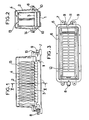
- Figures 1, 2 and 3 illustrate the general organization and layout of the various elements of a pot for repeaters according to the invention.
- the repeater pot has a shallow bowl 1 closed by a bell-shaped cover 2, and a backplane connector 3 to which the individual boxes 4 of the repeaters are fixed.
- the bowl 1 is of generally rectangular shape. It has a wide flat rim 5 in which a peripheral groove 6 is hollowed out housing a seal. It is fixed on its support by external tabs 7 arranged in the extension of its bottom on its short sides. Its side wall is pierced on one of its short sides with an inlet for line cable 8 with a sealing system detailed in FIG. 8 and on the other short side with two orifices 9 with tight sealing plugs provided for any pressurization valve and sockets for service cables used for auxiliary channels.
- the bowl 1 has on its internal side wall, along its long sides, horizontal benches 10, placed at mid-height, on which the backplane connector 3 rests. These benches 10 are connected, on the arrival side 9 for service cables, by a vertical partition 11 which divides the bottom of the bowl 1 into two compartments which can be filled separately with a compound to seal the cable ends.
- the backplane connector 3 is formed by a rectangular flat insulating base crossed by electrical connection pins.
- the insulating base occupies most of the interior surface of the bowl 1. It has on its upper face two rows of shallow cells 12, the dimensions of the bottoms of the individual repeater boxes 4.
- the individual repeater boxes 4 are placed upright on the backplane connector 3 their bottom embedded in the cells 12 and are held in place by poles 13 made of elastic metal wire, the ends of which hook into the insulating base on both sides. 'other of the cells 12.
- the connection pins which will be described later, pass through the base to the right of the cells 12 and end in the latter by pressure contacts intended to cooperate with pressure contacts which are placed facing each other. screws on the bottoms of the individual boxes 4 of the repeaters and on which are brought all the electrical connections of the repeaters with the outside.
- the cover 2 is bell-shaped with sufficient internal dimensions to encompass the volume occupied by the individual repeater boxes 4 disposed on the backplane connector 3. It has a flat rim 14, of the same outline as that of the bowl 1, which serves as a bearing surface for the seal and which is bordered by a drip pan 15.
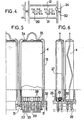
- FIGS. 4, 5 and 6 detail more particularly the shapes of the connection pins and of the insulating base of the backplane connector 3.
- connection pins 20 of the backplane connector 3 are made from a cut and folded metal strip. They terminate at the bottom of a cell 12 by a middle tab 21 folded at a right angle and on the underside of the insulating base by two legs 22, 23 forming a fork and serving as a self-stripping connection.
- connection pins 20 are eight in number per cell 12 distributed in two rows parallel to the length of the cell on either side of a center line with their tabs 21 folded down on this line median. They form with each cell 12 a rectangular connector with eight aligned flat contacts.
- a keying pin 24 disposed at the edge of each cell defines a single direction of introduction for the connector thus formed.
- the insulating base has a ribbed structure ensuring good resistance for a low weight. These ribs are formed on the one hand, on its upper face, by the edges 25 which delimit the cells 12 and are used for guiding and positioning the individual repeater boxes 4 and on the other hand, on its lower face, by beads 26 which coincide with the rows of connection pins 20 of the cells 12 and in which the slots serving as housing for the latter are formed.
- FIGS. 5 and 6 also detail the shape of the individual boxes 4 of repeaters, of their connector and of their retaining bar 13.
- An individual repeater unit 4 is in the form of a parallelepipedic cassette of small thickness whose height and width correspond to the dimensions of the printed circuit board 27 to which the components of the repeater are wired. All the electrical connections of a repeater with the outside are brought back on eight parallel conductive tracks 28 at the end of its printed circuit board 27 facing the bottom of its case. These eight parallel conductive tracks 28 have the same spacing as the eight aligned flat contacts of a cell 12 of the backplane connector 3-to which they can be connected by means of a connector with elastic contacts fixed to the bottom of the individual housing 4.
- This connector consists of an insulating strip 29 carrying eight elastic contacts 30.
- the insulating strip 29 has eight transverse grooves having the same spacing as res tracks conductive 28 or that the flat contacts of a cell 12 and serving as a housing for the eight elastic contacts 30. It is fixed to the end of the printed circuit board 27 and accessible by an opening in the bottom of the individual housing 4.
- the contacts elastic bands 30 are formed from metal strips folded in several sections according to an arc of a circle, a first panel projecting with respect to one of the faces of the insulating strip 29 resting on a conductive track 28 of the printed circuit board 27 while another section also projecting but oriented at a right angle parallel to the bottom of the individual housing 4 comes opposite a flat contact of a cell 12.
- a notch formed at one end of the insulating strip 29 cooperates with the lug 24 of a cell 12 to ensure polarization.
- the pressure between the elastic contacts 30 carried by the bottom of an individual housing 4 of the repeater and the flat contacts of a cell 12 is provided by a holding hoop 13 which delivers a pressure of at least 100 grams per contact and which immobilizes the individual housing 4 on the backplane 3.
- This retaining arch 13 is made of folded metal wire. It ends with hook beaks 31 which grip under the edges of openings 32 formed in the insulating base on either side of the cells 12. Its uprights make a slight zigzag giving it elasticity. It forms at its apex a gripping loop bordered by two counter-curves 33, 34 which snap between bosses carried by the front face of the individual repeater housings 4.
- FIG. 7 shows the small number of connections that a connection comprises between a conductor 40 of the cable 8 (FIG. 8) of the line and a conductive track 28 of a printed circuit board 27 to which the components of a repeater are wired .
- This connection in fact only comprises a pin 20 connected by a solderless connection to the end of the conductor 40 and an elastic contact 30 in pressure contact with the middle tab 21 of the pin 20 and with the conductive track 28, this which makes it particularly weak.
- FIG. 8 details the arrival of the cable 8 in the bowl 1 and its sealing system.
- the cable 8 is a multi-conductor cable with a metal casing 41 covered with a protective sheath 42.
- the passage of the cable 8 in the bowl 1 has a diameter greater than the cable 8 which allows a length of cable to be pulled through the cuvette during wiring of the backplane connector 3.
- the cable 8 is stripped of its protective sheath 42 and threaded into a crossing piece which seals the passage of the cable 8 through the wall of the bowl 1 and which is formed by a sleeve 43 and a nut 44.
- the sleeve 43 is metallic with an internal diameter adapted to that of the metallic casing 41 of the cable to which it is welded.
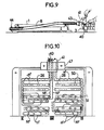
- Figure 9 illustrates the positions of the cable 8, the bowl 1 and the backplane connector 3 when wiring the latter on site.
- the cable 8 is drawn through the nut 44 of the crossing piece and through its passage through the bowl 1.
- the end of the cable 8 is prepared with its metal casing 41 released to allow mounting and welding of the sleeve 43 of the crossing piece.
- the end of the cable is then fixed in the cable clamp 47 of the backplane connector 3 which, turned over, offers perfect accessibility for wiring.
Landscapes
- Connector Housings Or Holding Contact Members (AREA)
- Details Of Connecting Devices For Male And Female Coupling (AREA)
- Coupling Device And Connection With Printed Circuit (AREA)
Applications Claiming Priority (2)
| Application Number | Priority Date | Filing Date | Title |
|---|---|---|---|
| FR8109072A FR2505568A1 (fr) | 1981-05-07 | 1981-05-07 | Pot pour repeteurs d'une ligne de transmission |
| FR8109072 | 1981-05-07 |
Publications (2)
| Publication Number | Publication Date |
|---|---|
| EP0065177A1 EP0065177A1 (fr) | 1982-11-24 |
| EP0065177B1 true EP0065177B1 (fr) | 1985-05-02 |
Family
ID=9258167
Family Applications (1)
| Application Number | Title | Priority Date | Filing Date |
|---|---|---|---|
| EP82103806A Expired EP0065177B1 (fr) | 1981-05-07 | 1982-05-04 | Pot pour répéteurs d'une ligne de transmission |
Country Status (5)
| Country | Link |
|---|---|
| US (1) | US4465899A (enExample) |
| EP (1) | EP0065177B1 (enExample) |
| CA (1) | CA1171484A (enExample) |
| DE (1) | DE3263359D1 (enExample) |
| FR (1) | FR2505568A1 (enExample) |
Families Citing this family (11)
| Publication number | Priority date | Publication date | Assignee | Title |
|---|---|---|---|---|
| FR2740936B1 (fr) * | 1995-11-02 | 1997-12-19 | Amblard Albert | Ensemble compose d'un chassis et d'un capot de protection |
| US20030026415A1 (en) * | 1997-11-06 | 2003-02-06 | Laetsch Erich K. | Methods and apparatus to improve thermal performance of 818/819 style repeater housings |
| US6292556B1 (en) | 1997-11-06 | 2001-09-18 | Anacapa Technology, Inc. | Local loop telecommunication repeater housings employing thermal collection, transfer and distribution via solid thermal conduction |
| US6310772B1 (en) * | 1999-09-02 | 2001-10-30 | Special Product Company | Enclosure for telecommunications equipment |
| US6430044B2 (en) | 2000-02-10 | 2002-08-06 | Special Product Company | Telecommunications enclosure with individual, separated card holders |
| US6404637B2 (en) | 2000-02-14 | 2002-06-11 | Special Product Company | Concentrical slot telecommunications equipment enclosure |
| US6514095B1 (en) | 2000-07-27 | 2003-02-04 | Special Product Company | Cable interface for electronic equipment enclosure |
| US6507494B1 (en) | 2000-07-27 | 2003-01-14 | Adc Telecommunications, Inc. | Electronic equipment enclosure |
| US6940014B1 (en) | 2000-07-27 | 2005-09-06 | Special Product Company | Modular electronic equipment enclosure comprising sealed cable interface module |
| US6625017B1 (en) | 2001-02-12 | 2003-09-23 | Special Products Company | Telecommunications enclosure with individual, separated card holders |
| US7031158B2 (en) * | 2002-10-30 | 2006-04-18 | Charles Industries, Ltd. | Heat pipe cooled electronics enclosure |
Family Cites Families (11)
| Publication number | Priority date | Publication date | Assignee | Title |
|---|---|---|---|---|
| DE7911860U1 (de) * | 1980-07-03 | Schiederwerk Guenter Schmidt Kg Fabrik Fuer Apparate Der Fernmelde- Und Elektrotechnik, 8500 Nuernberg | Fernmeldetechnischer vergießbarer und stufenweise erweiterbarer Kabelendverzweiger mit Überspannungsschutz | |
| US1956534A (en) * | 1929-10-23 | 1934-04-24 | Western Union Telegraph Co | Sealed terminal for insulated cables |
| DE1044207B (de) * | 1957-09-12 | 1958-11-20 | Quante & Co K G | Wettersicherer Fernmeldekabelendverzweiger |
| US3173732A (en) * | 1962-02-09 | 1965-03-16 | Brown Engineering Company Inc | Printed circuit board connector |
| US3671813A (en) * | 1970-12-10 | 1972-06-20 | Texas Instruments Inc | Panel board system and components thereof with connector and integrated circuit device |
| US3699396A (en) * | 1971-04-21 | 1972-10-17 | Honeywell Bull Soc Ind | Mounting system for printed circuit boards |
| JPS5544429B2 (enExample) * | 1973-05-11 | 1980-11-12 | ||
| DE2445381C2 (de) * | 1974-09-23 | 1976-11-04 | Krone Gmbh | Fernmeldekabel-endverschluss |
| FR2321794A1 (fr) * | 1975-08-05 | 1977-03-18 | Mars Actel | Tete de cable universelle |
| DE2814018C2 (de) * | 1978-03-31 | 1987-04-23 | Siemens AG, 1000 Berlin und 8000 München | Anschlußverteiler mit einer Vielzahl von den abisolierfreien Anschluß elektrischer Leiter gestattenden Klemmelementen |
| FR2440636A1 (fr) * | 1978-10-31 | 1980-05-30 | Nozick Jacques | Tete de cable avec protection pour repartiteur de central telephonique |
-
1981
- 1981-05-07 FR FR8109072A patent/FR2505568A1/fr active Granted
-
1982
- 1982-05-04 EP EP82103806A patent/EP0065177B1/fr not_active Expired
- 1982-05-04 DE DE8282103806T patent/DE3263359D1/de not_active Expired
- 1982-05-06 CA CA000402384A patent/CA1171484A/fr not_active Expired
- 1982-05-07 US US06/376,050 patent/US4465899A/en not_active Expired - Fee Related
Also Published As
| Publication number | Publication date |
|---|---|
| EP0065177A1 (fr) | 1982-11-24 |
| CA1171484A (fr) | 1984-07-24 |
| DE3263359D1 (en) | 1985-06-05 |
| FR2505568A1 (fr) | 1982-11-12 |
| FR2505568B1 (enExample) | 1983-07-08 |
| US4465899A (en) | 1984-08-14 |
Similar Documents
| Publication | Publication Date | Title |
|---|---|---|
| EP0065177B1 (fr) | Pot pour répéteurs d'une ligne de transmission | |
| EP0429036B1 (fr) | Boîtier métallique pour connecteur électrique | |
| EP0330525B1 (fr) | Canalisation électrique préfabriquée adaptable à plusieurs intensités nominales, du type comprenant un support plat rainuré d'isolation pour barres conductrices | |
| LU82054A1 (fr) | Assemblage de connecteur electrique | |
| EP0859526A1 (fr) | Panneau modulaire de brassage, pour réseaux de données | |
| FR2497411A1 (fr) | Connecteur electrique pour cable multiconducteur plat et son procede de fabrication | |
| FR2516313A1 (fr) | Ensemble de blindage pour connecteur electrique et procede de realisation d'une terminaison sur un cable totalement blinde | |
| FR2517476A1 (fr) | Systeme de raccordement electrique et element de connecteur | |
| CA1186388A (fr) | Module electronique enfichable dans un connecteur de bus | |
| FR2548468A1 (fr) | Systeme de branchement d'un cable plat | |
| FR2653607A1 (fr) | Dispositif pour la realisation d'ensembles pour la commande et la protection de circuits electriques basse tension. | |
| EP0768727B1 (fr) | Bornier électrique | |
| EP0098212A2 (fr) | Structure de blindage pour carte à circuits imprimés | |
| EP0392422A1 (fr) | Procédé de connexion dérivative et de piquage d'un cable électrique multifilaire blindé et connecteur pour la mise en oeuvre du procédé | |
| FR2579859A1 (fr) | Arrangement de modules de circuits electriques et bati comprenant un tel arrangement | |
| EP2383849B1 (fr) | Dispositif de raccordement électrique vertical | |
| EP0488099B1 (fr) | Boîtier de protection contre les perturbations électromagnétiques, pour dispositif de connexion électrique | |
| EP1422799A1 (fr) | Dispositif de distribution d'énergie pour appareillages électriques | |
| EP1146619B1 (fr) | Montant de châssis formant simultanément conduit de distribution et de répartition de l'énergie électrique | |
| FR2708385A1 (fr) | Bloc de jonction électrique. | |
| EP0478469A1 (fr) | Bornier de raccordement pour la distribution du neutre et de la terre dans un coffret électrique | |
| FR2618026A1 (fr) | Canalisation electrique prefabriquee pour la realisation de circuits de distribution electrique pouvant incorporer des zones de distribution commandables a conformations variables | |
| EP0522540B1 (fr) | Tête de câble à protection pour répartiteur téléphonique | |
| EP1039604A1 (fr) | Système de distribution d'énergie électrique dans les étages d'un immeuble | |
| EP0523552B1 (fr) | Tête de câble téléphonique |
Legal Events
| Date | Code | Title | Description |
|---|---|---|---|
| PUAI | Public reference made under article 153(3) epc to a published international application that has entered the european phase |
Free format text: ORIGINAL CODE: 0009012 |
|
| AK | Designated contracting states |
Designated state(s): BE DE FR GB IT LU NL |
|
| 17P | Request for examination filed |
Effective date: 19830505 |
|
| ITF | It: translation for a ep patent filed | ||
| GRAA | (expected) grant |
Free format text: ORIGINAL CODE: 0009210 |
|
| AK | Designated contracting states |
Designated state(s): BE DE FR GB IT LU NL |
|
| PG25 | Lapsed in a contracting state [announced via postgrant information from national office to epo] |
Ref country code: LU Free format text: LAPSE BECAUSE OF NON-PAYMENT OF DUE FEES Effective date: 19850531 |
|
| REF | Corresponds to: |
Ref document number: 3263359 Country of ref document: DE Date of ref document: 19850605 |
|
| PLBE | No opposition filed within time limit |
Free format text: ORIGINAL CODE: 0009261 |
|
| STAA | Information on the status of an ep patent application or granted ep patent |
Free format text: STATUS: NO OPPOSITION FILED WITHIN TIME LIMIT |
|
| 26N | No opposition filed | ||
| PGFP | Annual fee paid to national office [announced via postgrant information from national office to epo] |
Ref country code: NL Payment date: 19860531 Year of fee payment: 5 |
|
| BERE | Be: lapsed |
Owner name: CIE INDUSTRIELLE DES TELECOMMUNICATIONS CIT-ALCA Effective date: 19870531 |
|
| PG25 | Lapsed in a contracting state [announced via postgrant information from national office to epo] |
Ref country code: NL Effective date: 19871201 |
|
| NLV4 | Nl: lapsed or anulled due to non-payment of the annual fee | ||
| PG25 | Lapsed in a contracting state [announced via postgrant information from national office to epo] |
Ref country code: FR Free format text: LAPSE BECAUSE OF NON-PAYMENT OF DUE FEES Effective date: 19880129 |
|
| PG25 | Lapsed in a contracting state [announced via postgrant information from national office to epo] |
Ref country code: DE Effective date: 19880202 |
|
| GBPC | Gb: european patent ceased through non-payment of renewal fee | ||
| REG | Reference to a national code |
Ref country code: FR Ref legal event code: ST |
|
| PG25 | Lapsed in a contracting state [announced via postgrant information from national office to epo] |
Ref country code: GB Free format text: LAPSE BECAUSE OF NON-PAYMENT OF DUE FEES Effective date: 19881121 |
|
| PG25 | Lapsed in a contracting state [announced via postgrant information from national office to epo] |
Ref country code: BE Effective date: 19890531 |