EP0064852B1 - Freight-carrying platforms - Google Patents
Freight-carrying platforms Download PDFInfo
- Publication number
- EP0064852B1 EP0064852B1 EP82302253A EP82302253A EP0064852B1 EP 0064852 B1 EP0064852 B1 EP 0064852B1 EP 82302253 A EP82302253 A EP 82302253A EP 82302253 A EP82302253 A EP 82302253A EP 0064852 B1 EP0064852 B1 EP 0064852B1
- Authority
- EP
- European Patent Office
- Prior art keywords
- platform
- link
- aperture
- adjacent
- bolt
- Prior art date
- Legal status (The legal status is an assumption and is not a legal conclusion. Google has not performed a legal analysis and makes no representation as to the accuracy of the status listed.)
- Expired
Links
- 230000015572 biosynthetic process Effects 0.000 claims description 2
- 238000005755 formation reaction Methods 0.000 claims description 2
- 238000005266 casting Methods 0.000 description 13
- 238000010276 construction Methods 0.000 description 3
- 230000014759 maintenance of location Effects 0.000 description 1
- 238000004519 manufacturing process Methods 0.000 description 1
- 238000009877 rendering Methods 0.000 description 1
Images

Classifications
-
- B—PERFORMING OPERATIONS; TRANSPORTING
- B65—CONVEYING; PACKING; STORING; HANDLING THIN OR FILAMENTARY MATERIAL
- B65D—CONTAINERS FOR STORAGE OR TRANSPORT OF ARTICLES OR MATERIALS, e.g. BAGS, BARRELS, BOTTLES, BOXES, CANS, CARTONS, CRATES, DRUMS, JARS, TANKS, HOPPERS, FORWARDING CONTAINERS; ACCESSORIES, CLOSURES, OR FITTINGS THEREFOR; PACKAGING ELEMENTS; PACKAGES
- B65D90/00—Component parts, details or accessories for large containers
- B65D90/0006—Coupling devices between containers, e.g. ISO-containers
- B65D90/0013—Twist lock
-
- B—PERFORMING OPERATIONS; TRANSPORTING
- B65—CONVEYING; PACKING; STORING; HANDLING THIN OR FILAMENTARY MATERIAL
- B65D—CONTAINERS FOR STORAGE OR TRANSPORT OF ARTICLES OR MATERIALS, e.g. BAGS, BARRELS, BOTTLES, BOXES, CANS, CARTONS, CRATES, DRUMS, JARS, TANKS, HOPPERS, FORWARDING CONTAINERS; ACCESSORIES, CLOSURES, OR FITTINGS THEREFOR; PACKAGING ELEMENTS; PACKAGES
- B65D90/00—Component parts, details or accessories for large containers
- B65D90/0026—Corner fittings characterised by shape, configuration or number of openings
-
- B—PERFORMING OPERATIONS; TRANSPORTING
- B65—CONVEYING; PACKING; STORING; HANDLING THIN OR FILAMENTARY MATERIAL
- B65D—CONTAINERS FOR STORAGE OR TRANSPORT OF ARTICLES OR MATERIALS, e.g. BAGS, BARRELS, BOTTLES, BOXES, CANS, CARTONS, CRATES, DRUMS, JARS, TANKS, HOPPERS, FORWARDING CONTAINERS; ACCESSORIES, CLOSURES, OR FITTINGS THEREFOR; PACKAGING ELEMENTS; PACKAGES
- B65D2590/00—Component parts, details or accessories for large containers
- B65D2590/0008—Coupling device between containers
- B65D2590/0016—Lashings means
-
- Y—GENERAL TAGGING OF NEW TECHNOLOGICAL DEVELOPMENTS; GENERAL TAGGING OF CROSS-SECTIONAL TECHNOLOGIES SPANNING OVER SEVERAL SECTIONS OF THE IPC; TECHNICAL SUBJECTS COVERED BY FORMER USPC CROSS-REFERENCE ART COLLECTIONS [XRACs] AND DIGESTS
- Y10—TECHNICAL SUBJECTS COVERED BY FORMER USPC
- Y10T—TECHNICAL SUBJECTS COVERED BY FORMER US CLASSIFICATION
- Y10T24/00—Buckles, buttons, clasps, etc.
- Y10T24/28—Freight container to freight container fastener
Definitions
- the present invention relates to platforms which can be loaded with freight for transport thereof and which, when empty, can be stacked and connected together to enable them to be handled as a unit.
- the platform may be a simple flat, generally rectangular base or may be a folding or collapsible container consisting of a base and end frames or corner posts hinged to the base for movement between an erect position in which freight can be carried on the base and a collapsed position in which the end walls or frames or corner posts lie on top of the base to enable a plurality of such platforms to be stacked and linked together to form a unit.
- twistlocks are expensive to manufacture and project permanently from the upper surface of the platform thus rendering them liable to damage from lifting spreader equipment or another platform.
- each releasable connection means comprising a movable bolt and receiving member having an aperture so that the bolt of the platform engages the aperture of a receiving member of an adjacent platform to enable the platform and the said adjacent platform to be locked one relative to the other when assembled together in a stack, characterised in that each aperture receiving member is a link movable relative to the frame of the platform and is biassed to a retracted position in which it does not protrude from the top or bottom surface of the platform and is manually movable against the bias into an extended position in which a portion of the link projects proud of the platform, the bolt being engaged in the aperture of a corresponding link of an adjacent platform when the corresponding link is in its extended position.
- the link is in the form of a loop, such as a chain link, held captive on a bar secured to the platform structure, the dimensions of the opening through the loop being sufficient to permit movement between the retracted and projecting positions.
- the platform has registration means for engagement with an adjacent similar platfqrm in a stack to ensure that each platform remains correctly positioned in the stack.
- the registration means may comprise step formations or retractable elements engageable in apertures of an adjacent platform.
- the platform shown in Figures 1 to 4 of the drawings has a rectangular perimeter frame (Fig. 1) comprising two side members 1 of I-section and two end members 2 of channel-section. At their ends, the side members 1 and end members 2 are welded to corner structures consisting of a bottom corner casting 3 and an upper portion 4 in the form of a rectangular tube which is welded at its lower end to the top face of the casting 3 and at its upper end to a lifting plate 5 formed with an aperture 6 for engagement by lifting means conventionally used for lifting ISO containers.
- a load-carrying surface for the platform is formed in a conventional manner by planking 7 secured by screws 8 to cross-members 9 welded at each end to the side members 1. Freight on the platform may be secured into position by lashing to lashing bars 10 to which water-proof covers such as tarpaulins can also be secured.
- the platform may also be equipped with tubular tunnels (indicated at 11) to receive the tines of a fork-lift truck for transporting the platform, particularly when empty.
- Figures 2 to 4 show the arrangement adjacent to one corner of a platform for securing two adjacent platforms in a stack of such platforms to each other (in the empty condition of the platforms). This arrangement is repeated at each corner of the platform.
- a link 12 of the kind used to form a chain has two straight sides 12a interconnected by semicircular ends 12b forming a closed loop with an opening therethrough.
- the link 12 is rendered captive by a bar 13 which is welded at one end to the corner tube 4 and at its other end to a bracket plate 14 welded to the channel-section end member 2.
- the link 12 hangs down from the bar 13 as shown in Figures 3 and 4 and does not project above the load carrying surface 15.
- the top flange portions 16 above the chain link 12 are cut away to form a slot 17 through which the link can be swung or pushed upwards by hand to project above the surface 15.
- a gusset plate 18 is welded between the inner face of the end member 2 and the corner tube 4.
- the unloaded platform has been lifted, for example by means of a fork-lift truck or by means of a top lifting device engaged with the opening 6, and lowered onto the top of an identical, lower platform.
- the upper platform (and of course also the lower platform) has a bolt 19 slidable in aligned holes in the bracket 14 and a further bracket 20 welded to the end member 2.
- the bolt 19 carries an operating handle 21 formed with two apertures 22, 23 either of which can be engaged over a pin 24 fixed to the end member 2, the pin 24 carrying a captive fastener 25 movable between the upright locking position shown in Figures 3 and 4 and a horizontal position permitting the handle to be disengaged from the pin 24.
- the bolt 19 can be secured either in its locked position shown in Figure 3 or in an unlocked position in which the pin is engaged through the hole 23.
- the chain link 12' of the lower platform can be lifted or swung as indicated by the arrow A in Fig. 4 into its projecting position in which it extends through the notch 17' of the lower platform and a similar notch 26 in the lower flange of the end member 2 of the upper platform into a position in which the uppermost part of the opening of the lower link 12' is aligned with the bolt 19.
- the latter can then be moved (to the left) into the position shown in Fig. 3 in which the left-hand end of the bolt extends through the link 12' into a socket hole 27 drilled into the corner casting 3.
- the bolt 19 is then secured in this position by turning the bolt 19 by means of the handle until the latter is engaged by means of its hole 22 over the pin 24 for retention by the locking element 25.
- a stack of platforms when connected together at each corner in the manner described above can be lifted as a unit by lifting the uppermost platform. It can be seen from Figures 3 and 4 that the top surface of the lifting plates 5 is slightly below the load carrying surface of the platforms and that the bottom surface of the bottom corner castings 3 lies below the bottom surfaces of the side and end members 1 and 2. This arrangement provides a snug nesting fit and longitudinal location and registration of one platform relative to its neighbour or neighbours.
- This arrangement reduces or eliminates the application of longitudinal and transverse racking forces to the links, these racking forces being instead transferred directly from one platform to the next by their snug nesting engagement with each other.
- the platforms in a unit can be quickly separated by disengaging the catch elements 25, pulling the handle 21 clear of the pin 24 and then sliding the bolt 19 by means of the handle to disengage the bolt from the hole 27 and from the link 12'. The latter then drops down through the notches 26 and 17 into a retracted position in which its upper end rests on the bar 13' of the lower platform. The upper platform can then be lifted away by a fork-lift truck or other lifting device.
- the prop plate 35 is flush with the top surface 36 of the platform and with the top of the top flange of the perimeter beams of the platform. This enables the empty platform to be lifted by all existing prop-lifting spreader equipment. With this arrangement, the lateral location and registration between super-imposed platforms of the kind shown in Figures 1-4 is not available. Instead, this function is performed by retractable spigot members 40 which are located in at least two, diagonally opposed, corners of the platform.
- Each spigot member 40 is vertically movable in its corner between an upper position in which a spigot head portion 41 projects upwards through the aperture 6 for engagement in a corresponding aperture in the bottom corner casting 3 of a super- imposed platform, and a lower position in which the spigot member 40 is retracted and. rests on top of the bottom corner casting 3.
- the uppermost portion 42 of the head 41 of the spigot member 40 which in the extended position projects above the top plate 35 is of slightly reduced horizontal dimensions as compared with the lower portion 43 of the head 41 to facilitate entry of the uppermost portion 42 into the aperture in the super-imposed bottom corner casting 3.
- the spigot member 40 has a central cylindrical waist 44 of diameter slightly less than the width 45 ( Figure 5) of the top aperture 6 and the plate 35, and a bottom portion 47 of generally similar profile to the head 41 but projecting on one side 48 further than the head 41.
- each spigot member 40 has a central channel 52 extending for the full height of the spigot member, on one side, of width slightly greater than the width of the rib 49.
- the spigot member has lobe portions 53 and 54 respectively of the head 41 and bottom portion 47, these lobe portions both having a width slightly less than the distance between the ribs 50 and 51.
- the lower lobe 54 rests on top of the rib 49 while the projections formed by the part 48 on each side of the channel 52 rest on the tops of the ribs 50 and 51.
- the spigot member 40 can be moved from this position to a lower, retracted position in which a crane hook or twist lock of a lifting spreader can be engaged in the opening 6.
- the spigot member is lifted to bring its waist 44 into alignment with the top plate 35.
- the spigot member 40 can then be turned through 180° to bring the channel 52 into register with the rib 49 and the lobes 53 and 54 into register with the space between the ribs 50 and 51.
- the spigot member 40 can then be lowered to rest on the top face of the bottom corner casting 3, leaving the top aperture 6 unobstructed.
- it is formed with a central bore 55 having a chordal lip 56 extending across the top adjacent the channel 52.
- the greater radial extent of the part 48 of the bottom portion 47 engages the under side of the top plate 35 when the spigot member 40 is lifted and thereby prevents accidental removal of the spigot member through the top plate 35.
Landscapes
- Engineering & Computer Science (AREA)
- Mechanical Engineering (AREA)
- Pallets (AREA)
Description
- The present invention relates to platforms which can be loaded with freight for transport thereof and which, when empty, can be stacked and connected together to enable them to be handled as a unit. The platform may be a simple flat, generally rectangular base or may be a folding or collapsible container consisting of a base and end frames or corner posts hinged to the base for movement between an erect position in which freight can be carried on the base and a collapsed position in which the end walls or frames or corner posts lie on top of the base to enable a plurality of such platforms to be stacked and linked together to form a unit.
- It is known to provide such platforms with standard ISO castings at the corners thereof for engagement with twistlock devices of top lifting spreader equipment so that a platform can be lifted for stacking purposes for example. However, when stacking platforms the ISO castings thereon have been provided with twistlocks to ensure the platforms in the stack are secured one to the next. In practice the twistlocks are either left in the ISO castings by an operator and obstruct the entry therein of twistlocks permanently provided on the top lift spreader equipment or removable twistlocks are used which often become lost. Neither situation is satisfactory.
- An attempt to overcome these problems is to provide in addition to the twistlocks of the ISO corner casting additional twistlock constructions mounted inwardly of the platform corners so that when platforms are stacked one upon the other in their folded down position the additional twistlock engages an aperture in the next adjacent platform in the stack to interlock-the platforms. One such construction is disclosed in USA Patent No. 3664273. The pre-characterising portion of
claim 1 is based on the disclosure of this citation. - However, the additional twistlocks are expensive to manufacture and project permanently from the upper surface of the platform thus rendering them liable to damage from lifting spreader equipment or another platform.
- According to the present invention these problems can be overcome by providing a platform for carrying freight having a fixed frame with ISO connectors mounted in the frame and a plurality of releasable connection means mounted in the frame and distanced from the ISO corner units for connecting the platform to an adjacent platform in a stack, each releasable connection means comprising a movable bolt and receiving member having an aperture so that the bolt of the platform engages the aperture of a receiving member of an adjacent platform to enable the platform and the said adjacent platform to be locked one relative to the other when assembled together in a stack, characterised in that each aperture receiving member is a link movable relative to the frame of the platform and is biassed to a retracted position in which it does not protrude from the top or bottom surface of the platform and is manually movable against the bias into an extended position in which a portion of the link projects proud of the platform, the bolt being engaged in the aperture of a corresponding link of an adjacent platform when the corresponding link is in its extended position.
- Advantageously, the link is in the form of a loop, such as a chain link, held captive on a bar secured to the platform structure, the dimensions of the opening through the loop being sufficient to permit movement between the retracted and projecting positions.
- Preferably, the platform has registration means for engagement with an adjacent similar platfqrm in a stack to ensure that each platform remains correctly positioned in the stack. The registration means may comprise step formations or retractable elements engageable in apertures of an adjacent platform.
- Embodiments of the invention will now be described by way of example with reference to the accompanying drawings, in which:-
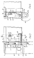
- Figure ,1 is a plan view of a goods carrying platform,
- Figure 2 shows one corner of the platform on an enlarged scale,
- Figure 3 is a vertical elevation view in the direction of the arrows III of Figure 2,
- Figure 4 is a vertical section on the line IV-IV of Figure 3,
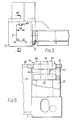
- Figure 5 is a view similar to Figure`2 but of a modified platform,
- Figure 6 is a view partly in elevation and partly in section on the line VI-VI of Figure 5, and
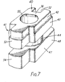
- Figure 7 is a perspective view of the retractable registration spigot shown in Figure 6.
- The platform shown in Figures 1 to 4 of the drawings has a rectangular perimeter frame (Fig. 1) comprising two
side members 1 of I-section and twoend members 2 of channel-section. At their ends, theside members 1 andend members 2 are welded to corner structures consisting of abottom corner casting 3 and anupper portion 4 in the form of a rectangular tube which is welded at its lower end to the top face of thecasting 3 and at its upper end to alifting plate 5 formed with anaperture 6 for engagement by lifting means conventionally used for lifting ISO containers. - A load-carrying surface for the platform is formed in a conventional manner by planking 7 secured by
screws 8 to cross-members 9 welded at each end to theside members 1. Freight on the platform may be secured into position by lashing to lashingbars 10 to which water-proof covers such as tarpaulins can also be secured. The platform may also be equipped with tubular tunnels (indicated at 11) to receive the tines of a fork-lift truck for transporting the platform, particularly when empty. - Figures 2 to 4 show the arrangement adjacent to one corner of a platform for securing two adjacent platforms in a stack of such platforms to each other (in the empty condition of the platforms). This arrangement is repeated at each corner of the platform.
- A
link 12 of the kind used to form a chain has twostraight sides 12a interconnected by semicircular ends 12b forming a closed loop with an opening therethrough. Thelink 12 is rendered captive by abar 13 which is welded at one end to thecorner tube 4 and at its other end to abracket plate 14 welded to the channel-section end member 2. - When no platform is superimposed on the platform, the
link 12 hangs down from thebar 13 as shown in Figures 3 and 4 and does not project above theload carrying surface 15. However, thetop flange portions 16 above thechain link 12 are cut away to form a slot 17 through which the link can be swung or pushed upwards by hand to project above thesurface 15. To compensate for the loss of thetop flange 16 at this point, agusset plate 18 is welded between the inner face of theend member 2 and thecorner tube 4. - As shown in Figures 3 and 4, the unloaded platform has been lifted, for example by means of a fork-lift truck or by means of a top lifting device engaged with the
opening 6, and lowered onto the top of an identical, lower platform. - To enable the two platforms to be connected together by means of the links 12' of the lower platform, the upper platform (and of course also the lower platform) has a
bolt 19 slidable in aligned holes in thebracket 14 and afurther bracket 20 welded to theend member 2. Thebolt 19 carries anoperating handle 21 formed with twoapertures pin 24 fixed to theend member 2, thepin 24 carrying acaptive fastener 25 movable between the upright locking position shown in Figures 3 and 4 and a horizontal position permitting the handle to be disengaged from thepin 24. With this arrangement, thebolt 19 can be secured either in its locked position shown in Figure 3 or in an unlocked position in which the pin is engaged through thehole 23. In the latter position, the chain link 12' of the lower platform can be lifted or swung as indicated by the arrow A in Fig. 4 into its projecting position in which it extends through the notch 17' of the lower platform and asimilar notch 26 in the lower flange of theend member 2 of the upper platform into a position in which the uppermost part of the opening of the lower link 12' is aligned with thebolt 19. The latter can then be moved (to the left) into the position shown in Fig. 3 in which the left-hand end of the bolt extends through the link 12' into asocket hole 27 drilled into thecorner casting 3. Thebolt 19 is then secured in this position by turning thebolt 19 by means of the handle until the latter is engaged by means of itshole 22 over thepin 24 for retention by thelocking element 25. - Thus, a stack of platforms when connected together at each corner in the manner described above, can be lifted as a unit by lifting the uppermost platform. It can be seen from Figures 3 and 4 that the top surface of the
lifting plates 5 is slightly below the load carrying surface of the platforms and that the bottom surface of thebottom corner castings 3 lies below the bottom surfaces of the side andend members - This arrangement reduces or eliminates the application of longitudinal and transverse racking forces to the links, these racking forces being instead transferred directly from one platform to the next by their snug nesting engagement with each other.
- When required for loading, the platforms in a unit can be quickly separated by disengaging the
catch elements 25, pulling thehandle 21 clear of thepin 24 and then sliding thebolt 19 by means of the handle to disengage the bolt from thehole 27 and from the link 12'. The latter then drops down through thenotches 26 and 17 into a retracted position in which its upper end rests on the bar 13' of the lower platform. The upper platform can then be lifted away by a fork-lift truck or other lifting device. - In the modified corner construction shown in Figures 5-7, the
prop plate 35 is flush with thetop surface 36 of the platform and with the top of the top flange of the perimeter beams of the platform. This enables the empty platform to be lifted by all existing prop-lifting spreader equipment. With this arrangement, the lateral location and registration between super-imposed platforms of the kind shown in Figures 1-4 is not available. Instead, this function is performed byretractable spigot members 40 which are located in at least two, diagonally opposed, corners of the platform. Eachspigot member 40 is vertically movable in its corner between an upper position in which aspigot head portion 41 projects upwards through theaperture 6 for engagement in a corresponding aperture in thebottom corner casting 3 of a super- imposed platform, and a lower position in which thespigot member 40 is retracted and. rests on top of thebottom corner casting 3. As can be seen in Figures 6 and 7, theuppermost portion 42 of thehead 41 of thespigot member 40 which in the extended position projects above thetop plate 35 is of slightly reduced horizontal dimensions as compared with thelower portion 43 of thehead 41 to facilitate entry of theuppermost portion 42 into the aperture in the super-imposedbottom corner casting 3. - Beneath the
head 41, thespigot member 40 has a centralcylindrical waist 44 of diameter slightly less than the width 45 (Figure 5) of thetop aperture 6 and theplate 35, and abottom portion 47 of generally similar profile to thehead 41 but projecting on oneside 48 further than thehead 41. - In its uppermost, projecting position, the
bottom portion 47 rests on the top surfaces of threevertical ribs bottom corner casting 3. Eachspigot member 40 has acentral channel 52 extending for the full height of the spigot member, on one side, of width slightly greater than the width of therib 49. At its opposite side, the spigot member haslobe portions head 41 andbottom portion 47, these lobe portions both having a width slightly less than the distance between theribs - In the upper, extended position shown in Figure 6, the
lower lobe 54 rests on top of therib 49 while the projections formed by thepart 48 on each side of thechannel 52 rest on the tops of theribs spigot member 40 can be moved from this position to a lower, retracted position in which a crane hook or twist lock of a lifting spreader can be engaged in theopening 6. For this purpose, the spigot member is lifted to bring itswaist 44 into alignment with thetop plate 35. Thespigot member 40 can then be turned through 180° to bring thechannel 52 into register with therib 49 and thelobes ribs spigot member 40 can then be lowered to rest on the top face of thebottom corner casting 3, leaving thetop aperture 6 unobstructed. To assist manipulation of thespigot member 40, it is formed with acentral bore 55 having achordal lip 56 extending across the top adjacent thechannel 52. The greater radial extent of thepart 48 of thebottom portion 47 engages the under side of thetop plate 35 when thespigot member 40 is lifted and thereby prevents accidental removal of the spigot member through thetop plate 35. - To move the spigot member from its lower retracted position to its upper projecting position, it is merely necessary to lift the spigot member again to the position in which the
waist 44 registers with thetop plate 35, turn the spigot member through 180° and then lower it to rest on the top faces of theribs
Claims (6)
Applications Claiming Priority (2)
| Application Number | Priority Date | Filing Date | Title |
|---|---|---|---|
| GB8113339 | 1981-04-30 | ||
| GB8113339 | 1981-04-30 |
Publications (2)
| Publication Number | Publication Date |
|---|---|
| EP0064852A1 EP0064852A1 (en) | 1982-11-17 |
| EP0064852B1 true EP0064852B1 (en) | 1986-07-23 |
Family
ID=10521500
Family Applications (1)
| Application Number | Title | Priority Date | Filing Date |
|---|---|---|---|
| EP82302253A Expired EP0064852B1 (en) | 1981-04-30 | 1982-04-30 | Freight-carrying platforms |
Country Status (3)
| Country | Link |
|---|---|
| US (1) | US4546945A (en) |
| EP (1) | EP0064852B1 (en) |
| DE (1) | DE3272113D1 (en) |
Families Citing this family (16)
| Publication number | Priority date | Publication date | Assignee | Title |
|---|---|---|---|---|
| PL264225A1 (en) * | 1986-02-21 | 1987-12-28 | Shipping container | |
| FR2616114B1 (en) * | 1987-06-03 | 1991-05-17 | Lohr Sa | BUILT-IN LOCKING BLOCK WITH BUILT-IN LOCK FOR LOAD CARRIER STRUCTURE |
| US5810186A (en) * | 1991-08-12 | 1998-09-22 | Lam; David Choon Sen | Goods transporting platform |
| GB9117420D0 (en) * | 1991-08-12 | 1991-09-25 | Lam David C S | Transporting goods |
| GB2263684A (en) * | 1992-02-03 | 1993-08-04 | Lin Pac Mouldings | Interlockable pallets. |
| US7057256B2 (en) | 2001-05-25 | 2006-06-06 | President & Fellows Of Harvard College | Silicon-based visible and near-infrared optoelectric devices |
| US7442629B2 (en) | 2004-09-24 | 2008-10-28 | President & Fellows Of Harvard College | Femtosecond laser-induced formation of submicrometer spikes on a semiconductor substrate |
| US6561739B1 (en) | 2001-10-25 | 2003-05-13 | The United States Of America As Represented By The Secretary Of The Navy | Load transporting modular platform system |
| DE102010007675B3 (en) * | 2010-02-10 | 2011-06-30 | Kapelski, Rainer, 24401 | slot gripper |
| US8692198B2 (en) | 2010-04-21 | 2014-04-08 | Sionyx, Inc. | Photosensitive imaging devices and associated methods |
| CN103081128B (en) | 2010-06-18 | 2016-11-02 | 西奥尼克斯公司 | High-speed photosensitive device and related method |
| AU2012100084B4 (en) * | 2011-02-02 | 2012-11-15 | Load And Move Pty Ltd | A Method of Handling a Container |
| US9496308B2 (en) | 2011-06-09 | 2016-11-15 | Sionyx, Llc | Process module for increasing the response of backside illuminated photosensitive imagers and associated methods |
| EP2732402A2 (en) | 2011-07-13 | 2014-05-21 | Sionyx, Inc. | Biometric imaging devices and associated methods |
| US9064764B2 (en) | 2012-03-22 | 2015-06-23 | Sionyx, Inc. | Pixel isolation elements, devices, and associated methods |
| US9209345B2 (en) | 2013-06-29 | 2015-12-08 | Sionyx, Inc. | Shallow trench textured regions and associated methods |
Family Cites Families (13)
| Publication number | Priority date | Publication date | Assignee | Title |
|---|---|---|---|---|
| US26873A (en) * | 1860-01-17 | crane | ||
| US922293A (en) * | 1908-01-11 | 1909-05-18 | River & Rail Transp Company | Freight-car. |
| US2488222A (en) * | 1946-08-31 | 1949-11-15 | American Seating Co | Combination desk and chair structure |
| US3107634A (en) * | 1960-02-29 | 1963-10-22 | Pullman Inc | Arrangement for transporting freight in containers on railroad cars having long travel cushioning characteristics |
| US3162320A (en) * | 1961-06-22 | 1964-12-22 | Highway Trailer Ind Inc | Body member connecting mechanism |
| USRE26873E (en) | 1968-05-07 | 1970-04-28 | Pallet locking mechanism | |
| GB1252000A (en) * | 1968-11-21 | 1971-11-03 | ||
| US3752511A (en) * | 1971-06-04 | 1973-08-14 | Line Fast Corp | Container coupler |
| DE2153499A1 (en) * | 1971-10-27 | 1973-05-03 | Fiala Kg Martin | STACKING PIN FOR LOCKING LOADING PALLETS ARRANGED ABOVE |
| GB1603801A (en) * | 1977-05-20 | 1981-12-02 | Howe D E | Freight carrier |
| SE409983B (en) * | 1978-01-20 | 1979-09-17 | Orsa Kaettingfabrik Ab | DEVICE AT A LINING BAR |
| DE2847704A1 (en) * | 1978-11-03 | 1980-05-14 | Mafi Transport Systeme Gmbh | FLAT WITH A PIVOTING BEARING CORNER SUPPORT |
| US4394101A (en) * | 1981-01-19 | 1983-07-19 | The United States Of America As Represented By The Secretary Of The Navy | Height adjustable cargo container locking mechanism |
-
1982
- 1982-04-29 US US06/373,304 patent/US4546945A/en not_active Expired - Fee Related
- 1982-04-30 EP EP82302253A patent/EP0064852B1/en not_active Expired
- 1982-04-30 DE DE8282302253T patent/DE3272113D1/en not_active Expired
Also Published As
| Publication number | Publication date |
|---|---|
| DE3272113D1 (en) | 1986-08-28 |
| EP0064852A1 (en) | 1982-11-17 |
| US4546945A (en) | 1985-10-15 |
Similar Documents
| Publication | Publication Date | Title |
|---|---|---|
| EP0064852B1 (en) | Freight-carrying platforms | |
| US3664273A (en) | Load carrying stacking platforms | |
| US4214669A (en) | Cargo container | |
| US4591307A (en) | Corner fitting with retractable twist lock | |
| US5275301A (en) | Collapsible freight container with gates | |
| US8529175B2 (en) | Method for transporting concentrated mass loads by container | |
| US5111950A (en) | Shipping container | |
| US7722101B2 (en) | Cargo shipping container spreader and method | |
| EP0029750B1 (en) | Folding containers | |
| US7905528B2 (en) | Spreader frame for cargo container | |
| US3557855A (en) | Pallet having hinged end panels and flexible cover members | |
| US20030198552A1 (en) | Freight container and lift casting therefore and method for lifting and transporting same | |
| US7011479B2 (en) | Shipping platform | |
| WO2007111618A1 (en) | Shipping and storage system | |
| US9045280B2 (en) | Collapsible storage container | |
| US4618068A (en) | Method and apparatus for shipping and storing cargo | |
| CN1368932A (en) | Freight container | |
| US3178216A (en) | Cargo pallet construction | |
| EP2036826A2 (en) | Pallet with collapsible frame and bag | |
| US5115933A (en) | Freight container | |
| EP0152290A2 (en) | Folding freight carriers | |
| US4349108A (en) | Containers | |
| WO1994000369A1 (en) | Lift fitting for cargo containers | |
| KR20040071315A (en) | Self-locking, self-adjusting receptacles, particularly containers | |
| EP1571096B1 (en) | A transport system |
Legal Events
| Date | Code | Title | Description |
|---|---|---|---|
| PUAI | Public reference made under article 153(3) epc to a published international application that has entered the european phase |
Free format text: ORIGINAL CODE: 0009012 |
|
| AK | Designated contracting states |
Designated state(s): DE FR GB IT |
|
| 17P | Request for examination filed |
Effective date: 19830308 |
|
| RAP1 | Party data changed (applicant data changed or rights of an application transferred) |
Owner name: SEA CONTAINERS LTD |
|
| GRAA | (expected) grant |
Free format text: ORIGINAL CODE: 0009210 |
|
| AK | Designated contracting states |
Kind code of ref document: B1 Designated state(s): DE FR GB IT |
|
| ITF | It: translation for a ep patent filed | ||
| REF | Corresponds to: |
Ref document number: 3272113 Country of ref document: DE Date of ref document: 19860828 |
|
| ET | Fr: translation filed | ||
| PLBE | No opposition filed within time limit |
Free format text: ORIGINAL CODE: 0009261 |
|
| STAA | Information on the status of an ep patent application or granted ep patent |
Free format text: STATUS: NO OPPOSITION FILED WITHIN TIME LIMIT |
|
| 26N | No opposition filed | ||
| ITTA | It: last paid annual fee | ||
| PGFP | Annual fee paid to national office [announced via postgrant information from national office to epo] |
Ref country code: FR Payment date: 19930317 Year of fee payment: 12 |
|
| PGFP | Annual fee paid to national office [announced via postgrant information from national office to epo] |
Ref country code: DE Payment date: 19930322 Year of fee payment: 12 |
|
| PGFP | Annual fee paid to national office [announced via postgrant information from national office to epo] |
Ref country code: GB Payment date: 19930329 Year of fee payment: 12 |
|
| PG25 | Lapsed in a contracting state [announced via postgrant information from national office to epo] |
Ref country code: GB Effective date: 19940430 |
|
| PG25 | Lapsed in a contracting state [announced via postgrant information from national office to epo] |
Ref country code: FR Effective date: 19941229 |
|
| PG25 | Lapsed in a contracting state [announced via postgrant information from national office to epo] |
Ref country code: DE Effective date: 19950103 |
|
| GBPC | Gb: european patent ceased through non-payment of renewal fee |
Effective date: 19940430 |
|
| REG | Reference to a national code |
Ref country code: FR Ref legal event code: ST |