EP0064591A1 - Sheet feed and registration method and system - Google Patents
Sheet feed and registration method and system Download PDFInfo
- Publication number
- EP0064591A1 EP0064591A1 EP82102507A EP82102507A EP0064591A1 EP 0064591 A1 EP0064591 A1 EP 0064591A1 EP 82102507 A EP82102507 A EP 82102507A EP 82102507 A EP82102507 A EP 82102507A EP 0064591 A1 EP0064591 A1 EP 0064591A1
- Authority
- EP
- European Patent Office
- Prior art keywords
- sheet
- platen
- sensor
- registration
- belt
- Prior art date
- Legal status (The legal status is an assumption and is not a legal conclusion. Google has not performed a legal analysis and makes no representation as to the accuracy of the status listed.)
- Granted
Links
- 238000000034 method Methods 0.000 title claims description 19
- 238000001514 detection method Methods 0.000 claims description 2
- 239000011521 glass Substances 0.000 description 29
- 239000004020 conductor Substances 0.000 description 20
- 230000032258 transport Effects 0.000 description 16
- 238000004364 calculation method Methods 0.000 description 5
- 238000010586 diagram Methods 0.000 description 4
- 230000002457 bidirectional effect Effects 0.000 description 3
- 238000005286 illumination Methods 0.000 description 2
- 230000003134 recirculating effect Effects 0.000 description 2
- 230000001143 conditioned effect Effects 0.000 description 1
- 230000000694 effects Effects 0.000 description 1
- 230000000977 initiatory effect Effects 0.000 description 1
Images


Classifications
-
- B—PERFORMING OPERATIONS; TRANSPORTING
- B65—CONVEYING; PACKING; STORING; HANDLING THIN OR FILAMENTARY MATERIAL
- B65H—HANDLING THIN OR FILAMENTARY MATERIAL, e.g. SHEETS, WEBS, CABLES
- B65H9/00—Registering, e.g. orientating, articles; Devices therefor
- B65H9/20—Assisting by photoelectric, sonic, or pneumatic indicators
-
- B—PERFORMING OPERATIONS; TRANSPORTING
- B65—CONVEYING; PACKING; STORING; HANDLING THIN OR FILAMENTARY MATERIAL
- B65H—HANDLING THIN OR FILAMENTARY MATERIAL, e.g. SHEETS, WEBS, CABLES
- B65H9/00—Registering, e.g. orientating, articles; Devices therefor
-
- G—PHYSICS
- G03—PHOTOGRAPHY; CINEMATOGRAPHY; ANALOGOUS TECHNIQUES USING WAVES OTHER THAN OPTICAL WAVES; ELECTROGRAPHY; HOLOGRAPHY
- G03B—APPARATUS OR ARRANGEMENTS FOR TAKING PHOTOGRAPHS OR FOR PROJECTING OR VIEWING THEM; APPARATUS OR ARRANGEMENTS EMPLOYING ANALOGOUS TECHNIQUES USING WAVES OTHER THAN OPTICAL WAVES; ACCESSORIES THEREFOR
- G03B27/00—Photographic printing apparatus
- G03B27/32—Projection printing apparatus, e.g. enlarger, copying camera
- G03B27/52—Details
- G03B27/62—Holders for the original
- G03B27/6207—Holders for the original in copying cameras
- G03B27/625—Apparatus which relate to the handling of originals, e.g. presence detectors, inverters
-
- Y—GENERAL TAGGING OF NEW TECHNOLOGICAL DEVELOPMENTS; GENERAL TAGGING OF CROSS-SECTIONAL TECHNOLOGIES SPANNING OVER SEVERAL SECTIONS OF THE IPC; TECHNICAL SUBJECTS COVERED BY FORMER USPC CROSS-REFERENCE ART COLLECTIONS [XRACs] AND DIGESTS
- Y10—TECHNICAL SUBJECTS COVERED BY FORMER USPC
- Y10S—TECHNICAL SUBJECTS COVERED BY FORMER USPC CROSS-REFERENCE ART COLLECTIONS [XRACs] AND DIGESTS
- Y10S271/00—Sheet feeding or delivering
- Y10S271/902—Reverse direction of sheet movement
Definitions
- the present invention relates to sheet feed and registration methods and systems.
- the present arrangement is of a similar type to the last mentioned prior art arrangement. However, it does not suffer from the disadvantage that a sheet is precisely aligned at the point beyond the platen. Instead, all that is required is that the sheet passes this point. Thus sheet feed velocity can be considerably increased. Furthermore, instead of reversing the sheet a short, fixed distance, the reversal is performed over a calculated distance, which can, therefore, be varied to accomodate various sheet sizes and various registration positions.
- the present invention provides a sheet feed and registration system including a platen upon which a sheet is to be registered, sheet feed means for feeding a sheet to, and over, the platen, and drive means for driving the sheet feed means bidirectionally, characterised by a sheet sensor positioned in the path of sheet feed away from the platen and control means coupled to the drive means and sheet sensor, said control means being operative, in response to signals from the sensor indicating that a sheet has passed over the platen in one direction over the sensor position and then passed from the sensor position back towards the platen in the opposite direction, to control movement of the sheet in said opposite direction from the sensor position to a calculated registration position on the platen.
- the invention further provides a method of feeding and registering a sheet on a platen characterised by the steps of feeding the sheet over the platen in one direction to a position past a point beyond the platen and thereafter reversing the feed to return the sheet to a registration position on the platen at a calculated distance from said point.
- FIG. 1 shows a copier/duplicator system embodying an electronic registration paper gate.
- the copier/duplicator system is fitted with an exposure platen 12.
- the exposure platen 12 is transparent and has a forward registration position 14 and a rear registration position 44.
- a document to be copied is positioned on the glass so that the leading edge of the document is in alignment with glass registration position 14.
- the document is then illuminated by the illumination system of the copier (not shown).
- the illumination system of the copier not shown
- a latent or electrostatic image of the original document is formed on the photoconductive surface (not shown) of the copy.
- the electrostatic image is then transported to a plurality of processing stations where it is toned or developed and transferred to a supporting media. Sll og these components and/or processing stations are well known, and therefore, are not shown in the drawings nor will be described in detail.
- a recirculating automatic document feeder ( R AD F ) 16 is mounted to the frame of the copier/duplicator 10.
- the RADF is usually fitted with a support tray in which original documents to be copied are loaded.
- a document 18 to be copied is removed from the tray and is delivered by transport means 20 to the transport section of RADF 16. It is then transported across the platen by a vacuum transport belt entrained over rollers 24 and 26.
- Drive roller 24 is coupled to the shaft of a bidirectional servo-controlled belt motor 28.
- the belt can be transported bidirectionally in the directions identified by arrows 34 and 36, respectively to position a document at any registration zone on the surface of the exposure platen 12.
- a direction/position sensor 38 in the form of a two-phase tachometer is coupled to the shaft of the DC motor.
- the tachometer output pulses on conductors 40 and 42 are processed by a servo-control system 30.
- the servo-control system generates signals on conductor 32 which are coupled to DC motor 28 to form a closed-loop servo system.
- a glass reference sensor (GRS) 46 is disposed off the exposure platen 12.
- the sensor is mounted so that a document, which is transported by the vacuum transport belt past the glass reference position 14 to a point beyond the sensor, can be sensed.
- the sensor provides a signal on conductor 48.
- This signal is applied to the servo-control system means 30 to initiate an algorithm which drives the DC bidirectional motor so that the vacuum transport belt with an attached document can be positioned at registration position 14, 44 or any other selected registration position on the document platen.
- T the distance between the glass reference sensor 46 and the registration zone 14 on the document platen is identified as T .
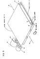
- FIG. 5 is an isometric view of the transport system. Elements which are common to previously identified elements in FIG. 1 will be identified by the same numeral.
- the vacuum transport is disposed above the glass platen 12 of the convenience copier/duplicator.
- the junction of reference lines 49 and 50 identifies a reference corner of the platen.
- the vacuum transport includes the vacuum transport belt 52 mounted on rollers 24 and 26. Forward direction of belt motion is identified by arrow 34. The reverse direction of the belt is identified by arrow 36.
- Drive roller 24 is fixedly mounted to shaft 56.
- Two-phase tachometer 38 is coupled directly to shaft 56 and by means of drive belt 58 to bidirectional drive motor 28.
- the GRS 46 which senses the passage of a sheet, is disposed downstream from the vacuum belt 52 in the direction of forward belt motion.
- the present arrangement is capable of registering a sheet at any point on the document platen of the convenience copier without the use of mechanical gates.
- the sheet is fed by transport means 20 in the direction shown by arrow 22 on to the belt.
- the transport belt is driven by DC motor 28 and the leading edge of an attached sheet is driven past the glass reference position 14 beyond GRS 46 (FIG. 1) and then stopped.
- a control signal is generated by servo-control system means 30 on conductor 32 and the belt moves in the opposite direction identified by arrow 36.
- the servo-controlled system means 30 keeps check of the distance travelled by the belt.
- the edge of the sheet which was the leading edge when the belt was travelling in the direction shown by arrow 34 is now the trailing edge of the sheet.
- a signal is generated on conductor 48.
- This trailing edge signal is utilized by the servo control means to recalibrate servo control means and to generate the required dynamics for the belt so that the attached document is disposed in alignment with the registration zone on the platen.
- GRS 46 could be used to detect and position the leading edge of the document.
- the glass reference sensor 46 is positioned at the confluence or junction of simplex path 64, duplex path 62 and platen path 63. Multiple paths may also occur at the junction where the paper paths of a semiautomatic document feeder (SADF) and an automatic document feeder (ADF) or a recirculating document feeder (RADF) intersect.
- SADF semiautomatic document feeder
- ADF automatic document feeder
- RDF recirculating document feeder
- the transport belt 52 is mounted with drive roller 24 above the document exposure platen 12 of the convenience copier/duplicator.
- the forward direction of belt motion is from right to left in the direction shown by arrow 34. It should be noted that when a sheet is copied on one side only, the sheet is attached to the belt on the right side of FIG. 8 and transferred by the belt to the registration zone of the glass.
- the sheet After copying, the sheet is transferred in simplex path 64 in the direction of arrow 67 and is returned to the support tray (not shown) of the RADF.
- the sheet is driven in the direction of arrow 66 and it is returned in the direction of arrow 68, along path 64 for copying of the second side.
- Back-up roller 70 assists the sheet in attaching to the vacuum belt as it is returned from the duplex path onto the belt.
- the trailing edge of the sheet is used to activate the servo-controlled system means 30 (FIG. 1) which initiates the control signals which control the belt to position the sheet at the proper registration zone on the document platen 12.
- the leading edge 72 of the document covers the sensor and the output signal from the sensor changes levels.
- the control system is conditioned so that the positioning algorithm is not initiated.
- the trailing edge 74 of the document clears the sensor, again the GRS 46 state is changed.
- the signal generated by the trailing edge is a signal used to initiate the positioning algorithm function.
- the trailing edge of the document is used to initiate the position trajectory algorithm which is used to control the belt to eliminate sensor hysteresis so that the document is positioned at the proper registration zone.
- a single sensor is used for registering sheets on the document platen for simplex and/or duplex copying.
- FIG. 2 is a block diagram of the servo-control system means 30.
- the function of the servo-control system means 30 is to generate control signals which force DC motor 28 to follow a particular position trajectory which transports the vacuum transport belt to position an attached document at a specific registration zone on the document platen 12 (F IG . 1).
- the servo-control system means 30 includes a closed loop servo system coupled to a controller 73.
- controller 73 may be configured from combinatorial logic circuit, in the preferred embodiment of this invention, it is a conventional microcomputer, for example, the M6800 manufactured by Motorola Semiconductive Products, Inc. Since microcomputers are well known in the art, details of the M6800 will not be given. Suffice it to say that its instruction set to generate the necessary electrical signals to accelerate and decelerate the belt so that the attached document will be placed at the registration zone.
- the motion is monitored by the two-phase tachometer 38.
- two sets of pulses are outputted on conductors 40 and 42, respectively.
- the set of pulses outputted on conductor 40 lead those on conductor 42.
- the set of pulses on conductor 40 lag those on conductor 42.
- the signals on conductors 40 and 42 are fed into tachometer (TAC) processing means 74.
- TAC tachometer
- the tachometer processing means 74 includes combinational circuits which accept the pulses on conductors 40 and 42 and generate backward (BKWD) pulses on conductor 76 and forward (FWD) pulses on conductor 78.
- BKWD backward
- FWD forward
- the use of combinational circuits for generating backward and forward pulse from a two-phase tach is shown in an article entitled "Logical Motion and Direction Detection" by H. C. Jackson in the IBM Technical Disclosure Bulletin, Volume 14, No. 12, May 1972 (pgs. 3672-3673).
- the forward and backward pulses on conductors 76 and 78, respectively, are fed into logic circuit means 80.
- the logic circuit means 80 include an up/down counter accepts reference clock pulses 89 from microcomputer 73 and sums the reference clock pulses with the forward and/or backward pulses to generate servo error signal (called 2) which is outputted on buss 82.
- the reference clock pulses 89 are a series of time-modulated pulses generated to obtain the desired position trajectory.
- the logic circuits of the logic circuit means 80 accepts directional signals from the microcomputer on simplex buss 84. The directional signal is generated by the microcomputer and instructs the circuitry to drive the belt right or left so that the sheet which is attached to the belt is positioned at the predetermined location on the document platen.
- Command input to microprocessor 73 is supplied on command interface multiplexor buss 86.
- Information such as the direction of belt motion, that is right or left, and position whereat the sheet must be registered from the glass reference sensor (GRS) 46 (FIG. 1) is supplied on buss 86.
- GRS glass reference sensor
- the command information such as position from the GRS sensor whereat the sheet must be registered, can be supplied from a bank of switches which would be attached to the instrument panel of the copier/ duplicator. Alternately, the information can be supplied by microcode on buss 86 or from another microprocessor.
- the signal on conductor 48 is generated by the glass reference sensor and indicates to the microprocessor that an edge of the sheet has passed the glass reference sensor. As will be explained subsequently, this level change is utilized by the microprocessor to initiate a series of calculations which generate a position trajectory which forces the belt to position an attached sheet at the predetermined registration zone.
- the error signal outputted from logic circuit means 80 is fed over multiplexor buss 88 to the microcomputer 73. As will be described subsequently, the error signal on buss 88 is utilized in the algabraic calculation by the microcomputer.
- the error signal information is fed over buss 82 into bipolar digital-analog converter (DAC) 90. A bipolar DAC is necessary because the belt has to be moved bidirectionally.
- the DAC converts the digital signal into analog signal.
- the output of the DAC is coupled by conductor 92 into a loop compensation circuit means 94.
- the loop compensation circuit means 94 stabilizes the servo loop and prevents the same from oscillating.
- the output from the loop compensating network is fed over conductor 96 into power amplifier 98.
- the power amplifier amplifies the signal which it receives and drives belt motor 28 over conductor 100.
- the present system enables the electronic registration of the sheet at a particular registration zone on the copier platen so that side one (simplex registration) of the sheet can be copied and side two (duplex registration) of the sheet can be copied.
- side one simultaneous registration
- side two duplex registration
- the belt is moving right to left and accepts document 18 from transport means 20.
- the belt continues its motion and moves the sheet to the left.
- the belt is moved from right to left under the control of servo-control system means 30 so that the sheet is positioned at the predetermined registration zone.
- FIG. 3 shows a timing diagram for a short move and will be used to explain the positioning of a sheet so that side one of the sheet is copied.
- the first curve represents a plot of belt velocity versus time.
- the second curve represents the change in signal level as the trailing edge of the sheet clears the glass reference sensor (GRS) relative to time. The signal is generated as the sheet travels from left to right.
- the third curve shows a plot of distance moved by the belt versus time. It should be noted that there is a relationship between the process step to be performed and the time when the step is performed. To this end common numerals are used to identify the process steps below and to identify the corresponding times on the timing diagram of FIG. 3. With reference to FIG.
- the first curve represents a plot of velocity versus time
- the second curve represents the change in signal level outputted from the glass reference sensor (GRS) as a trailing edge of a sheet passes over said sensor.
- the third curve represents a distance versus time plot.
- distance refers to the distance that the belt moves with the attached sheet.
- a long move refers to a move wherein the motor reaches steady state velocity.
- Step 1 below occurs at 1 (FIG. 4).
- Step 3 occurs at 3 (FIG. 4) and so on.
- FIG. 9 a registration timing diagram for side two (that is duplex) copying of a document is shown.
- the first curve viewing from top to bottom, represents a velocity versus time plot.
- Curve two represents the point in time when the trailing edge of the attached sheet passes the GRS.
- the third curve represents a time distance plot.
- FIGS. 6A and 6B show a flowchart of the process step used to program the microprocessor 73.
- the first step in the flowchart is identified by decisional block 102.
- the function of the block is to indicate that computer 73 is looking for a start command at command interface 86.
- the program executes the start belt to the right routine identified by the functional block 104.
- the program starts reference (REF) pulse counter identified by functional block 106.
- the reference pulse counter is a counter located in the microcomputer. With the reference pulse counter started, the program next reads in T from the command interface.
- the read-in function is identified by functional block 108. Next the program enters decisional block 110.
- Decisional block 110 checks to see that the glass reference sensor (GRS) is clear. If the glass reference sensor is not clear, the program enters into a loop and continues to check until the sensor is cleared. Once the sensor is cleared, the program accesses the functional block 112. In functional block 112, the program reads in the servo error E on multiplexor buss 82 (FIG. 2). The program then enters functional block 114. In functional block l14 the program obtains the count in the reference clock counter. The program then enters functional block 116 and calculates R 0 +T 0 + ⁇ . From functinal block 116, the program enters decisional block 118. In decisional block 118 the program tests to see if R 0 +T 0 + ⁇ is less than or equal to 2T a . As was stated previously, this test indicates if the move is a short move.
- the program enters functional block 120 and calculates M 0 . As stated previously, M is equal to (R 0 +T 0 + ⁇ ) ⁇ 2.
- the program next enters functional block 122 (FIG. 6B) and continues to count reference clock pulses. From functional block 122, the program enters decisional block 124. In decisional block 124, the program tests to see if the reference clock count is equal to M 0 . If the result is negative, the program enters into a loop and performs the function identified in block 122. If the result is positive, the program then performs the function identified in functional block 126 and the belt is stopped, positioning the paper at the desired registration zone.
- the move is a long move.
- the program then enters and performs the function identified by functional block 128 (that is calculate R 0 +T 0 + ⁇ -T a ). Once the calculation is completed, the program performs the function identified by block 130, (i.e., continue to accelerate the belt until the reference clock count equals T). The belt is then switched to steady state run velocity V 0 . From block 130, the program enters functional block 132 (FIG, 6B). In functional block 132, the program continues to count reference clock pulses. The program then enters decisional block 134.
- decisional block 134 the program tests to see if the reference clock count is equal to R 0 +T 0 + ⁇ -T a . If the result is a negative, the program enters into a loop and will redo the function described in block 132. If the decision is positive, the program enters decisional block 136 and stops the belt positioning the attached document at the proper registration zone on the glass platen.
- Block 138 is an entry block wherein some basic assumptions are being made. It is assumed that the original document is attached to the belt and covering the GRS sensor (FIG. 8). It is further assumed that the belt is running to the right with a steady state (ss) velocity V 0 .
- the program then enters functional block 140. In functional block 140, the program reads TO from the command interface. The program then enters decisional block 142 and checks to see that the glass reference sensor is clear. If the sensor is not clear, the program enters into a loop. When the sensor is clear, the program enters functional block 144.
- the program reads in the servo error E from buss 88 (FIG. 2). The program then enters functional block 146 and calculates T 0 + ⁇ -T a . The program then enters functional block 148 where it starts the reference clock counter. The program next enters functional block 150 where it counts the reference clock pulses accumulated in the counter identified in step 148. The program then enters decisional block 152 and tests to see if the reference clock count is equal to T 0 +E-T a . If it is not, then the program enters a loop and continues until the reference count equals TO+E-T a . When this occurs, the program enters functional block 154, where it stops the belt and the document is now placed at the proper registration zone for duplex copying.
Landscapes
- Physics & Mathematics (AREA)
- General Physics & Mathematics (AREA)
- Exposure Or Original Feeding In Electrophotography (AREA)
- Registering Or Overturning Sheets (AREA)
- Delivering By Means Of Belts And Rollers (AREA)
- Holders For Sensitive Materials And Originals (AREA)
Abstract
Description
- The present invention relates to sheet feed and registration methods and systems.
- There are many machines and systems which employ sheet registration devices, such devices are used, for example in sheet stackers and printing machines. The present invention has particular, but not enclusive, value in electrophotographic document reproduction machines for the feed and registration of original documents for exposure.
- The use of registration devices in automatic document feeders (A.D.F.) or semi-automatic document feeders (SADF) in document reproduction machines is well known. Most employ a mechanical registration gate against which an edge of a document to be copied is aligned. Examples of such arrangements are shown in U.S. Patent Specification Nos. 4,242,316, 4,176,945 and 4,179,215. It has been found, however, that for high speed devices, the use of such mechanical gates can cause damage to documents and various arrangements have been proposed to replace such mechanical registration on the exposure platen of reproduction machines. In an arrangement described in an article entitled 'Document Feeder Without Register Gates' by C J Mahler, which appeared in the Xerox Disclosure Journal, Vol. 2, No. 3, May/ June 1977, at
page 49, a sheet is first registered prior to entry on to the platen. It is then positioned on the platen a precise fixed distance from the registration position. Though no registration device is used on the platen, this arrangement suffers from the same disadvantage as those mentioned above as a mechanical registration gate is employed. - A device similar to that shown in the Mahler article is shown in U.S. Patent Specification No. 4,066,255. In this system, instead of a mechanical gate prior to the platen, a trip switch is employed. As a sheet being fed trips the switch, an electromechanical control system causes the sheet feed system to continue feeding the sheet to a registration position a fixed distance from the switch. This system suffers from the disadvantage that with high speed feed, it is extremely difficult to effect precise alignment from the switch position. This difficulty is in part resolved in the system shown in an article by T N Taylor, entitled 'Document Registration System', which appeared in the Xerox Disclosure Journal, Vol. 3, No. 2, March/April 1978, at page 123. In that system the document is fed over the platen to a point beyond the registration position and then reversed to this position. Though this system permits faster initial feed over the platen, it requires a sheet to be stopped precisely at said point, which is registered by means of a switch or sensor. Thereafter, it is stated that the feed belt must be immediately, but gently and slowly, reversed to reverse the sheet feed for a fixed short distance equal to a fixed difference between said point and the desired document position on the platen.
- The present arrangement is of a similar type to the last mentioned prior art arrangement. However, it does not suffer from the disadvantage that a sheet is precisely aligned at the point beyond the platen. Instead, all that is required is that the sheet passes this point. Thus sheet feed velocity can be considerably increased. Furthermore, instead of reversing the sheet a short, fixed distance, the reversal is performed over a calculated distance, which can, therefore, be varied to accomodate various sheet sizes and various registration positions.
- Accordingly, the present invention provides a sheet feed and registration system including a platen upon which a sheet is to be registered, sheet feed means for feeding a sheet to, and over, the platen, and drive means for driving the sheet feed means bidirectionally, characterised by a sheet sensor positioned in the path of sheet feed away from the platen and control means coupled to the drive means and sheet sensor, said control means being operative, in response to signals from the sensor indicating that a sheet has passed over the platen in one direction over the sensor position and then passed from the sensor position back towards the platen in the opposite direction, to control movement of the sheet in said opposite direction from the sensor position to a calculated registration position on the platen.
- The invention further provides a method of feeding and registering a sheet on a platen characterised by the steps of feeding the sheet over the platen in one direction to a position past a point beyond the platen and thereafter reversing the feed to return the sheet to a registration position on the platen at a calculated distance from said point.
- The invention will now be described, by way of example, with reference to the accompanying drawings, in which:
- FIG. 1 shows a document feed and registration system embodying the present invention;
- FIG. 2 shows details of the servo-control system employed in the FIG. 1 system;
- FIG. 3 shows the velocity and the distance profile of the feed system for a short move;
- FIG. 4 shows the velocity and distance profile for a long move;
- FIG. 5 is an isometric view of the FIG. 1 system;
- FIGS. 6A and 6B show a flowchart of the process steps used to program the servo controller to enable the copying of side one of a document;
- FIG. 7 shows a flowchart of the process steps used to program the servo controller to enable the copying of side two of a document;
- FIG. 8 shows an embodiment of the present invention where the glass reference sensor is mounted at the junction of a plurality of document paths; and
- FIG. 9 shows the velocity and distance profile for side two registration of a document.
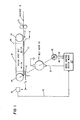
- FIG. 1 shows a copier/duplicator system embodying an electronic registration paper gate. The copier/duplicator system is fitted with an
exposure platen 12. As is known to those skilled in the art, theexposure platen 12 is transparent and has aforward registration position 14 and arear registration position 44. A document to be copied is positioned on the glass so that the leading edge of the document is in alignment withglass registration position 14. The document is then illuminated by the illumination system of the copier (not shown). As a result of the illumination, a latent or electrostatic image of the original document is formed on the photoconductive surface (not shown) of the copy. The electrostatic image is then transported to a plurality of processing stations where it is toned or developed and transferred to a supporting media. Sll og these components and/or processing stations are well known, and therefore, are not shown in the drawings nor will be described in detail. - Returning to FIG. 1, a recirculating automatic document feeder (RADF) 16 is mounted to the frame of the copier/
duplicator 10. The RADF is usually fitted with a support tray in which original documents to be copied are loaded. Adocument 18 to be copied is removed from the tray and is delivered by transport means 20 to the transport section ofRADF 16. It is then transported across the platen by a vacuum transport belt entrained overrollers -
Drive roller 24 is coupled to the shaft of a bidirectional servo-controlledbelt motor 28. Depending on the energization signal generated by servo-controlledsystem 30 onconductor 32, the belt can be transported bidirectionally in the directions identified byarrows exposure platen 12. - A direction/
position sensor 38 in the form of a two-phase tachometer is coupled to the shaft of the DC motor. The tachometer output pulses onconductors control system 30. The servo-control system generates signals onconductor 32 which are coupled toDC motor 28 to form a closed-loop servo system. - A glass reference sensor (GRS) 46 is disposed off the
exposure platen 12. The sensor is mounted so that a document, which is transported by the vacuum transport belt past theglass reference position 14 to a point beyond the sensor, can be sensed. As a document is sensed, the sensor provides a signal onconductor 48. This signal is applied to the servo-control system means 30 to initiate an algorithm which drives the DC bidirectional motor so that the vacuum transport belt with an attached document can be positioned atregistration position glass reference sensor 46 and theregistration zone 14 on the document platen is identified as T . - FIG. 5 is an isometric view of the transport system. Elements which are common to previously identified elements in FIG. 1 will be identified by the same numeral. The vacuum transport is disposed above the
glass platen 12 of the convenience copier/duplicator. The junction ofreference lines vacuum transport belt 52 mounted onrollers arrow 34. The reverse direction of the belt is identified byarrow 36. Driveroller 24 is fixedly mounted toshaft 56. Two-phase tachometer 38 is coupled directly toshaft 56 and by means ofdrive belt 58 tobidirectional drive motor 28. When the motor is energized with the proper polarity, the belt is transported in the forward direction identified byarrow 34 or in the reverse direction identified byarrow 36. TheGRS 46 which senses the passage of a sheet, is disposed downstream from thevacuum belt 52 in the direction of forward belt motion. - The present arrangement is capable of registering a sheet at any point on the document platen of the convenience copier without the use of mechanical gates. When one side of a sheet is to be copied, the sheet is fed by transport means 20 in the direction shown by
arrow 22 on to the belt. The transport belt is driven byDC motor 28 and the leading edge of an attached sheet is driven past theglass reference position 14 beyond GRS 46 (FIG. 1) and then stopped. A control signal is generated by servo-control system means 30 onconductor 32 and the belt moves in the opposite direction identified byarrow 36. As the belt moves to the right, that is, in the direction identified byarrow 36, the servo-controlled system means 30 keeps check of the distance travelled by the belt. It should be noted that the edge of the sheet which was the leading edge when the belt was travelling in the direction shown byarrow 34, is now the trailing edge of the sheet. As the trailing edge of the sheet clears sensor means 46, a signal is generated onconductor 48. This trailing edge signal is utilized by the servo control means to recalibrate servo control means and to generate the required dynamics for the belt so that the attached document is disposed in alignment with the registration zone on the platen. It should be noted thatGRS 46 could be used to detect and position the leading edge of the document. - Referring now to FIG. 8, the
glass reference sensor 46 is positioned at the confluence or junction ofsimplex path 64,duplex path 62 andplaten path 63. Multiple paths may also occur at the junction where the paper paths of a semiautomatic document feeder (SADF) and an automatic document feeder (ADF) or a recirculating document feeder (RADF) intersect. As before, thetransport belt 52 is mounted withdrive roller 24 above thedocument exposure platen 12 of the convenience copier/duplicator. The forward direction of belt motion is from right to left in the direction shown byarrow 34. It should be noted that when a sheet is copied on one side only, the sheet is attached to the belt on the right side of FIG. 8 and transferred by the belt to the registration zone of the glass. After copying, the sheet is transferred insimplex path 64 in the direction ofarrow 67 and is returned to the support tray (not shown) of the RADF. However, for duplex copying, after side one of the sheet is copied, it is driven in the direction ofarrow 66 and it is returned in the direction of arrow 68, alongpath 64 for copying of the second side. Back-uproller 70 assists the sheet in attaching to the vacuum belt as it is returned from the duplex path onto the belt. - As with the simplex copying previously described, in the duplex copying the trailing edge of the sheet is used to activate the servo-controlled system means 30 (FIG. 1) which initiates the control signals which control the belt to position the sheet at the proper registration zone on the
document platen 12. Assuming that a document identified bynumeral 71 is returned to the document platen for side two copying, the leadingedge 72 of the document covers the sensor and the output signal from the sensor changes levels. However, the control system is conditioned so that the positioning algorithm is not initiated. As the trailingedge 74 of the document clears the sensor, again theGRS 46 state is changed. The signal generated by the trailing edge is a signal used to initiate the positioning algorithm function. It is therefore evident that whether it be simplex registration for one side copying or duplex registration for two side copying, the trailing edge of the document is used to initiate the position trajectory algorithm which is used to control the belt to eliminate sensor hysteresis so that the document is positioned at the proper registration zone. By using the trailing edge of the document, a single sensor is used for registering sheets on the document platen for simplex and/or duplex copying. - FIG. 2 is a block diagram of the servo-control system means 30. The function of the servo-control system means 30 is to generate control signals which force
DC motor 28 to follow a particular position trajectory which transports the vacuum transport belt to position an attached document at a specific registration zone on the document platen 12 (FIG. 1). The servo-control system means 30 includes a closed loop servo system coupled to acontroller 73. Althoughcontroller 73 may be configured from combinatorial logic circuit, in the preferred embodiment of this invention, it is a conventional microcomputer, for example, the M6800 manufactured by Motorola Semiconductive Products, Inc. Since microcomputers are well known in the art, details of the M6800 will not be given. Suffice it to say that its instruction set to generate the necessary electrical signals to accelerate and decelerate the belt so that the attached document will be placed at the registration zone. - Still referring to FIG. 2, as the
belt motor 28 rotates clockwise or counterclockwise, the motion is monitored by the two-phase tachometer 38. Depending on the direction of the motor rotation, two sets of pulses are outputted onconductors conductor 40 lead those onconductor 42. If the motor rotates counterclockwise, the set of pulses onconductor 40 lag those onconductor 42. The signals onconductors conductors conductor 76 and forward (FWD) pulses onconductor 78. The use of combinational circuits for generating backward and forward pulse from a two-phase tach is shown in an article entitled "Logical Motion and Direction Detection" by H. C. Jackson in the IBM Technical Disclosure Bulletin,Volume 14, No. 12, May 1972 (pgs. 3672-3673). The forward and backward pulses onconductors reference clock pulses 89 frommicrocomputer 73 and sums the reference clock pulses with the forward and/or backward pulses to generate servo error signal (called 2) which is outputted onbuss 82. Thereference clock pulses 89 are a series of time-modulated pulses generated to obtain the desired position trajectory. The logic circuits of the logic circuit means 80 accepts directional signals from the microcomputer onsimplex buss 84. The directional signal is generated by the microcomputer and instructs the circuitry to drive the belt right or left so that the sheet which is attached to the belt is positioned at the predetermined location on the document platen. - Command input to
microprocessor 73 is supplied on commandinterface multiplexor buss 86. Information such as the direction of belt motion, that is right or left, and position whereat the sheet must be registered from the glass reference sensor (GRS) 46 (FIG. 1) is supplied onbuss 86. There are a plurality of ways that can be used to present the command information onbuss 86. The command information such as position from the GRS sensor whereat the sheet must be registered, can be supplied from a bank of switches which would be attached to the instrument panel of the copier/ duplicator. Alternately, the information can be supplied by microcode onbuss 86 or from another microprocessor. - The signal on
conductor 48 is generated by the glass reference sensor and indicates to the microprocessor that an edge of the sheet has passed the glass reference sensor. As will be explained subsequently, this level change is utilized by the microprocessor to initiate a series of calculations which generate a position trajectory which forces the belt to position an attached sheet at the predetermined registration zone. In addition to the level change outputted from the GRS, the error signal outputted from logic circuit means 80 is fed overmultiplexor buss 88 to themicrocomputer 73. As will be described subsequently, the error signal onbuss 88 is utilized in the algabraic calculation by the microcomputer. The error signal information is fed overbuss 82 into bipolar digital-analog converter (DAC) 90. A bipolar DAC is necessary because the belt has to be moved bidirectionally. The DAC converts the digital signal into analog signal. The output of the DAC is coupled byconductor 92 into a loop compensation circuit means 94. The loop compensation circuit means 94 stabilizes the servo loop and prevents the same from oscillating. The output from the loop compensating network is fed overconductor 96 intopower amplifier 98. The power amplifier amplifies the signal which it receives and drivesbelt motor 28 overconductor 100. - Before describing the series of process steps which must be followed in order to position a document at a registration zone on the document platen, the following variables will be defined. Each variable will be used in performing the necessary calculations needed in order to position the sheet at the predetermined registration zone.
- 1) T (FIG. 1) defines the distance that the registration zone is from the glass reference sensor. This distance can be defined by the number of tach pulses between GRS and the registration point.
- 2) Σ is the servo error generated as the difference between the feed-back pulses and the references (REF) clock pulses generated by the microcomputer (FIG. 2).
- 3) T.. represents the number of reference (REF) clock pulses a generated to accelerate the belt from zero to its steady state (ss) velocity V , or to decelerate the belt from its ss velocity o Vo to zero. Each reference clock pulse generated by the computer 73 (FIG. 2) is equivalent to a tach pulse generated by
tach 38. - 4) R is the number of reference clock pulses that have been generated (distance) when the belt moves in a left to right direction from a point where the attached sheet covers the glass reference sensor until the trailing edge of the attached sheet clears the sensor.
- 5) M o represents the midpoint distance whereat the belt must begin deceleration for the sheet to be aligned with the registration zone.
- 6) A short move is defined as a move where the sheet is moved from a point over the glass reference sensor to its registration zone without the
belt motor 28 reaching steady state velocity. - 7) A long move is defined as a move where the attached sheet is moved from a point covering the glass reference sensor to its registration zone on the glass platen with the motor reaching steady state velocity.
- As was stated previously, the present system enables the electronic registration of the sheet at a particular registration zone on the copier platen so that side one (simplex registration) of the sheet can be copied and side two (duplex registration) of the sheet can be copied. To this end, and with reference to FIG. 1, it is assumed that the belt is moving right to left and accepts
document 18 from transport means 20. The belt continues its motion and moves the sheet to the left. Thereafter, the belt is moved from right to left under the control of servo-control system means 30 so that the sheet is positioned at the predetermined registration zone. - FIG. 3 shows a timing diagram for a short move and will be used to explain the positioning of a sheet so that side one of the sheet is copied. Viewing the curves from top to bottom, the first curve represents a plot of belt velocity versus time. The second curve represents the change in signal level as the trailing edge of the sheet clears the glass reference sensor (GRS) relative to time. The signal is generated as the sheet travels from left to right. The third curve shows a plot of distance moved by the belt versus time. It should be noted that there is a relationship between the process step to be performed and the time when the step is performed. To this end common numerals are used to identify the process steps below and to identify the corresponding times on the timing diagram of FIG. 3. With reference to FIG. 1, it is assumed that the document to be registered is securely attached to the undersurface of the transport belt. It is also assumed that the direction of forward belt motion is identified by
arrow 34. The direction of backward or reverse belt motion is identified byarrow 36. It is further assumed that the leading edge of the attached document extends beyond theGRS 46. It is assumed that the initial conditions are satisfied prior to the initiating of the following process steps: - Step 1: Upon command, accelerate the belt to the right and read in T0 from the command interface 86 (FIG. 2).
- Step 2: Count reference clock pulses (R0) until glass reference sensor (GRS) clears.
- Step 3: When GRS clears, read in servo error (Σ) and get R . It should be noted that when GRS is cleared the level signal outputted from the sensor changes (see FIG. 3).
- Step 4: Determine that move is a short move. The move is short if R0+T0+Σ is less than or equal to 2Ta. As pointed out before by definition, Ta is the distance moved by the belt from zero velocity until the motor reaches steady state. R0 is obtained by interrogating the counter in microprocessor 73 (FIG. 2) which generates the reference clock pulses.
- Step 5: Calculate the middistance (M ) of move (see FIG. 3). (MO = (R0+T0+Σ) divided by 2)
- Step 6: Continue to accelerate the belt and count reference clock pulses.
- Step 7: When the count of the reference pulses equals M0, decelerate belt from a count of M0 reference clock pulses to a count of 0.
- Step 8: The belt velocity will be zero and the paper is now positioned correctly at the glass registration zone. The process is now completed for side one registration.
- Referring now to FIG. 4, simplex (that is side one) registration of a sheet with a long move is shown. Identifying the curves from top to bottom, the first curve represents a plot of velocity versus time, the second curve represents the change in signal level outputted from the glass reference sensor (GRS) as a trailing edge of a sheet passes over said sensor. The third curve represents a distance versus time plot. As before, distance refers to the distance that the belt moves with the attached sheet. As was defined above, a long move refers to a move wherein the motor reaches steady state velocity. As before, the process steps for the long move will now be described. Numerals in the enunciated process step which correspond with particular times on the curves of FIG. 4 will be identified with the same numeral. By way of example,
Step 1 below occurs at 1 (FIG. 4).Step 3 occurs at 3 (FIG. 4) and so on. Some of the steps below are calculations. As such, there is no corresponding numeral on the Figure. - Step 1: Upon command, accelerate the belt to the right and read in T0 from the command interface 86 (FIG. 2).
- Step 2: Count reference clock pulses (R ) until GRS clears. As stated before, the reference clock pulses are generated by appropriate programming of the
microcomputer 73. - Step 3: When GRS clears, read in the servo error E and get R . As is identified by numeral 3 in FIG. 4, when GRS clears, a pulse is outputted from the sensor, that is there is a change in signal level.
- Step 4: Determine that move is long (that is move distance larger than 2Ta). Stated algebraically, (R0+T0+Σ) > 2Ta.
- Step 5: Calculate (R0+T0+Σ-Ta) to obtain belt decelerate count.
- Step 6: Continue to accelerate belt until reference clock count equals T . At this point, switch belt to steady state a velocity VO.
- Step 7: Continue to count reference clock pulses.
- Step 8: When reference clock count equals (R0+T0+Σ-Ta) decelerate belt for T reference clock pulses to stop belt. a
- Step 9: Paper is now positioned correctly on glass.
- Referring now to FIG. 9, a registration timing diagram for side two (that is duplex) copying of a document is shown. By way of example, and with reference to FIGS. 1 and 8, for side two copying it is assumed that the belt is in motion at steady state velocity from the left to right. In FIG. 9, the first curve, viewing from top to bottom, represents a velocity versus time plot. Curve two represents the point in time when the trailing edge of the attached sheet passes the GRS. The third curve represents a time distance plot. As before, process steps to be described which correspond with timing are identified by identical numerals. In order to register side two of the document, the following series of process steps must be performed.
- Step 1: It is assumed that the belt is moving from left to right at steady state velocity (V ) and has already accepted the document with side two facing the copy platen.
- Step 2: Read in T0 from the command interface.
- Step 3: Look for GRS to clear. As is seen in FIG. 9, GRS clears when there is a change in the signal level outputted from glass reference sensor.
- Step 4: When GRS clears, read in the servo error E and start counting reference clock pulses.
- Step 5: Calculate point where belt is to begin deceleration. The point where the belt is to be decelerated occurs when the reference clock count is equal to T0+Σ-Ta.
- Step 6: When reference clock count is equal to T0+Σ-Ta decelerate belt for Ta reference clocks to stop belt.
- Step 7: The paper is now positioned correctly on the glass.
- FIGS. 6A and 6B show a flowchart of the process step used to program the
microprocessor 73. The first step in the flowchart is identified bydecisional block 102. The function of the block is to indicate thatcomputer 73 is looking for a start command atcommand interface 86. Once the start command is received, the program executes the start belt to the right routine identified by thefunctional block 104. Once the belt begins to move to the right, the program starts reference (REF) pulse counter identified byfunctional block 106. The reference pulse counter is a counter located in the microcomputer. With the reference pulse counter started, the program next reads in T from the command interface. The read-in function is identified byfunctional block 108. Next the program entersdecisional block 110. Decisional block 110 checks to see that the glass reference sensor (GRS) is clear. If the glass reference sensor is not clear, the program enters into a loop and continues to check until the sensor is cleared. Once the sensor is cleared, the program accesses thefunctional block 112. Infunctional block 112, the program reads in the servo error E on multiplexor buss 82 (FIG. 2). The program then entersfunctional block 114. In functional block l14 the program obtains the count in the reference clock counter. The program then entersfunctional block 116 and calculates R0+T0+Σ. Fromfunctinal block 116, the program entersdecisional block 118. Indecisional block 118 the program tests to see if R0+T0+Σ is less than or equal to 2Ta. As was stated previously, this test indicates if the move is a short move. - If the test is true (that is yes), the program enters
functional block 120 and calculates M0. As stated previously, M is equal to (R0+T0+Σ) ÷ 2. The program next enters functional block 122 (FIG. 6B) and continues to count reference clock pulses. Fromfunctional block 122, the program entersdecisional block 124. Indecisional block 124, the program tests to see if the reference clock count is equal to M0. If the result is negative, the program enters into a loop and performs the function identified inblock 122. If the result is positive, the program then performs the function identified infunctional block 126 and the belt is stopped, positioning the paper at the desired registration zone. - If the test identified by decisional block 118 (FIG. 6A) is negative, the move is a long move. The program then enters and performs the function identified by functional block 128 (that is calculate R0+T0+Σ-Ta). Once the calculation is completed, the program performs the function identified by
block 130, (i.e., continue to accelerate the belt until the reference clock count equals T). The belt is then switched to steady state run velocity V0. Fromblock 130, the program enters functional block 132 (FIG, 6B). Infunctional block 132, the program continues to count reference clock pulses. The program then entersdecisional block 134. Indecisional block 134, the program tests to see if the reference clock count is equal to R0+T0+Σ-Ta. If the result is a negative, the program enters into a loop and will redo the function described inblock 132. If the decision is positive, the program entersdecisional block 136 and stops the belt positioning the attached document at the proper registration zone on the glass platen. - FIG. 7 shows a flowchart which can be used to program the microprocessor so that side two of a document is registered for duplex copying.
Block 138 is an entry block wherein some basic assumptions are being made. It is assumed that the original document is attached to the belt and covering the GRS sensor (FIG. 8). It is further assumed that the belt is running to the right with a steady state (ss) velocity V0. The program then entersfunctional block 140. Infunctional block 140, the program reads TO from the command interface. The program then entersdecisional block 142 and checks to see that the glass reference sensor is clear. If the sensor is not clear, the program enters into a loop. When the sensor is clear, the program enters functional block 144. In functional block 144, the program reads in the servo error E from buss 88 (FIG. 2). The program then entersfunctional block 146 and calculates T0+Σ-Ta. The program then entersfunctional block 148 where it starts the reference clock counter. The program next entersfunctional block 150 where it counts the reference clock pulses accumulated in the counter identified instep 148. The program then entersdecisional block 152 and tests to see if the reference clock count is equal to T0+E-Ta. If it is not, then the program enters a loop and continues until the reference count equals TO+E-Ta. When this occurs, the program entersfunctional block 154, where it stops the belt and the document is now placed at the proper registration zone for duplex copying.
Claims (8)
Applications Claiming Priority (2)
| Application Number | Priority Date | Filing Date | Title |
|---|---|---|---|
| US06/262,727 US4455018A (en) | 1981-05-11 | 1981-05-11 | Document feeder electronic registration gate |
| US262727 | 1981-05-11 |
Publications (2)
| Publication Number | Publication Date |
|---|---|
| EP0064591A1 true EP0064591A1 (en) | 1982-11-17 |
| EP0064591B1 EP0064591B1 (en) | 1986-06-11 |
Family
ID=22998764
Family Applications (1)
| Application Number | Title | Priority Date | Filing Date |
|---|---|---|---|
| EP82102507A Expired EP0064591B1 (en) | 1981-05-11 | 1982-03-25 | Sheet feed and registration method and system |
Country Status (5)
| Country | Link |
|---|---|
| US (1) | US4455018A (en) |
| EP (1) | EP0064591B1 (en) |
| JP (1) | JPS57186768A (en) |
| CA (1) | CA1181836A (en) |
| DE (1) | DE3271624D1 (en) |
Cited By (4)
| Publication number | Priority date | Publication date | Assignee | Title |
|---|---|---|---|---|
| EP0198371A1 (en) * | 1985-04-13 | 1986-10-22 | Alcatel SEL Aktiengesellschaft | Handling station for an original |
| EP0210707A1 (en) * | 1985-07-30 | 1987-02-04 | Océ-Nederland B.V. | Sheet positioning device |
| EP0627670A3 (en) * | 1989-07-27 | 1994-12-28 | Mita Industrial Co Ltd | |
| CN108483635A (en) * | 2018-06-06 | 2018-09-04 | 江苏联合创业环保有限公司 | Membrane bioreaction auxiliary device of aerobic circulating fluidized bed |
Families Citing this family (28)
| Publication number | Priority date | Publication date | Assignee | Title |
|---|---|---|---|---|
| DE3201403A1 (en) * | 1981-01-20 | 1982-08-12 | Canon K.K., Tokyo | AUTOMATIC DOCUMENT FEEDER |
| US4545031A (en) * | 1981-09-17 | 1985-10-01 | Kita Electrics Co., Ltd. | Photo-electric apparatus for monitoring printed papers |
| US4809969A (en) * | 1982-12-13 | 1989-03-07 | Savin Corporation | Automatic document feeder and registration system therefor |
| DE3301722C2 (en) * | 1983-01-20 | 1985-03-07 | Heidelberger Druckmaschinen Ag, 6900 Heidelberg | Method and device for the correct feeding of sheets to sheet processing machines |
| JPS6045235A (en) * | 1983-07-20 | 1985-03-11 | 株式会社サンエス | Original automatic feeder of copying machine |
| US4667951A (en) * | 1983-08-23 | 1987-05-26 | Canon Kabushiki Kaisha | Original feeding apparatus |
| JPS6078462A (en) * | 1983-10-06 | 1985-05-04 | Konishiroku Photo Ind Co Ltd | Recorder |
| US4558373A (en) * | 1984-05-11 | 1985-12-10 | Skantek Corporation | Automatic data capture system with special document handling prior to normal scanning |
| US4653008A (en) * | 1984-06-21 | 1987-03-24 | Iwatsu Electric Co., Ltd. | Method of controlling platemaking positions and errors |
| US4579444A (en) * | 1984-12-06 | 1986-04-01 | Xerox Corporation | Document registration system |
| JPS6374844A (en) * | 1986-09-18 | 1988-04-05 | Minolta Camera Co Ltd | Automatic original feeder |
| JPS63147152A (en) * | 1986-12-11 | 1988-06-20 | Ricoh Co Ltd | Copying machine with automatic document feeder |
| GB2214321B (en) * | 1988-01-22 | 1991-07-10 | Ricoh Kk | Copier with an automatic document feeder |
| US5056775A (en) * | 1989-07-12 | 1991-10-15 | Mita Industrial Co., Ltd. | Document feeder which properly positions a document on the platen |
| US4961090A (en) * | 1989-08-03 | 1990-10-02 | Xerox Corporation | Large media proportional copying system |
| US5105363A (en) * | 1989-10-10 | 1992-04-14 | Unisys Corporation | Servo means for document-transport |
| US4979730A (en) * | 1989-11-14 | 1990-12-25 | Pitney Bowes Inc. | Sheet drive system having an encoder apparatus |
| US5086319A (en) * | 1989-11-17 | 1992-02-04 | Xerox Corporation | Multiple servo system for compensation of document mis-registration |
| US5069436A (en) * | 1989-12-06 | 1991-12-03 | Eastman Kodak Company | Recirculating document feeder |
| US5026044A (en) * | 1990-07-02 | 1991-06-25 | Xerox Corporation | Dual mode document registration system |
| JPH05286606A (en) * | 1992-04-10 | 1993-11-02 | Konica Corp | Copying machine with automatic document feeding device |
| US5499804A (en) * | 1992-06-15 | 1996-03-19 | Mita Industrial Co., Ltd. | Paper conveying device and paper conveying method |
| US5600906A (en) * | 1995-10-03 | 1997-02-11 | Jet Sew Technologies, Inc. | Automatic suction type transfer of limp material on conveyors |
| JP3741071B2 (en) * | 2002-03-29 | 2006-02-01 | ブラザー工業株式会社 | Paper feeder |
| DE10234629A1 (en) * | 2002-07-29 | 2004-02-19 | Nexpress Solutions Llc | Method and device for providing sheets in a printing press |
| US7903143B2 (en) * | 2008-03-13 | 2011-03-08 | Dell Products L.P. | Systems and methods for document scanning using a variable intensity display of an information handling system |
| US8141870B2 (en) * | 2010-03-30 | 2012-03-27 | Lexmark International, Inc. | Methods for moving a media sheet within an imaging device |
| JP2012148878A (en) * | 2011-01-21 | 2012-08-09 | Seiko Epson Corp | Conveyance device and method |
Citations (5)
| Publication number | Priority date | Publication date | Assignee | Title |
|---|---|---|---|---|
| US3843915A (en) * | 1973-02-02 | 1974-10-22 | Ncr Co | Servo-motor control system including a two phase digital shaft position detector |
| DE2715429A1 (en) * | 1977-04-04 | 1978-10-12 | Mannesmann Ag | Form printing on continuous paper web - takes place while form is withdrawn line by line by pulling action actuated by feed chain drive |
| US4176945A (en) * | 1978-07-12 | 1979-12-04 | Eastman Kodak Company | Sheet feeding apparatus for use with copier/duplicators or the like |
| US4184673A (en) * | 1976-04-19 | 1980-01-22 | Veb Polygraph Leipzig Kombinat Fur Polygraphische Maschinen Und Ausrustungen | Method of and an apparatus for aligning sheets advancing in an overlapping array to a printing machine |
| EP0050508A2 (en) * | 1980-10-20 | 1982-04-28 | Ing. C. Olivetti & C., S.p.A. | Original feeder for copying machines |
Family Cites Families (9)
| Publication number | Priority date | Publication date | Assignee | Title |
|---|---|---|---|---|
| US3741357A (en) * | 1971-11-11 | 1973-06-26 | Ibm | Position controlling system |
| JPS5527344B2 (en) * | 1973-12-26 | 1980-07-19 | ||
| US4066255A (en) * | 1976-07-23 | 1978-01-03 | Addressograph-Multigraph Corporation | Document transport system |
| GB1599774A (en) * | 1977-02-10 | 1981-10-07 | Ricoh Kk | Document feeding apparatus |
| US4234261A (en) * | 1977-04-04 | 1980-11-18 | Mannesmann Aktiengesellschaft | Printer |
| JPS5482912A (en) * | 1977-12-15 | 1979-07-02 | Nec Corp | Facsimile transmitter |
| US4179215A (en) * | 1978-07-24 | 1979-12-18 | Eastman Kodak Company | Recirculating document feeder |
| US4243316A (en) * | 1979-07-25 | 1981-01-06 | Eastman Kodak Company | Registration mechanism |
| US4345751A (en) * | 1980-07-25 | 1982-08-24 | Eastman Kodak Company | Sheet feeding apparatus |
-
1981
- 1981-05-11 US US06/262,727 patent/US4455018A/en not_active Expired - Fee Related
-
1982
- 1982-03-12 JP JP57038258A patent/JPS57186768A/en active Granted
- 1982-03-23 CA CA000399186A patent/CA1181836A/en not_active Expired
- 1982-03-25 EP EP82102507A patent/EP0064591B1/en not_active Expired
- 1982-03-25 DE DE8282102507T patent/DE3271624D1/en not_active Expired
Patent Citations (5)
| Publication number | Priority date | Publication date | Assignee | Title |
|---|---|---|---|---|
| US3843915A (en) * | 1973-02-02 | 1974-10-22 | Ncr Co | Servo-motor control system including a two phase digital shaft position detector |
| US4184673A (en) * | 1976-04-19 | 1980-01-22 | Veb Polygraph Leipzig Kombinat Fur Polygraphische Maschinen Und Ausrustungen | Method of and an apparatus for aligning sheets advancing in an overlapping array to a printing machine |
| DE2715429A1 (en) * | 1977-04-04 | 1978-10-12 | Mannesmann Ag | Form printing on continuous paper web - takes place while form is withdrawn line by line by pulling action actuated by feed chain drive |
| US4176945A (en) * | 1978-07-12 | 1979-12-04 | Eastman Kodak Company | Sheet feeding apparatus for use with copier/duplicators or the like |
| EP0050508A2 (en) * | 1980-10-20 | 1982-04-28 | Ing. C. Olivetti & C., S.p.A. | Original feeder for copying machines |
Non-Patent Citations (1)
| Title |
|---|
| XEROX DISCLOSURE JOURNAL, vol. 2, no. 3, March/April 1978, pages 123 to 125, Stamford (USA); * |
Cited By (5)
| Publication number | Priority date | Publication date | Assignee | Title |
|---|---|---|---|---|
| EP0198371A1 (en) * | 1985-04-13 | 1986-10-22 | Alcatel SEL Aktiengesellschaft | Handling station for an original |
| EP0210707A1 (en) * | 1985-07-30 | 1987-02-04 | Océ-Nederland B.V. | Sheet positioning device |
| EP0627670A3 (en) * | 1989-07-27 | 1994-12-28 | Mita Industrial Co Ltd | |
| CN108483635A (en) * | 2018-06-06 | 2018-09-04 | 江苏联合创业环保有限公司 | Membrane bioreaction auxiliary device of aerobic circulating fluidized bed |
| CN108483635B (en) * | 2018-06-06 | 2020-10-30 | 江苏联合创业环保有限公司 | Membrane bioreaction auxiliary device of aerobic circulating fluidized bed |
Also Published As
| Publication number | Publication date |
|---|---|
| JPS6150863B2 (en) | 1986-11-06 |
| DE3271624D1 (en) | 1986-07-17 |
| CA1181836A (en) | 1985-01-29 |
| JPS57186768A (en) | 1982-11-17 |
| US4455018A (en) | 1984-06-19 |
| EP0064591B1 (en) | 1986-06-11 |
Similar Documents
| Publication | Publication Date | Title |
|---|---|---|
| EP0064591B1 (en) | Sheet feed and registration method and system | |
| US4416534A (en) | Apparatus and method for registering copy sheets in a variable pitch reproduction machine | |
| US4519700A (en) | Electronically gated paper aligner system | |
| US4585332A (en) | Electrophotographic printing machine with means for sensing size of document | |
| US4627711A (en) | Machine shutdown control | |
| EP0030282A1 (en) | Electrophotographic copier with reduction mode facility and control of scanning carriage | |
| EP0074483B1 (en) | Original document feed system for a copier | |
| US5086319A (en) | Multiple servo system for compensation of document mis-registration | |
| US4366219A (en) | Scanning optics copier with variable pitch copy capability | |
| US3729188A (en) | Document stacker apparatus | |
| JPS5825663A (en) | Copying machine | |
| US6708018B2 (en) | Image forming apparatus and sheet feeding method for use in the image forming apparatus | |
| US4577096A (en) | Multiple copy and transparency detector with illumination control | |
| US3848995A (en) | Copier/duplicator system | |
| EP0884652B1 (en) | Method and apparatus for detecting holes in copy media | |
| CA1037542A (en) | Copier/duplicator system | |
| JP3274042B2 (en) | Image forming device | |
| JP2558826B2 (en) | Image forming device | |
| US4947217A (en) | Image forming apparatus with control mechanism to correct any abberation in stopping position of original document | |
| JP2598006B2 (en) | Image forming device | |
| EP0795793A2 (en) | Image forming machine | |
| US5138397A (en) | Park position control apparatus for a sheet transport system | |
| JP2000034039A (en) | Sheet material conveying device and image forming device | |
| JPH06156797A (en) | Paper transport device of image forming device | |
| JPH1048759A (en) | Original scanning unit drive for copier |
Legal Events
| Date | Code | Title | Description |
|---|---|---|---|
| PUAI | Public reference made under article 153(3) epc to a published international application that has entered the european phase |
Free format text: ORIGINAL CODE: 0009012 |
|
| AK | Designated contracting states |
Designated state(s): DE FR GB IT NL |
|
| 17P | Request for examination filed |
Effective date: 19830322 |
|
| GRAA | (expected) grant |
Free format text: ORIGINAL CODE: 0009210 |
|
| AK | Designated contracting states |
Kind code of ref document: B1 Designated state(s): DE FR GB IT NL |
|
| REF | Corresponds to: |
Ref document number: 3271624 Country of ref document: DE Date of ref document: 19860717 |
|
| ET | Fr: translation filed | ||
| ITF | It: translation for a ep patent filed | ||
| PLBE | No opposition filed within time limit |
Free format text: ORIGINAL CODE: 0009261 |
|
| STAA | Information on the status of an ep patent application or granted ep patent |
Free format text: STATUS: NO OPPOSITION FILED WITHIN TIME LIMIT |
|
| 26N | No opposition filed | ||
| ITTA | It: last paid annual fee | ||
| PGFP | Annual fee paid to national office [announced via postgrant information from national office to epo] |
Ref country code: NL Payment date: 19900331 Year of fee payment: 9 |
|
| PGFP | Annual fee paid to national office [announced via postgrant information from national office to epo] |
Ref country code: DE Payment date: 19900402 Year of fee payment: 9 |
|
| PGFP | Annual fee paid to national office [announced via postgrant information from national office to epo] |
Ref country code: GB Payment date: 19910220 Year of fee payment: 10 |
|
| PGFP | Annual fee paid to national office [announced via postgrant information from national office to epo] |
Ref country code: FR Payment date: 19910225 Year of fee payment: 10 |
|
| PG25 | Lapsed in a contracting state [announced via postgrant information from national office to epo] |
Ref country code: NL Effective date: 19911001 |
|
| NLV4 | Nl: lapsed or anulled due to non-payment of the annual fee | ||
| PG25 | Lapsed in a contracting state [announced via postgrant information from national office to epo] |
Ref country code: DE Effective date: 19920101 |
|
| PG25 | Lapsed in a contracting state [announced via postgrant information from national office to epo] |
Ref country code: GB Effective date: 19920325 |
|
| GBPC | Gb: european patent ceased through non-payment of renewal fee | ||
| PG25 | Lapsed in a contracting state [announced via postgrant information from national office to epo] |
Ref country code: FR Effective date: 19921130 |
|
| REG | Reference to a national code |
Ref country code: FR Ref legal event code: ST |