US5600906A - Automatic suction type transfer of limp material on conveyors - Google Patents
Automatic suction type transfer of limp material on conveyors Download PDFInfo
- Publication number
- US5600906A US5600906A US08/538,220 US53822095A US5600906A US 5600906 A US5600906 A US 5600906A US 53822095 A US53822095 A US 53822095A US 5600906 A US5600906 A US 5600906A
- Authority
- US
- United States
- Prior art keywords
- conveyor
- workpiece
- limp
- leading edge
- limp workpiece
- Prior art date
- Legal status (The legal status is an assumption and is not a legal conclusion. Google has not performed a legal analysis and makes no representation as to the accuracy of the status listed.)
- Expired - Fee Related
Links
Images


Classifications
-
- B—PERFORMING OPERATIONS; TRANSPORTING
- B65—CONVEYING; PACKING; STORING; HANDLING THIN OR FILAMENTARY MATERIAL
- B65H—HANDLING THIN OR FILAMENTARY MATERIAL, e.g. SHEETS, WEBS, CABLES
- B65H29/00—Delivering or advancing articles from machines; Advancing articles to or into piles
- B65H29/26—Delivering or advancing articles from machines; Advancing articles to or into piles by dropping the articles
- B65H29/32—Delivering or advancing articles from machines; Advancing articles to or into piles by dropping the articles from pneumatic, e.g. suction, carriers
-
- B—PERFORMING OPERATIONS; TRANSPORTING
- B65—CONVEYING; PACKING; STORING; HANDLING THIN OR FILAMENTARY MATERIAL
- B65H—HANDLING THIN OR FILAMENTARY MATERIAL, e.g. SHEETS, WEBS, CABLES
- B65H29/00—Delivering or advancing articles from machines; Advancing articles to or into piles
- B65H29/24—Delivering or advancing articles from machines; Advancing articles to or into piles by air blast or suction apparatus
- B65H29/241—Suction devices
- B65H29/242—Suction bands or belts
-
- B—PERFORMING OPERATIONS; TRANSPORTING
- B65—CONVEYING; PACKING; STORING; HANDLING THIN OR FILAMENTARY MATERIAL
- B65H—HANDLING THIN OR FILAMENTARY MATERIAL, e.g. SHEETS, WEBS, CABLES
- B65H2406/00—Means using fluid
- B65H2406/30—Suction means
- B65H2406/32—Suction belts
- B65H2406/323—Overhead suction belt, i.e. holding material against gravity
-
- B—PERFORMING OPERATIONS; TRANSPORTING
- B65—CONVEYING; PACKING; STORING; HANDLING THIN OR FILAMENTARY MATERIAL
- B65H—HANDLING THIN OR FILAMENTARY MATERIAL, e.g. SHEETS, WEBS, CABLES
- B65H2511/00—Dimensions; Position; Numbers; Identification; Occurrences
- B65H2511/50—Occurence
- B65H2511/51—Presence
- B65H2511/514—Particular portion of element
-
- B—PERFORMING OPERATIONS; TRANSPORTING
- B65—CONVEYING; PACKING; STORING; HANDLING THIN OR FILAMENTARY MATERIAL
- B65H—HANDLING THIN OR FILAMENTARY MATERIAL, e.g. SHEETS, WEBS, CABLES
- B65H2515/00—Physical entities not provided for in groups B65H2511/00 or B65H2513/00
- B65H2515/30—Forces; Stresses
- B65H2515/34—Pressure, e.g. fluid pressure
Definitions
- the present application is directed to an automatic suction type transfer apparatus and method for transferring workpieces of limp material. More specifically, the transfer apparatus of the present application provides for transfer of a workpiece of a limp material (also known as a limp workpiece) from one conveyer to another without losing its orientation.
- the transfer apparatus and method enables transfer of a limp workpiece between conveyors operating or conveying at different speeds. Further, the transfer apparatus transfers the limp workpiece from a first conveyor to a second conveyor by creating a pressure differential and eliminates wrinkles in at least a portion of the limp workpiece during the aforementioned transfer.
- Known transfer apparatuses and methods enabled transfer of workpieces from one conveyor to another or enabled removal and stacking of workpieces previously traveling on a particular conveyor.
- the apparatus for conveying the workpiece on a type of transfer apparatus, or for removing workpieces from a conveyor included vacuum type apparatuses which used vacuum suction to contact the workpiece and to remove it from the conveyor.
- a first object of the present application is to alleviate the aforementioned known problems involving transfer of a limp workpiece from a first conveyor to a second conveyor.
- Another object of the present application is to alleviate the known problems involving transferring workpieces between conveyors of differing speeds.
- a still further object of the present application is to alleviate the problem of the creation of wrinkles in a limp workpiece during the transfer process, prior to conveying the workpiece on a next conveyor.
- a yet further object of the present application is to alleviate additional problems of transfer of limp materials of different sizes, shapes, and weights.
- step (d) terminating the pressure differential created in step (b), subsequent to step (c), to drop a middle portion of the limp workpiece excluding at least the leading edge, between the first and second conveyors to remove wrinkles from the limp workpiece;
- step (e) terminating the pressure differential created in step (b) subsequent to the conveying and clamping of step (d).
- a transfer apparatus for transferring a limp workpiece from a first conveyor to a second conveyor comprising:
- third means for conveying the leading edge of the limp workpiece to the second conveyor the second means terminating the created pressure differential subsequent to the third means conveying the leading edge to the second conveyor, to drop a middle portion of the limp workpiece excluding at least the leading edge, between the first and second conveyors to remove wrinkles from the limp workpiece, thereafter conveyed on the second conveyor.
- a transfer apparatus for transferring a limp workpiece from a first conveyor traveling at a first speed, to a second conveyor traveling at a second speed different from the first speed, comprising:
- third means for conveying at least the leading edge of the limp workpiece to the second conveyor, and for clamping at least the leading edge between both the third means and the second conveyor, both traveling at the second speed, the second means terminating the created pressure differential subsequent to the conveying of at least the leading edge of the limp workpiece to the second conveyor and the clamping of at least the leading edge of the limp workpiece between the third means and the second conveyor.
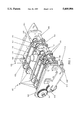
- FIG. 1 is an isometric view of an automatic suction type transfer apparatus of the present application
- FIG. 2 is an isometric view illustrating the automatic suction type transfer apparatus with one of the side plates removed in order to illustrate internal construction in conjunction with a first conveyor and a second conveyor;
- FIG. 3 is a block diagram illustrating the controller used in the automatic suction type transfer apparatus of the present application.
- FIGS. 4a-4h are schematic illustrations of different stages of operation of the automatic suction type transfer apparatus of the present application transferring the limp workpiece from a first conveyor to a second conveyor;
- FIG. 5 is a flow chart illustrating the operation of the automatic suction type transfer apparatus of the present application.
- FIG. 1 illustrates an automatic suction type transfer mechanism 100 of a first preferred embodiment of the present application.
- the transfer mechanism 100 will be described with regard to the interconnected parts used therein as shown in FIG. 1; with regard to the apparatus in conjunction with two conveyors, and connection and mounting of the apparatus to the conveyors in FIG. 2; with regard to the control unit used in the transfer mechanism 100 as shown in FIG. 3; and with regard to the operation of transferring a limp workpiece between two conveyors as shown in FIGS. 4a-h and as discussed in FIG. 5.
- the transfer mechanism 100 is shown in FIG. 1.
- the transfer mechanism 100 includes a mounting bracket 101 for mounting the transfer mechanism 100 on top of a conveyor. This is done, for example, by bolting down the mounting bracket 101 onto a frame of a conveyor.
- two mounting brackets 101 exist, one on either side of the transfer mechanism 100.
- Side plates 102 are connected to each of the mounting brackets 101. These side plates 102 support each of the drive shaft 103, fixed shaft 104, idler shaft 105 and vacuum chamber 106 of the transfer mechanism 100.
- Each of the drive shaft 103, fixed shaft 104, idler shaft 105, and vacuum chamber 106 are connected between the two side plates 102.
- the drive shaft 103 is supported by a bronze bushing on either end thereof and is free to rotate.
- the drive shaft 103 is further connected to a spur gear 107 mounted at one end, with the spur gear 107 being mounted outside of the side plate 102 as shown in FIG. 1.
- Further, between side plates 102 on the drive shaft 103 are knurled drive rollers 108.
- the outside diameter of each of these drive rollers 108 is preferably the same as the diameter of corresponding drive rollers on a second or post-conveyor 400, the conveyor which will receive the limp workpiece transferred from a first or pre-conveyor 300.
- a further spur gear 109 of the transfer mechanism 100 Connected to the drive shaft 430 for driving the drive rollers for the post-conveyor 400, as shown in FIG. 3, is a further spur gear 109 of the transfer mechanism 100, mounted at one end of drive shaft 430 and meshed with spur gear 107 as shown in FIG. 1.
- the spur gears 109 and 107 are then used to preferably operate the transfer mechanism 100 at the same traveling or conveying speed as that of the post-conveyor 400.
- the transfer mechanism 100 further includes a fixed shaft 104.
- This fixed shaft 104 includes crowned rollers 110 which are free to rotate on the fixed shaft 104.
- the crowned rollers 110 are maintained in place using collars 111 on either side of each crowned roller 110.
- the drive shaft 103 preferably operates at the same speed as the drive shaft 430 of the post-conveyor 400, with the drive shaft 103 further including knurled drive rollers 108 which rotate with the rotation of the drive shaft 103, to subsequently rotate crowned rollers 110 through connecting belts 118 as will be described subsequently.
- transfer mechanism 100 preferably includes a sensor mounting bracket 112, mounted on the fixed shaft 104. Mounted at another end of the sensor mounting bracket 112 is a photoelectric sensor 113. Operation and use of this photoelectric sensor 113 will be described hereafter.
- transfer mechanism 100 also includes a proximity switch 114 mounted using coupling brackets 115. Operation and use of this proximity switch 114 will be described hereafter.
- the idler shaft 105 as shown in FIG. 1 is also fixed and carries flanged rollers 116. These flanged rollers 116 are also free to rotate, and are maintained in place in a manner similar to crowned rollers 110, and are positioned using collars 111 on one side thereof and a tensioner bracket 117 on another side thereof. Flanged rollers 120, similar to rollers 116, are also mounted at the end of tensioner bracket 117 for producing tension in belts 118.
- These belts 118 are perforated (with holes therein) and travel around knurled drive rollers 108 of drive shaft 103, around flanged rollers 116 of idler shaft 105, between flanged rollers 116 of idler shaft 105 and flanged rollers 120 connected to tensioner brackets 117, and finally around crowned rollers 110 of fixed shaft 104.
- These belts provide a surface for transporting or conveying the limp workpiece from a first pre-conveyor 300 to a second post-conveyor 400.
- each of the aforementioned crown rollers 110, flanged rollers 116 and 120, and knurled drive rollers 108 are spaced an equal predetermined distance apart such that belts 118 align with and correspond to belts 420 of the second post-conveyor 400. It should further be noted that the use of five belts in FIG. 1 is merely illustrative and should not be considered limitive of the present invention in any way.
- FIG. 1 illustrates a suction device 119 for creating and terminating a pressure differential by activating/terminating air flow necessary in transferring a limp workpiece from a first pre-conveyor 300 to a second post-conveyor 400.
- the suction device 119 is preferably an air flow amplifier, such as a transvector manufactured by ITW Vortec for example, and is preferably mounted in the middle of the vacuum chamber 106 as shown in FIG. 1. It should be noted that the transvector as an air flow amplifier is merely exemplary, however, since there are many air flow amplifiers manufactured by other companies which could be used.
- a vacuum generator can alternatively be used in place of an air flow amplifier since, as will be described hereafter, a vacuum generator can also create the necessary pressure differential by creating a negative pressure.
- an air flow amplifier as suction device 119 is preferred.
- a pressure differential is created in the suction chamber 106 of suction device 119 to suck the limp workpiece 23.
- air flow is generated in one direction by the air flow amplifier (suction device 119), which in turn creates a pressure difference on top of the limp workpiece 23, thus lifting the limp workpiece 23.
- the slots in the bottom of the chamber 106 do not affect the process. If a vacuum device were used to create the pressure differential, instead of creating a pressure difference, a negative pressure (vacuum) would be created.
- Yet another feature of the design of the transfer mechanism 100 of the present application is that the pressure difference created by the suction device 119 increases as the holes in the belts 118 get covered. Creation of a higher pressure difference allows for the lifting of bigger weights. Therefore when more holes are covered, more suction force is generated, which in turn lifts more weight.
- the transfer process when the portion of the leading edge of the limp workpiece 23 is lifted by suction device 119, the rest of the limp workpiece 23 remains on the first conveyer 300.
- the suction force of suction device 119 increases as a bigger portion of the limp workpiece 23 is lifted up. This is because, as a bigger portion of the limp workpiece 23 is lifted, more holes on the belt 118 are covered, thus increasing the suction force. Therefore, the process automatically adjusts itself to a requirement for increasing suction pressure by suction device 119.
- Activation and termination of the pressure differential by creating and terminating air flow produced by the suction device 119 is controlled through a controller 140 (FIG. 3) of the transfer mechanism 100.
- This controller 140 is preferably a programmable logic controller (PLC) for controlling not only creation and termination of air flow in the suction device 119, but also for programming necessary delay times for creating a delay between inhibiting a portion of the conveyed workpiece as will be described hereinafter, and activation of the suction device 119 to create air flow and pressure differential.
- PLC programmable logic controller
- the controller 140 can be used to receive detections by sensors 113, 113a and/or 114 of FIG. 3 to control activation or termination of the air flow amplifier (suction device 119).
- a further description of controller 140 will be provided hereafter in conjunction with a discussion of the operation of the transfer mechanism 100 of the present application.
- FIG. 2 illustrates the transfer mechanism 100 in relation to a first pre-conveyor 300 and the second post-conveyor 400.
- one of the side plates 102 along with mounting bracket 101, spur gears 107 and 109 and side cover 126 have been removed to provide for illustration of the construction of suction chamber 106.
- spur gear 107 connects to drive shaft 103
- spur gear 109 connects to drive shaft 430 of the second post-conveyor 400 to thereby provide for operation of the transfer mechanism 100 at a conveying speed equal to the second post-conveyor 400.
- FIG. 2 is further used to illustrate the belts 420 of the second post-conveyor 400 and their relation and correspondence to the belts 118 of the transfer mechanism 100.
- FIG. 2 illustrates slats 322 thereof, for conveying a limp workpiece 23, this limp workpiece 23 being material of an undershirt for example.
- the pre-conveyor 300 includes groups of slats 322 which comprise a table.
- the slats 322 can be one and one-half inches wide, and seventeen slats 322 can be used to make up a twenty-five inch table.
- pre-conveyor 300 further includes gaps (not shown), which are open areas (no slats 322) between tables.
- one conveyor such as pre-conveyor 300 can include five gaps and five tables. It should be noted that the width of the slats, number of slats in a table, and number of tables and gaps in a conveyor have been given for illustrative purposes only and should not be considered limitive in any way.
- an inhibiting device 200 Bracketed to the first pre-conveyor 300 is further shown an inhibiting device 200.
- This inhibiting device includes a mounting bracket 230 mounted to the first pre-conveyor 300 and two solenoid rotary actuators 229, each with fingers 229a.
- the solenoid rotary actuators 229 When the solenoid rotary actuators 229 are activated by CPU 142 of controller 140, the fingers 229a contact the limp workpiece 23, to inhibit conveying of at least a portion of the limp workpiece 23. Operation of the fingers 229a of the solenoid rotary actuators 229 to contact and inhibit conveying of the limp workpiece 23, and to uninhibit the limp workpiece 23 by removing contact therewith, will be discussed in conjunction with FIGS. 4 and 5.
- the suction chamber 106 includes a base plate 124, the base plate 124 including through-slots 127 cut therein for letting air flow from the top of the workpiece 23 to and through the air flow amplifier or suction device 119.
- the suction chamber 106 further includes a chamber cover 125 on the top of the suction chamber 106 and side covers 126 for covering the sides of the suction chamber 106.
- FIG. 2 further illustrate air outlets 128 within the suction chamber 106 for outputting compressed air from an air blowing unit 129 (FIG. 3).
- the base plate 124 of the suction chamber 106 further includes counter grooves cut from the bottom of the base plate 124 for the belts 118 to ride therein.
- the belts 118 are shown in FIGS. 1 and 2 on the top of the transfer mechanism 100, and ride in grooves cut in the bottom of base plate 124 on the bottom of the transfer mechanism 100 (not shown).
- the chamber cover 125 of the suction chamber 106 include an opening therein for housing the suction device 119.
- FIG. 3 illustrates the hardware necessary for controlling operation of the suction device 119, including activation and deactivation thereof to create and terminate a pressure differential; controlling the output of compressed air through the air outlets 128 of FIG. 2; receiving inputs from sensors 113, 113a, and/or 114 and executing control operations responsive thereto; controlling delays subsequent to sensing the limp workpiece 23 at certain predetermined locations on the conveyers; and for controlling operation of the solenoid rotary actuators 229 for fingers 229a thereof inhibiting and uninhibiting the limp workpiece 23 traveling on the first pre-conveyor 300.
- FIG. 3 illustrates the controller 140 which includes central processing unit (CPU) 142 connected to a memory component 144, which preferably includes both random access memory (RAM) and erasable electronic programmable read only memory (EEPROM).
- CPU central processing unit
- memory component 144 which preferably includes both random access memory (RAM) and erasable electronic programmable read only memory (EEPROM).
- RAM random access memory
- EEPROM erasable electronic programmable read only memory
- the controller 140 is preferably a PLC, preferably including an output unit 148 for displaying results, inputs, or instructions from the CPU 142, and an input unit 146 for preprogramming memory 144 or for inputting instructions to CPU 142 or sensors 113, 113a, or 114.
- the input unit 146 can be used by a person monitoring transfer between a first pre-conveyor 300 and a second post-conveyor 400, wherein a time delay can be input based on a known speed of the first pre-conveyor 300; based upon a particular amount of the limp workpiece 23 passing beyond the inhibiting device 200; or based upon a known programmable delay.
- the CPU 142 connected to each of memory 144, input unit 146 and output unit 148, make up the programmable logic controller 140.
- the controller 140 controls activation and terminating air flow of the pressure difference created by the activating and terminating air flow of the suction device 119.
- the control of activating and terminating air flow of the suction device 119 is represented in FIG. 3 by the CPU 142 being connected to a suction operation unit 150, which represents a type of motor controller for initiating the activation or termination of the air flow by suction device 119 based upon a particular instruction received from CPU 142.
- the CPU 142 is connected to and controls air blowing unit 129.
- the memory 144 can be preprogrammed with appropriate delays based upon conveying speed of the first pre-conveyor 300 for example, and can be preprogrammed with control instructions for activating and terminating the pressure difference created by activating and terminating air flow of the suction device 119 for example. Additional control instructions for controlling various operations of inhibiting device 200, the suction device 119, the air blowing unit 129, and including preprogrammed delays or operations occurring based upon sensor input can also be prestored in memory 144.
- Sensor 113 is preferably a photoelectric sensor as illustrated in FIG. 1, which is mounted on sensor mounting bracket 112, the sensor mounting bracket 112 being connected to fixed shaft 104.
- This photoelectric sensor 113 senses a leading edge of the workpiece 23 being conveyed on the first pre-conveyor 300, transfers the sensed information to CPU 142, which subsequently outputs a control signal to control the solenoid rotary actuators 229 and the fingers 229a thereof to inhibit conveying of the workpiece 23 on the first pre-conveyor 300 for example.
- the output of sensor 113 is sent to CPU 142 to control the fingers 229a of the solenoid rotary actuators 229 to inhibit the limp workpiece 23 a predetermined delay time after sensor 113 initially detects a leading edge of the workpiece 23.
- the predetermined delay time is stored in memory 144.
- an output control signal is sent from CPU 142 to solenoid actuators 229 to initiate the aforementioned control of the fingers 229a to inhibit the workpiece 23.
- the operation of the photoelectric sensor 113 and the proximity switch 114 will be discussed as follows.
- the proximity switch 114 is placed in line with the photoelectric sensor 113.
- the photoelectronic sensor 113 is only activated when it senses a table.
- the proximity switch 114 senses the arrival. This is because slats 322 are preferably metal slats which, when sensed, trigger the proximity switch 114.
- the sensing signal from proximity switch 114 is then output to the controller 140. Receipt of such a signal then alerts controller 140 to check the status of the photoelectric sensor 113.
- the photoelectric sensor 113 preferably operates as a retroreflective type of sensor. Reflective tape is preferably placed on the slats 322 of each table. If no limp workpiece 23 is on a table, then a reflection will be received from the reflective tape of a table of pre-conveyor 300 as the table passes by sensor 113, and the sensor will output an ON signal. However, if a limp workpiece 23 is on a table, no reflection will be received by sensor 113 and the sensor will output an OFF signal.
- a signal is output to controller 140.
- the controller 140 will then begin monitoring the output of the photoelectric sensor 113.
- the photoelectric sensor 113 outputs an OFF signal to controller 140, it means that the limp workpiece 23 has arrived and thus the leading edge of the limp workpiece is sensed.
- the photoelectric sensor 113 will also attempt to output an OFF signal when it senses a gap, but since the proximity switch 114 is also off at this time, it does not affect the process since controller 140 has not been told to monitor signals from the photoelectric sensor 113.
- FIG. 3 illustrates sensor 113a, a sensor which is also connected to, and can send signals to, and receive signals from CPU 142.
- This sensor 113a can represent a sensor for detecting conveying of at least a leading edge of the limp workpiece 23 to a predetermined location (Z of FIG. 4e for example) and for outputting a signal indicative thereof to CPU 142 in the manner described previously regarding sensor 113, in conjunction with another proximity switch 114a (not shown) for example.
- This can be a predetermined location on the transfer mechanism 100 or it can be a predetermined location on the second post-conveyor 400.
- this sensor 113a can be mounted on the transfer mechanism 100, or can alternatively be mounted on the second post-conveyor 400 and operates in a manner similar to photoelectric sensor 113.
- the limp workpiece 23 is conveyed on the slats 322 of the first pre-conveyor 300 towards transfer mechanism 100.
- the first pre-conveyor 300 and second post-conveyor 400 are operating or conveying at different speeds, with the transfer mechanism 100 operating at a speed similar to that of the second post-conveyor 400.
- the proximity switch 114 senses a table of slats 322 and the photoelectric sensor 113 then senses a leading edge of the limp workpiece 23.
- the sensor 113 then conveys this information to CPU 142 (in the manner described previously) of transfer mechanism 100.
- the CPU 142 of controller 140 has preferably been preprogrammed with a predetermined delay time stored in memory 144, the delay time being based upon a known speed of the first pre-conveyor 300 for example, the limp workpiece 23 is then conveyed a predetermined distance based upon the aforementioned delay after detection of the leading edge of the limp workpiece 23. More specifically, as shown in FIG. 4a, the limp workpiece 23 is initially sensed at point X as shown in FIG.
- step S1 of FIG. 5 of the present application is conveyed for a predetermined time based on a known speed of the first pre-conveyor 300 as shown in step S3 of FIG. 5, to point Y as shown in FIG. 4b, based upon the aforementioned delay.
- the leading edge of the limp workpiece 23 at position Y can be detected by a separate photoelectric sensor (not shown) similar to 113, which is separately mounted on the transfer mechanism 100 using a separate mounting bracket or mounted on any other stationary shaft (the separate photoelectric sensor looking through the transfer mechanism 100 on to the pre-conveyor 300).
- a tunnel is required in the transfer mechanism 100 so that the photoelectric sensor can look through the tunnel to the tables of pre-conveyor 300. With such a tunnel, there will be no loss of pressure as this can be a sealed tunnel.
- sensor 113 can easily be mounted on bracket 112 in a front portion of the transfer mechanism 100.
- the CPU 142 Upon reaching point Y as shown in FIG. 4b, the CPU 142 then outputs a control signal to activate solenoid rotary actuators 229. Once activated, the fingers 229a inhibit conveying of at least portion of the limp workpiece 23 including the leading edge thereof. As shown in FIG. 4b, the fingers 229a of the solenoid rotary actuators 229 clamp at least a portion of the workpiece 23 between fingers 229a of the solenoid rotary actuators 229 and the first pre-conveyor 300. This is achieved in step S5 as shown in FIG. 5.
- a first portion of the workpiece including at least the leading edge is inhibited from being conveyed on the first pre-conveyor 300, but a second portion of the workpiece prior to the fingers 229a of solenoid rotary actuators 229 on the first pre-conveyor 300 is still being conveyed.
- the first pre-conveyor 300 is still moving while the fingers 229a of the solenoid rotary actuators 229 are holding down the limp material 23 so that in the first portion of the limp material 23, wrinkles present therein are removed and flattened, while in a trailing portion of the limp material 23 still being conveyed on the first pre-conveyor 300, extra wrinkles are created therein.
- step S7 at least a leading portion of the limp workpiece 23 is transferred from the first pre-conveyor 300 to belt 118 of the transfer mechanism 100 via vacuum pressure from suction device 119. This occurs as follows.
- CPU 142 controls suction operation unit 150 to activate air flow in device 119.
- Activation of the air flow of suction device 119 creates a pressure difference which causes a portion of the limp workpiece 23 including the leading edge to be sucked up from the first pre-conveyor 300 against the belts 118 of the transfer mechanism 100. This occurs due to the fact that when suction device 119, preferably an air flow amplifier, amplifies the air flow, a low pressure region is generated in the suction chamber 106.
- the surrounding air on top of the limp workpiece 23 starts flowing into the suction chamber 106 through the belts 118 (with aerated holes therein) and the through-slots 127. This in turn creates a pressure difference in the surrounding of the workpiece 23 which lifts the workpiece 23 to the transfer mechanism 100.
- a trailing portion of the workpiece 23, at this time, is still held by the fingers 229a of solenoid rotary actuators 229 as is shown in FIG. 4c.
- step S9 CPU 142 sends a signal to solenoid rotary actuators 229 to uninhibit the workpiece 23 by releasing it from the fingers 229a of the solenoid rotary actuators 229. Output of this control signal from CPU 142 to solenoid rotary actuators 229 occurs after the suction device 119 has been activated to generate air flow and create a pressure difference. It should be noted that the controller 140 activates/deactivates a solenoid air valve to create air flow by letting the compressed air flow in/out through the suction device 119.
- the leading edge of the workpiece 23 has been transferred to belts 118 of transfer mechanism 100, subsequent to the CPU 142 outputting a signal to control the fingers 229a of solenoid rotary actuators 229 to release and uninhibit conveying of the limp workpiece 23 on the first pre-conveyor 300.
- the fingers 229a of solenoid rotary actuators 229 have released the limp workpiece 23.
- the trailing portion of the workpiece 23 is conveyed by the first pre-conveyor 300 and the leading portion of the workpiece is conveyed by transfer mechanism 100.
- the control of the release/uninhibit of the limp workpiece 23 is done based on the predetermined time delay.
- the time delay may vary for pre-conveyors of different speeds, it is always fixed based upon a known speed of the pre-conveyor 300. It is easy to determine this delay as the limp workpiece 23 gets sucked up as soon as the suction device 119 is activated.
- An alternate method is to use another capacitive proximity switch (such as proximity switch 114) embedded in the bottom of the base plate 124. This other proximity switch senses when the limp workpiece 23 gets lifted up and sends the signal indicating this to the controller 142, which in turn controls the solenoid actuators 229 for releasing/uninhibiting of the limp workpiece 23 by fingers 229a.
- the transfer mechanism 100 sucks the leading edge of the limp workpiece 23 against belts 118.
- the solenoid fingers 229a then hold the remainder of the limp workpiece 23 in order to get rid of wrinkles.
- the wrinkles disappear as the running belts 118 of the transfer mechanism 100 tend to flatten the stationary limp workpiece 23.
- the limp workpiece 23 can then be released.
- transfer mechanism 100 and the first pre-conveyor 300 preferably operate at different speeds, with the first pre-conveyor even more preferably operating at a speed faster than that of the transfer mechanism, wrinkles are created in the limp workpiece 23 as is shown in FIG. 4d.
- the aforementioned wrinkles in the limp workpiece are formed only in a trailing portion of the workpiece 23.
- a portion of the limp workpiece 23 including the leading edge has no wrinkles created therein. Conveying of the workpiece 23 on the slats 322 of the first pre-conveyor 300 and on the belts 118 of the transfer mechanism 100 is described in step S11 of FIG. 5.
- a leading edge of the workpiece 23 is conveyed on transfer mechanism 100 until it reaches a predetermined location Z, a location in which the limp workpiece 23 is actually sandwiched or clamped between and traveling on both the belts 118 of transfer mechanism 100 and the belts 420 of the second post-conveyor 400.
- the CPU 142 of controller 140 can determine that the limp workpiece 23 has been conveyed to point Z as shown in FIG. 4e by any number of ways, some of which will be explained hereafter.
- the CPU 142 is preferably preprogrammed in memory 144 with a predetermined delay time period.
- This predetermined delay time period corresponds to the time which it takes for the leading edge of the workpiece 23 to travel from point Y (known) of FIG. 4c to point Z (known) of FIG. 4e, with the conveying speed of transfer mechanism 100 also being known.
- the CPU 142 through a sensor 113a, can detect that a leading edge of the limp workpiece 23 has reached point Z as shown in FIG. 4e, wherein the leading edge of the limp workpiece 23 is clamped between and conveyed on both transfer mechanism 100 and the second post-conveyer 400.
- a sensor 113a is mounted on the transfer mechanism 100 and can detect that the leading edge of the workpiece 23 reaches a predetermined location, point Z of FIG. 4e, on the transfer mechanism 100.
- the sensor 113a can detect that the leading edge of the limp workpiece 23 has reached a predetermined location Z on the second post-conveyor 400.
- the sensor 113a can alternatively be mounted on the second post-conveyor 400 to detect that the limp workpiece has reached a predetermined location Z either on the transfer mechanism 100 or on the second post-conveyor 400.
- Sensor 113a can either be mounted on the transfer mechanism 100 or post-conveyer 400. Mounting of this sensor 113a on either place is not significant. This sensor 113a is similar to sensor 113 and can further be mounted on top plate 106 of the transfer mechanism 100 looking down on the conveyor 400 at a piece of reflective tape. When the limp workpiece 23 comes out and underneath from the transfer mechanism 100, its leading edge will interrupt the sensor 113a, and thus will be sensed and therefore it will be indicated to CPU 142 that the leading portion of workpiece 23 has been clamped. mechanism 100 and the second post-conveyor 400 takes place in step S13. Thereafter, in step S15, operation of the air flow amplifier or suction device 119 is terminated, i.e. it is shut off.
- step S17 compressed air is blown out by air blowing unit 129 through air outlets 128 which push the limp workpiece 23 downward. This is shown in FIG. 4f.
- air blow unit 129 blowing compressed air through air outlets 128, after a middle portion of the limp workpiece 23 drops between both pre-conveyor 300 and post-conveyor 400, the trailing portion of the limp workpiece 23 falls between the pre-conveyor 300 and the post-conveyor 400, and wrinkles are thus removed from the limp workpiece 23.
- the trailing portion of the workpiece 23 flattens itself and removes wrinkles therefrom as it hangs down between the first pre-conveyor 300 and the second post-conveyor 400, resulting in a flat workpiece being conveyed on the second post-conveyor 400, with wrinkles normally caused when transferring a workpiece via vacuum pressure removed therefrom.
- the first workpiece 23 is conveyed on the second post-conveyor 400 in step S19, and a next workpiece 23a is detected on a next table and is inhibited by fingers 229a of solenoid rotary actuators 229.
- a limp workpiece 23 is transferred between a first pre-conveyor 300 preferably moving at a relatively slower speed, to a second post-conveyor 400 preferably moving at a relatively faster speed, via transfer mechanism 100 utilizing air flow to create a pressure differential, with the limp workpiece 23 conveying on the second post-conveyor 400 without unnecessary wrinkles present therein.
- the transfer mechanism and method of the present application can be varied in many ways.
- the sensor 113 can detect a leading edge of the workpiece and based upon a predetermined delay programmed therein, the fingers 229a of solenoid rotary actuators 229 can thereafter inhibit at least a portion of the limp workpiece 23 a predetermined time thereafter. Subsequently, based upon another preprogrammed predetermined time, the fingers 229a of solenoid rotary actuators 229 can thereafter uninhibit the limp workpiece 23.
- the predetermined time merely provides a brief time period in which air flow can be activated in suction device 119 to create a pressure differential to transfer a leading portion of the workpiece 23 to belts 118 of transfer mechanism 100.
- an additional sensor can be included to detect that the leading edge of the workpiece reaches point Y of FIGS. 4b and 4c, this point being a point below suction device 119 such that the limp workpiece 23 is below approximately one third of the suction device 119, for example. The aforementioned detection would then trigger activation of air flow in the suction device 119 to transfer a leading portion of the limp workpiece 23 to belts 118 of the transfer mechanism 100 via the pressure differential.
- the orientation of the limp workpiece 23 never changes during the conveying process. Orientation is maintained when the suction device 119 sucks the limp workpiece 23, to lift it up and from the first pre-conveyor 300, while the fingers 229a of solenoid rotary actuators 229 are still holding it. Therefore the orientation of the limp workpiece 23 before getting lifted up, remains the same as it is after being lifted up. Similarly, when the limp workpiece 23 is being transferred to the post-conveyer 400, a given length of the limp workpiece 23 is sandwiched between the transfer mechanism conveying belts 118 and post-conveyor 400 before the rest of the limp workpiece 23 is allowed to fall straight down between the pre-conveyor 300 and post-conveyor 400.
- the suction device 119 (device which amplifies air flow) is sized big enough to be able to handle different/varying weights of a limp workpiece 23.
- the surface speed of the transfer mechanism 100 and next post-conveyor 400 is easily synchronized. This is achieved by gearing the driven shaft of the post-conveyor 400 to the driving shaft of the transfer mechanism 100.
- the transfer mechanism 100 can be designed to transfer different sizes of limp workpieces 23.
- the limp workpiece 23 should be long enough to be sucked by the suction device 119, and be held by the fingers 229a of the solenoid rotary actuators 229 at the same time. Any other size bigger than the smallest in length can be handled without any problem.
- the width of the limp workpiece 23 is limited to the width of the conveying apparatuses. Also, within a reasonable size range, almost any shape can be transferred as the suction device 119 sucks a portion of the limp workpiece 23 and the same portion is sandwiched between the transfer mechanism belts 118 and the belts 420 of post-conveyor 400.
Abstract
Description
Claims (71)
Priority Applications (1)
| Application Number | Priority Date | Filing Date | Title |
|---|---|---|---|
| US08/538,220 US5600906A (en) | 1995-10-03 | 1995-10-03 | Automatic suction type transfer of limp material on conveyors |
Applications Claiming Priority (1)
| Application Number | Priority Date | Filing Date | Title |
|---|---|---|---|
| US08/538,220 US5600906A (en) | 1995-10-03 | 1995-10-03 | Automatic suction type transfer of limp material on conveyors |
Publications (1)
| Publication Number | Publication Date |
|---|---|
| US5600906A true US5600906A (en) | 1997-02-11 |
Family
ID=24145998
Family Applications (1)
| Application Number | Title | Priority Date | Filing Date |
|---|---|---|---|
| US08/538,220 Expired - Fee Related US5600906A (en) | 1995-10-03 | 1995-10-03 | Automatic suction type transfer of limp material on conveyors |
Country Status (1)
| Country | Link |
|---|---|
| US (1) | US5600906A (en) |
Cited By (14)
| Publication number | Priority date | Publication date | Assignee | Title |
|---|---|---|---|---|
| WO1998003328A1 (en) * | 1996-07-24 | 1998-01-29 | Johnson James R | Fastener tape material, bag utilizing fastener tape material, and method of manufacture thereof |
| US5979890A (en) * | 1996-05-13 | 1999-11-09 | Riso Kagaku Corporation | Sheet transfer system |
| US20040020962A1 (en) * | 2002-05-17 | 2004-02-05 | Polymer Group, Inc. | Conveyor for inverting web of material |
| US6711875B2 (en) | 2000-11-01 | 2004-03-30 | Aquarius B.V. | Form-fill-seal machine |
| US20040099504A1 (en) * | 2002-08-08 | 2004-05-27 | Mario Spatafora | Packet supply unit and method |
| US20040124580A1 (en) * | 2000-06-16 | 2004-07-01 | Nicolas Baboz | Transfer device for industrial laundry machine |
| US20050230603A1 (en) * | 2004-04-15 | 2005-10-20 | Langland Kenneth A | Emitter-detector assembly for a reflex photoelectric object detection system |
| US20050248081A1 (en) * | 2004-05-05 | 2005-11-10 | Heidelberger Druckmaschinen Aktiengesellschaft | Configuration for the transport and simultaneous alignment of sheets |
| US20070227385A1 (en) * | 2006-04-03 | 2007-10-04 | Mcgaire Mark D | Punching debris extraction system |
| EP2055659A2 (en) * | 2007-11-02 | 2009-05-06 | Pitney Bowes, Inc. | Sheet material sorter and pneumatic conveyance/diverting system therefor |
| US20100007076A1 (en) * | 2008-07-11 | 2010-01-14 | Heidelberger Druckmaschinen Aktiengesellschaft | Method and apparatus for feeding sheets to a processing machine |
| US20100052237A1 (en) * | 2006-10-18 | 2010-03-04 | Lars Karoly Herczeg | Document handling apparatus |
| CN103176388A (en) * | 2011-12-21 | 2013-06-26 | 佳能株式会社 | Image forming apparatus |
| US20160368715A1 (en) * | 2015-06-16 | 2016-12-22 | Murata Manufacturing Co., Ltd. | Electronic component conveyance device and method of manufacturing taping electronic component array |
Citations (12)
| Publication number | Priority date | Publication date | Assignee | Title |
|---|---|---|---|---|
| US2680615A (en) * | 1951-02-06 | 1954-06-08 | United Shoe Machinery Corp | Pneumatic leather stacking machine |
| US3202302A (en) * | 1962-06-20 | 1965-08-24 | Saint Gobain Corp | Vacuum transfer conveyor |
| US3476241A (en) * | 1966-12-01 | 1969-11-04 | Fritz Ungerer | System for the selective stacking of sheet material |
| US3659840A (en) * | 1970-06-15 | 1972-05-02 | Connecticut Bank And Trust Co | Vacuum gate |
| US3672313A (en) * | 1970-09-25 | 1972-06-27 | Hand Louis Inc | Cloth transfer device |
| US4455018A (en) * | 1981-05-11 | 1984-06-19 | International Business Machines Corporation | Document feeder electronic registration gate |
| US4480742A (en) * | 1981-07-02 | 1984-11-06 | Agfa-Gevaert N.V. | Method and apparatus for conveying and spreading material |
| US4620826A (en) * | 1984-03-02 | 1986-11-04 | Roberto Gonzales Barrera | Materials handling apparatus |
| US4627608A (en) * | 1985-05-01 | 1986-12-09 | Gill Studios, Inc. | Vacuum take-off conveyor |
| US4729181A (en) * | 1984-02-03 | 1988-03-08 | Weir Henry J | Laundry feeder |
| US5416992A (en) * | 1993-04-16 | 1995-05-23 | Mitsubishi Jukogyo Kabushiki Kaisha | Apparatus for spreading rectangular cloth |
| US5515627A (en) * | 1994-07-27 | 1996-05-14 | Mccabe; Stanley G. | Apparatus and method for feeding flatwork articles |
-
1995
- 1995-10-03 US US08/538,220 patent/US5600906A/en not_active Expired - Fee Related
Patent Citations (12)
| Publication number | Priority date | Publication date | Assignee | Title |
|---|---|---|---|---|
| US2680615A (en) * | 1951-02-06 | 1954-06-08 | United Shoe Machinery Corp | Pneumatic leather stacking machine |
| US3202302A (en) * | 1962-06-20 | 1965-08-24 | Saint Gobain Corp | Vacuum transfer conveyor |
| US3476241A (en) * | 1966-12-01 | 1969-11-04 | Fritz Ungerer | System for the selective stacking of sheet material |
| US3659840A (en) * | 1970-06-15 | 1972-05-02 | Connecticut Bank And Trust Co | Vacuum gate |
| US3672313A (en) * | 1970-09-25 | 1972-06-27 | Hand Louis Inc | Cloth transfer device |
| US4455018A (en) * | 1981-05-11 | 1984-06-19 | International Business Machines Corporation | Document feeder electronic registration gate |
| US4480742A (en) * | 1981-07-02 | 1984-11-06 | Agfa-Gevaert N.V. | Method and apparatus for conveying and spreading material |
| US4729181A (en) * | 1984-02-03 | 1988-03-08 | Weir Henry J | Laundry feeder |
| US4620826A (en) * | 1984-03-02 | 1986-11-04 | Roberto Gonzales Barrera | Materials handling apparatus |
| US4627608A (en) * | 1985-05-01 | 1986-12-09 | Gill Studios, Inc. | Vacuum take-off conveyor |
| US5416992A (en) * | 1993-04-16 | 1995-05-23 | Mitsubishi Jukogyo Kabushiki Kaisha | Apparatus for spreading rectangular cloth |
| US5515627A (en) * | 1994-07-27 | 1996-05-14 | Mccabe; Stanley G. | Apparatus and method for feeding flatwork articles |
Cited By (30)
| Publication number | Priority date | Publication date | Assignee | Title |
|---|---|---|---|---|
| US5979890A (en) * | 1996-05-13 | 1999-11-09 | Riso Kagaku Corporation | Sheet transfer system |
| WO1998003328A1 (en) * | 1996-07-24 | 1998-01-29 | Johnson James R | Fastener tape material, bag utilizing fastener tape material, and method of manufacture thereof |
| US6993863B2 (en) * | 2000-06-16 | 2006-02-07 | Societe Jean Michel | Transfer device for an industrial flatwork ironer |
| US20040124580A1 (en) * | 2000-06-16 | 2004-07-01 | Nicolas Baboz | Transfer device for industrial laundry machine |
| US20040163360A1 (en) * | 2000-11-01 | 2004-08-26 | Aquarius B.V. | Form-fill-seal machine |
| US6711875B2 (en) | 2000-11-01 | 2004-03-30 | Aquarius B.V. | Form-fill-seal machine |
| US20050241269A1 (en) * | 2000-11-01 | 2005-11-03 | Cfs Weert B.V. | Form-fill-seal machine |
| US20040182045A1 (en) * | 2000-11-01 | 2004-09-23 | Aquarius B.V. | Form-fill-seal machine |
| US7082737B2 (en) | 2000-11-01 | 2006-08-01 | Cfs Weert B.V. | Form-fill-seal machine |
| US6922972B2 (en) | 2000-11-01 | 2005-08-02 | Cfs Weert B.V. | Form-fill-seal machine |
| US6922971B2 (en) | 2000-11-01 | 2005-08-02 | Cfs Weert B.V. | Form-fill-seal machine |
| US6886681B2 (en) * | 2002-05-17 | 2005-05-03 | Polymer Group, Inc. | Conveyor for inverting web of material |
| US20040020962A1 (en) * | 2002-05-17 | 2004-02-05 | Polymer Group, Inc. | Conveyor for inverting web of material |
| US6863172B2 (en) * | 2002-08-08 | 2005-03-08 | Gd Societa Per Azioni | Packet supply unit and method |
| US20040099504A1 (en) * | 2002-08-08 | 2004-05-27 | Mario Spatafora | Packet supply unit and method |
| US20050230603A1 (en) * | 2004-04-15 | 2005-10-20 | Langland Kenneth A | Emitter-detector assembly for a reflex photoelectric object detection system |
| US7030365B2 (en) | 2004-04-15 | 2006-04-18 | Eaton Corporation | Emitter-detector assembly for a reflex photoelectric object detection system |
| US20050248081A1 (en) * | 2004-05-05 | 2005-11-10 | Heidelberger Druckmaschinen Aktiengesellschaft | Configuration for the transport and simultaneous alignment of sheets |
| US7374164B2 (en) * | 2004-05-05 | 2008-05-20 | Heidelberger Druckmaschinen Ag | Configuration for the transport and simultaneous alignment of sheets |
| US20070227385A1 (en) * | 2006-04-03 | 2007-10-04 | Mcgaire Mark D | Punching debris extraction system |
| US20100052237A1 (en) * | 2006-10-18 | 2010-03-04 | Lars Karoly Herczeg | Document handling apparatus |
| US20110233855A1 (en) * | 2006-10-18 | 2011-09-29 | Talaris Holdings Limited | Document handling apparatus |
| EP2055659A2 (en) * | 2007-11-02 | 2009-05-06 | Pitney Bowes, Inc. | Sheet material sorter and pneumatic conveyance/diverting system therefor |
| EP2055659A3 (en) * | 2007-11-02 | 2011-11-30 | Pitney Bowes, Inc. | Sheet material sorter and pneumatic conveyance/diverting system therefor |
| US20100007076A1 (en) * | 2008-07-11 | 2010-01-14 | Heidelberger Druckmaschinen Aktiengesellschaft | Method and apparatus for feeding sheets to a processing machine |
| US8132805B2 (en) * | 2008-07-11 | 2012-03-13 | Heidelberger Druckmaschinen Ag | Method and apparatus for feeding sheets to a processing machine |
| CN103176388A (en) * | 2011-12-21 | 2013-06-26 | 佳能株式会社 | Image forming apparatus |
| US20130164065A1 (en) * | 2011-12-21 | 2013-06-27 | Canon Kabushiki Kaisha | Image forming apparatus |
| US20160368715A1 (en) * | 2015-06-16 | 2016-12-22 | Murata Manufacturing Co., Ltd. | Electronic component conveyance device and method of manufacturing taping electronic component array |
| US9873574B2 (en) * | 2015-06-16 | 2018-01-23 | Murata Manufacturing Co., Ltd. | Electronic component conveyance device and method of manufacturing taping electronic component array |
Similar Documents
| Publication | Publication Date | Title |
|---|---|---|
| US5600906A (en) | Automatic suction type transfer of limp material on conveyors | |
| EP0990609B1 (en) | Sheet feeding apparatus | |
| US7127840B2 (en) | Laundry article spreader apparatus and method | |
| US6257568B1 (en) | Accumulator station with stack height control | |
| US7364029B2 (en) | Apparatus for simultaneously conveying and rotating objects | |
| US4579330A (en) | Pneumatic sheet feeder | |
| US5079867A (en) | Ironer-folder for flatwork, apparatus and method | |
| JPS62153054A (en) | Device for placing previously cut clothing part on automation production line | |
| US6883258B2 (en) | Spreader apparatus and method for articles of laundry | |
| US5992712A (en) | Method and apparatus for processing hose material | |
| US5845759A (en) | Cloth piece transfer apparatus with side inverter | |
| JP4475129B2 (en) | Device for taking out sheet-like article | |
| JPH1072748A (en) | Method and apparatus for picking up and moving tubular items | |
| JP2000203714A (en) | Carrier device of long object | |
| US5480136A (en) | Device for depositing sheets | |
| JP3641544B2 (en) | Material folding machine | |
| JP2000211767A (en) | Automatic separation conveying device | |
| EP0508532B1 (en) | A conveyor and a method for operating a conveyor | |
| JPH0425120Y2 (en) | ||
| JPH05306034A (en) | Air type upper sheet taking-up paper feeding device | |
| JP3228397B2 (en) | Supply device | |
| JPH0328880Y2 (en) | ||
| JPH0430082Y2 (en) | ||
| JPH08157038A (en) | Method for detecting shift amount of transport belt for vacuum suction and belt type vacuum suction transport apparatus | |
| JPH07112819A (en) | Transfer direction change device of packed goods, etc. |
Legal Events
| Date | Code | Title | Description |
|---|---|---|---|
| AS | Assignment |
Owner name: JET SEW TECHNOLOGIES, INC., KENTUCKY Free format text: ASSIGNMENT OF ASSIGNORS INTEREST;ASSIGNOR:HAMID, HADI MUSAFFAR NAYYER;REEL/FRAME:007780/0795 Effective date: 19951012 |
|
| AS | Assignment |
Owner name: JET SEW TECHNOLOGIES, INC., KENTUCKY Free format text: CORRECTION TO ASSIGNOR'S NAME TO "HADI MUZAFFAR NAYYER HAMID" THEREBY CORRESPONDING TO THE NAME ON THE EXECUTED ASSIGNMENT, PREVIOUSLY RECORDED ON REEL 7780, FRAME 0795.;ASSIGNOR:HAMID, HADI MUZAFFAR NAYYER;REEL/FRAME:008208/0409 Effective date: 19951012 |
|
| AS | Assignment |
Owner name: JET SEW TECHNOLOGIES, INC., KENTUCKY Free format text: DOCUMENT PREVIOUSLY RECORDED AT REEL 8208 FRAME 0409 CONTAINED ERRORS IN PROPERTY NUMBERS 08/435135. DOCUMENT RERECORDED TO CORRECT ERRORS ON STATED REEL.;ASSIGNOR:HAMID, HADI MUZAFFAR NAYYER;REEL/FRAME:008472/0750 Effective date: 19951012 |
|
| AS | Assignment |
Owner name: BANK OF AMERICA N.A. F/K/A NATIONSBANK, N.A., NORT Free format text: NOTICE OF GRANT OF SECURITY INTEREST;ASSIGNOR:JET SEW TECHNOLOGIES, INC., A NEW YORK CORPORATION;REEL/FRAME:010113/0468 Effective date: 19990310 |
|
| AS | Assignment |
Owner name: BANK OF AMERICA N.A. F/K/A NATIONSBANK, N.A., NORT Free format text: NOTICE OF GRANT OF SECURITY;ASSIGNOR:JET SEW TECHNOLOGIES, INC;REEL/FRAME:010299/0553 Effective date: 19990310 |
|
| REMI | Maintenance fee reminder mailed | ||
| LAPS | Lapse for failure to pay maintenance fees | ||
| FP | Lapsed due to failure to pay maintenance fee |
Effective date: 20010211 |
|
| STCH | Information on status: patent discontinuation |
Free format text: PATENT EXPIRED DUE TO NONPAYMENT OF MAINTENANCE FEES UNDER 37 CFR 1.362 |