EP0063924B2 - Verfahren und Vorrichtung zum Schmelzen und Frischen von feinverteiltem metalloxydhaltigem Erz - Google Patents
Verfahren und Vorrichtung zum Schmelzen und Frischen von feinverteiltem metalloxydhaltigem Erz Download PDFInfo
- Publication number
- EP0063924B2 EP0063924B2 EP82302056A EP82302056A EP0063924B2 EP 0063924 B2 EP0063924 B2 EP 0063924B2 EP 82302056 A EP82302056 A EP 82302056A EP 82302056 A EP82302056 A EP 82302056A EP 0063924 B2 EP0063924 B2 EP 0063924B2
- Authority
- EP
- European Patent Office
- Prior art keywords
- furnace
- reducing
- ore
- melting
- preliminary
- Prior art date
- Legal status (The legal status is an assumption and is not a legal conclusion. Google has not performed a legal analysis and makes no representation as to the accuracy of the status listed.)
- Expired - Lifetime
Links
- 230000008018 melting Effects 0.000 title claims description 70
- 238000002844 melting Methods 0.000 title claims description 70
- 229910044991 metal oxide Inorganic materials 0.000 title claims description 48
- 150000004706 metal oxides Chemical class 0.000 title claims description 48
- 238000000034 method Methods 0.000 title claims description 40
- 238000007670 refining Methods 0.000 title claims description 30
- 230000001603 reducing effect Effects 0.000 claims description 149
- 239000007789 gas Substances 0.000 claims description 148
- 239000003638 chemical reducing agent Substances 0.000 claims description 81
- 239000002245 particle Substances 0.000 claims description 49
- QVGXLLKOCUKJST-UHFFFAOYSA-N atomic oxygen Chemical compound [O] QVGXLLKOCUKJST-UHFFFAOYSA-N 0.000 claims description 47
- 239000001301 oxygen Substances 0.000 claims description 47
- 229910052760 oxygen Inorganic materials 0.000 claims description 47
- 230000009467 reduction Effects 0.000 claims description 42
- 230000004907 flux Effects 0.000 claims description 36
- 239000007787 solid Substances 0.000 claims description 35
- 229910052751 metal Inorganic materials 0.000 claims description 34
- 239000002184 metal Substances 0.000 claims description 34
- 238000006243 chemical reaction Methods 0.000 claims description 32
- 239000003245 coal Substances 0.000 claims description 25
- 239000002893 slag Substances 0.000 claims description 25
- 238000003763 carbonization Methods 0.000 claims description 17
- 238000010304 firing Methods 0.000 claims description 12
- 239000002737 fuel gas Substances 0.000 claims description 9
- 238000007599 discharging Methods 0.000 claims description 8
- 229930195733 hydrocarbon Natural products 0.000 claims description 8
- 150000002430 hydrocarbons Chemical class 0.000 claims description 8
- 238000001035 drying Methods 0.000 claims description 7
- 230000000694 effects Effects 0.000 claims description 6
- 239000004215 Carbon black (E152) Substances 0.000 claims description 5
- 238000007664 blowing Methods 0.000 claims description 4
- 238000010000 carbonizing Methods 0.000 claims description 4
- 239000003570 air Substances 0.000 claims description 3
- 239000000843 powder Substances 0.000 claims description 3
- XLYOFNOQVPJJNP-UHFFFAOYSA-N water Substances O XLYOFNOQVPJJNP-UHFFFAOYSA-N 0.000 claims description 2
- 238000005507 spraying Methods 0.000 claims 1
- XEEYBQQBJWHFJM-UHFFFAOYSA-N Iron Chemical compound [Fe] XEEYBQQBJWHFJM-UHFFFAOYSA-N 0.000 description 23
- 239000000571 coke Substances 0.000 description 18
- 230000008569 process Effects 0.000 description 13
- 229910052742 iron Inorganic materials 0.000 description 11
- 238000002485 combustion reaction Methods 0.000 description 8
- 238000010438 heat treatment Methods 0.000 description 8
- 239000000654 additive Substances 0.000 description 7
- 239000003795 chemical substances by application Substances 0.000 description 7
- UQSXHKLRYXJYBZ-UHFFFAOYSA-N Iron oxide Chemical compound [Fe]=O UQSXHKLRYXJYBZ-UHFFFAOYSA-N 0.000 description 6
- 230000015572 biosynthetic process Effects 0.000 description 6
- 230000003009 desulfurizing effect Effects 0.000 description 6
- 238000004519 manufacturing process Methods 0.000 description 6
- 239000000047 product Substances 0.000 description 6
- 239000000126 substance Substances 0.000 description 6
- 235000008733 Citrus aurantifolia Nutrition 0.000 description 5
- 235000011941 Tilia x europaea Nutrition 0.000 description 5
- 238000001816 cooling Methods 0.000 description 5
- 239000004571 lime Substances 0.000 description 5
- 239000007788 liquid Substances 0.000 description 5
- VYZAMTAEIAYCRO-UHFFFAOYSA-N Chromium Chemical compound [Cr] VYZAMTAEIAYCRO-UHFFFAOYSA-N 0.000 description 4
- MYMOFIZGZYHOMD-UHFFFAOYSA-N Dioxygen Chemical compound O=O MYMOFIZGZYHOMD-UHFFFAOYSA-N 0.000 description 4
- PXHVJJICTQNCMI-UHFFFAOYSA-N Nickel Chemical compound [Ni] PXHVJJICTQNCMI-UHFFFAOYSA-N 0.000 description 4
- NINIDFKCEFEMDL-UHFFFAOYSA-N Sulfur Chemical compound [S] NINIDFKCEFEMDL-UHFFFAOYSA-N 0.000 description 4
- 239000011230 binding agent Substances 0.000 description 4
- 229910052804 chromium Inorganic materials 0.000 description 4
- 239000011651 chromium Substances 0.000 description 4
- 239000000203 mixture Substances 0.000 description 4
- 229910052717 sulfur Inorganic materials 0.000 description 4
- 239000011593 sulfur Substances 0.000 description 4
- UGFAIRIUMAVXCW-UHFFFAOYSA-N Carbon monoxide Chemical compound [O+]#[C-] UGFAIRIUMAVXCW-UHFFFAOYSA-N 0.000 description 3
- 229910002091 carbon monoxide Inorganic materials 0.000 description 3
- 230000001276 controlling effect Effects 0.000 description 3
- 239000000463 material Substances 0.000 description 3
- 239000000155 melt Substances 0.000 description 3
- 239000007858 starting material Substances 0.000 description 3
- VYPSYNLAJGMNEJ-UHFFFAOYSA-N Silicium dioxide Chemical compound O=[Si]=O VYPSYNLAJGMNEJ-UHFFFAOYSA-N 0.000 description 2
- 238000003912 environmental pollution Methods 0.000 description 2
- 239000000446 fuel Substances 0.000 description 2
- 229910052739 hydrogen Inorganic materials 0.000 description 2
- 239000001257 hydrogen Substances 0.000 description 2
- 238000009434 installation Methods 0.000 description 2
- VNWKTOKETHGBQD-UHFFFAOYSA-N methane Chemical compound C VNWKTOKETHGBQD-UHFFFAOYSA-N 0.000 description 2
- 229910052759 nickel Inorganic materials 0.000 description 2
- 230000001590 oxidative effect Effects 0.000 description 2
- 230000009466 transformation Effects 0.000 description 2
- OKTJSMMVPCPJKN-UHFFFAOYSA-N Carbon Chemical compound [C] OKTJSMMVPCPJKN-UHFFFAOYSA-N 0.000 description 1
- RYGMFSIKBFXOCR-UHFFFAOYSA-N Copper Chemical compound [Cu] RYGMFSIKBFXOCR-UHFFFAOYSA-N 0.000 description 1
- UFHFLCQGNIYNRP-UHFFFAOYSA-N Hydrogen Chemical compound [H][H] UFHFLCQGNIYNRP-UHFFFAOYSA-N 0.000 description 1
- 235000019738 Limestone Nutrition 0.000 description 1
- PWHULOQIROXLJO-UHFFFAOYSA-N Manganese Chemical compound [Mn] PWHULOQIROXLJO-UHFFFAOYSA-N 0.000 description 1
- 241000779819 Syncarpia glomulifera Species 0.000 description 1
- 230000000996 additive effect Effects 0.000 description 1
- 229910052799 carbon Inorganic materials 0.000 description 1
- 239000003575 carbonaceous material Substances 0.000 description 1
- 239000012159 carrier gas Substances 0.000 description 1
- 239000003054 catalyst Substances 0.000 description 1
- 230000003197 catalytic effect Effects 0.000 description 1
- 239000003610 charcoal Substances 0.000 description 1
- 239000007795 chemical reaction product Substances 0.000 description 1
- 230000002860 competitive effect Effects 0.000 description 1
- 229910052802 copper Inorganic materials 0.000 description 1
- 239000010949 copper Substances 0.000 description 1
- 229910001882 dioxygen Inorganic materials 0.000 description 1
- 239000010459 dolomite Substances 0.000 description 1
- 229910000514 dolomite Inorganic materials 0.000 description 1
- -1 etc. Substances 0.000 description 1
- 150000002431 hydrogen Chemical class 0.000 description 1
- 239000011261 inert gas Substances 0.000 description 1
- 229910052500 inorganic mineral Inorganic materials 0.000 description 1
- 239000006028 limestone Substances 0.000 description 1
- 238000007885 magnetic separation Methods 0.000 description 1
- 229910052748 manganese Inorganic materials 0.000 description 1
- 239000011572 manganese Substances 0.000 description 1
- 230000007246 mechanism Effects 0.000 description 1
- 239000011707 mineral Substances 0.000 description 1
- 238000002156 mixing Methods 0.000 description 1
- 239000008188 pellet Substances 0.000 description 1
- 230000035699 permeability Effects 0.000 description 1
- 239000001739 pinus spp. Substances 0.000 description 1
- 238000011084 recovery Methods 0.000 description 1
- 238000006722 reduction reaction Methods 0.000 description 1
- 230000001105 regulatory effect Effects 0.000 description 1
- 238000010405 reoxidation reaction Methods 0.000 description 1
- 230000000630 rising effect Effects 0.000 description 1
- 239000000377 silicon dioxide Substances 0.000 description 1
- 239000002904 solvent Substances 0.000 description 1
- 239000007921 spray Substances 0.000 description 1
- 239000013589 supplement Substances 0.000 description 1
- 230000001502 supplementing effect Effects 0.000 description 1
- 229940036248 turpentine Drugs 0.000 description 1
Images


Classifications
-
- C—CHEMISTRY; METALLURGY
- C21—METALLURGY OF IRON
- C21B—MANUFACTURE OF IRON OR STEEL
- C21B13/00—Making spongy iron or liquid steel, by direct processes
- C21B13/14—Multi-stage processes processes carried out in different vessels or furnaces
-
- C—CHEMISTRY; METALLURGY
- C21—METALLURGY OF IRON
- C21B—MANUFACTURE OF IRON OR STEEL
- C21B13/00—Making spongy iron or liquid steel, by direct processes
- C21B13/0006—Making spongy iron or liquid steel, by direct processes obtaining iron or steel in a molten state
- C21B13/0013—Making spongy iron or liquid steel, by direct processes obtaining iron or steel in a molten state introduction of iron oxide into a bath of molten iron containing a carbon reductant
- C21B13/002—Reduction of iron ores by passing through a heated column of carbon
-
- C—CHEMISTRY; METALLURGY
- C21—METALLURGY OF IRON
- C21B—MANUFACTURE OF IRON OR STEEL
- C21B2100/00—Handling of exhaust gases produced during the manufacture of iron or steel
- C21B2100/40—Gas purification of exhaust gases to be recirculated or used in other metallurgical processes
- C21B2100/42—Sulphur removal
-
- C—CHEMISTRY; METALLURGY
- C21—METALLURGY OF IRON
- C21B—MANUFACTURE OF IRON OR STEEL
- C21B2100/00—Handling of exhaust gases produced during the manufacture of iron or steel
- C21B2100/60—Process control or energy utilisation in the manufacture of iron or steel
- C21B2100/66—Heat exchange
-
- Y—GENERAL TAGGING OF NEW TECHNOLOGICAL DEVELOPMENTS; GENERAL TAGGING OF CROSS-SECTIONAL TECHNOLOGIES SPANNING OVER SEVERAL SECTIONS OF THE IPC; TECHNICAL SUBJECTS COVERED BY FORMER USPC CROSS-REFERENCE ART COLLECTIONS [XRACs] AND DIGESTS
- Y02—TECHNOLOGIES OR APPLICATIONS FOR MITIGATION OR ADAPTATION AGAINST CLIMATE CHANGE
- Y02P—CLIMATE CHANGE MITIGATION TECHNOLOGIES IN THE PRODUCTION OR PROCESSING OF GOODS
- Y02P10/00—Technologies related to metal processing
- Y02P10/10—Reduction of greenhouse gas [GHG] emissions
- Y02P10/134—Reduction of greenhouse gas [GHG] emissions by avoiding CO2, e.g. using hydrogen
Definitions
- the present invention relates to melting and refining a powdery or fine granular ore containing metal oxides by preliminarily reducing said ore and then melting and reducing said preliminarily reduced ore and is concerned with melting and refining the ore by preliminarily reducing the ore by means of a reducing gas generated upon the melting and reducing of the ore and then melting and reducing (referred to as "melt-reducing" hereinafter) the preliminarily reduced ore.
- the gas is oxidizing, so that iron oxide is apt to be formed into slag in an unreduced state and discharged out of the furnace, and in the latter process, an unevenness of the temperature in the combustion furnace and an unevenness of the oxygen partial pressure are apt to be caused, so that it is difficult to stabilise the operating conditions in the melting furnace.
- a melt-refining process wherein a reducing gas generated in a melting and reducing furnace is fed to a preliminary reducing furnace to preliminarily reduce a metal ore which is then introduced into the melting and reducing furnace where it is reduced to molten metal by a carbonaceous reducing agent and air or oxygen enriched air.
- the reducing gas is first passed through a heat exchanger, and hence subjected to cooling, before it is fed to the preliminary reducing furnace.
- the preliminary reduced ore is blown into the melting and reducing furnace through a burner together with the air and the reducing agent and the air is preheated to a temperature of about 500°C only.
- a melt-refining process wherein a reducing gas generated in a melting and reducing furnace is fed to a preliminary reducing furnace to preliminarily reduce a metal ore which is then fed to the melting and reducing furnace.
- the reducing gas is first passed through a heat exchanger and cooled before it enters the preliminary reducing furnace.
- the melting and reducing furnace has upper and lower inlets. The lower inlets are used for the introduction of the preliminarily reduced ore, an inert or reducing gas, oxygen, and a hydrocarbon gas. Only reducing gas is introduced through the upper inlet.
- the present invention aims to provide an improved production method wherein various drawbacks, possessed in the previously proposed methods for producing a molten metal from a powdery ore containing metal oxides, are obviated.
- a packed bed composed of the carbonaceous solid reducing agent is provided in the melting and reducing furnace (hereinafter referred to as the melt-reducing furnace) and preheated air or preheated air with added oxygen is blown into the packed bed through inlets in the form of tuyeres.
- the preliminarily reduced powdery or fine granular ore (and optionally a flux) or a mixture of powdery or fine granular ore (and optionally powdery flux) which has been subjected to preliminary reduction is carried by a gas flow and is also blown into the furnace from tuyeres.
- the charged ore is melted in the highly heated zones at the circumference of the tuyere top end portions and the molten ore is reduced as it drops down through the above described packed bed.
- the molten metal is collected together with the molten slag at the bottom of the melt-reducing furnace and timely discharged out of the furnace.
- the above described preliminarily reduced ore is obtained by a preliminary reduction using a reducing gas discharged from the melt-reducing furnace.
- the flux serves as a melt-promoting agent or a desulfurizing agent during the melt-reduction and as the flux, use may be made of limestone, silica, dolomite, turpentine, etc. according to the property of the ore.
- the powdery ore and a powdery flux are previously mixed and then granulated using a fluidizing granulating system to form mixed particles, the mixed particles are carried into a fluidized drying furnace to dry the particles, the dried particles are carried into a fluidized firing furnace to fire the particles and the fired particles are carried into the fluidized preliminary reducing furnace to preliminarily reduce said particles. Then the resultant easily soluble preliminarily reduced particles consisting of the preliminarily reduced ore and the flux are melted and reduced in the melt-reducing furnace.
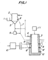
- Figure 1 illustrates one embodiment of this first aspect of the invention.
- Powdery or fine granular metal oxide is fed from a feeder 1 to a preliminary reducing furnace 2.
- a part or the whole of a gas, heated at a high temperature, which is discharged from a vertical melt-reducing furnace 3 through a gas outlet 4 is directly introduced into the preliminary reducing furnace 2 through a gas inlet 5 in the preliminary reducing furnace 2 and dries, heats and preliminarily reduces the metal oxide in the preliminary reducing furnace by a fluidized system.
- preliminarily reduced ore is discharged from an outlet 6 and blown into the vertical furnace 3 together with preheated air through a pipe 7 shown by a dotted line and tuyeres 8 and/or 8'.
- the heated air (referred to as "hot air” hereinafter) blown into the vertical furnace 3 is heated to 800-1,300°C in a gas heating furnace 10. Oxygen gas may be blown together with the hot air. Furthermore, a flux may be blown together with the preliminarily reduced ore into the vertical furnace 3 through the tuyere by the hot air in order to advantageously effect the melt-reducing refining.
- a carbonaceous solid reducing agent is fed into the vertical furnace 3 through a feeding device 11 to form a packed bed in the furnace 3 and raceways are formed in the furnace 3 due to the hot air in the vicinity of the tuyere tops in the same manner as in the vicinity of the tuyere top in a blast furnace and high temperature zones at 2,000-2,500°C are formed.
- the preliminarily reduced ore blown into these zones with the hot air or oxygen is immediately heated and easily melted.
- the melted ore is reduced whilst it drops down to a lower portion of the furnace 3 to form a molten metal and a molten slag and effect the refining.
- the refined metal is collected in the furnace bottom portion and timely discharged out of the furnace from a taphole 12.
- the circumference of the above described raceway portions forming the high temperature zones is bounded by the packed bed consisting of lump carbonaceous reducing agent and the gas at the circumference of the raceway portions is low in oxygen content, that is the oxygen partial pressure is low.
- the carbonaceous solid reducing agent use may be made of lump coke, lump char or coal, alone or in admixture.
- the height of the vertical furnace 3 may be less than that of a usual blast furnace and the preliminarily reduced ore is supplied into the furnace 3 from the tuyeres, so that a reducing agent having high strength, as in a blast furnace, is not needed. Hence expensive caking coal is not needed and this is commercially advantageous.
- the preliminarily reduced ore is once oxidized by oxygen in the hot air in the raceway portions and heated and melted due to the reaction heat.
- the reduction ratio is high and the use of the preliminarily reduced ore at a high temperature renders the melting easy and the present invention is advantageous in this respect.
- the preliminary reduction ratio is varied depending upon the kind of ore and the like but the best results can be obtained within the range of 40-80%.
- the preliminarily reduced ore is mainly fed from tuyeres 8 positioned at the upper stage and melted in the vicinity of the tuyere tops in the upper stage and the lower portion of the furnace is heated to a high temperature by tuyeres 8' in the lower stage to supply the heat energy necessary for reducing the molten ore dropping down from the vicinity of the tuyere tops 8 in the upper stage.
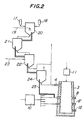
- Powdery or fine granular ore and a powdery flux are charged into the granulating device 20 from storage tanks 17 and 18 respectively and granulated through a fluidizing system while feeding water from a spray 19 to prepare mixed particles of the ore and the flux (referred to merely as "mixed particles” herinafter).
- the fluidizing gas used is the exhaust gas from the drier 21.
- the size of the particles is preferred to be less than 3 mm having regard to the subsequent steps of drying, firing and preliminary reduction and the need to transfer the particles between the respective steps.
- the green mixed particles produced in device 20 are then fluidized and dried in the drier 21.
- the drying temperature is lower than 200°C and the exhaust gas discharged from the firing furnace 22 in the next step may be utilized for the drying.
- the firing temperature is preferred to be up to 900°C since, if the temperature is higher than 900°C, the particles sinter and become bonded with one another. This hinders the flow of the particles from the firing furnace 22 and, further, the fluidizing of the particles stops.
- the heating source for the firing furnace use is made of the reaction heat obtained by burning a part of the gas discharged from the outlet 4 of the melt-reducing furnace 3 with air blown from an air blowing pipe 23.
- the fired mixed particles are transferred into the preliminary reducing furnace 24 and a part of the gas discharged from the outlet 4 of the furnace 3 is directly blown into the preliminary reducing furnace 24 from a lower portion thereof and the particles are fluidized and partially reduced.
- the gas discharged from the furnace 3 consists of CO, CO 2 , H 2 , H 2 0, N 2 and the like at a temperature of 600-1,500°C and the content of the reducing gases CO and H 2 is high.
- the preliminary reduction ratio of the preliminarily reduced particles increases and the temperature of the particles fed into the melt-reducing furnace 3 increases, the melting of the particles in the furnace 3 becomes easier.
- the above described preliminary reduction ratio varies depending upon the kind of ore but said ratio is preferred to be about 40-80%.
- the particles discharged from the preliminary reducing furnace 24 are charged into the melt-reducing furnace 3 through a feeding device 25 and mainly the tuyere 8.
- This feeding device 25 may be a mechanism wherein the preliminarily reduced particles are carried by a flow of N 2 or the gas evolved in the melt-reducing furnace.
- the melt-reduction in the melt-reducing furnace 3 occurs in the manner described with reference to Figure 1 but in order to make the refining reaction in the furnace 3 more smooth, it is possible to additionally add flux into the furnace 3, if necessary.
- the size of the particles granulated in the fluidizing granulating device is less than 3 mm, a gas carrying system can be used for transferring the particles between the respective steps, the amount of gas necessary for the fluidizing in the respective steps is small, and the reaction in the melt-reducing furnace proceeds quickly. Thus such a size is advantageous.
- the production system shown in Figure 2 has the following merits.
- the carbonaceous solid reducing agent is in powder form and is fed into a preliminary treating furnace.
- a part of the high temperature gas generated in the vertical melt-reducing furnace is introduced into the above described preliminary treating furnace and the above described reducing agent is subjected to a preliminary treatment in which said agent is dried and heated while fluidizing.
- the powdery ore is charged into the preliminary reducing furnace and a part of the gases generated in the vertical melt-reducing furnace and a part or the whole of the gases generated in the preliminary treating furnace are introduced into the preliminary reducing furnace and the powdery ore is reduced while being fluidized.
- a high temperature gas containing oxygen is fed into the vertical melt-reducing furnace through a plurality of tuyeres provided at a lower portion of the furnace.
- the preliminarily reduced ore prepared in the preliminary reducing furnace and the preliminarily treated reducing agent heated in the preliminary treating furnace, and if necessary a flux, are fed into the vertical melt-reducing furnace where the preliminarily treated reducing agent is burnt in a fluidized state and the preliminarily reduced ore is melt-reduced by the heat and the reducing gas generated by this burning to obtain a molten metal and a molten slag.
- the molten metal is discharged from the furnace floor to the outside of the furnace.
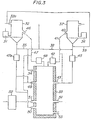
- Figure 3 illustrates an embodiment of this second aspect of the present invention.
- a powdery carbonaceous reducing agent is fed into a preliminary treating furnace 32 from a device 31 for feeding carbonaceous solid reducing agent and a part or the whole of the gas generated in a vertical melt-reducing furnace 33 is directly introduced into the preliminary treating furnace 32 through an outlet 34 and a pipe 35.
- the reducing agent is dried while being fluidized in the preliminary treating furnace 32 to effect a preliminary treatment in which the reducing agent is heated or carbonized to the necessary extent.
- the coal is subjected to carbonization through the preliminary treatment in the preliminary treating furnace 32 to form powdery coke or char which is discharged from the furnace 32.
- the powdery carbonaceous reducing agent may be directly fed into the vertical melt-reducing furnace 33 without using the preliminary treating furnace 32 but when carbonized gas containing hydrocarbons or tar is needed in the preliminary reducing furnace and other installations or when the reducing agent must be preheated in order to facilitate burning in the vertical melt-reducing furnace, it is particularly advantageous to preliminarily treat the reducing agent in the preliminary treating furnace 32.
- the powdery ore containing metal oxides is fed into a preliminary treating furnace 37 from an ore feeding device 36 and a part or the whole of the gas generated from the vertical melt-reducing furnace 33 and/or a part or the whole of the gas generated from the preliminary treating furnace 32 are directly fed into the furnace 37 through pipes 38 and 39 and the powdery ore is desired, heated and preliminarily reduced to the desired extent while being fluidized in the furnace 37.
- the gas generated in the vertical melt-reducing furnace 33 is discharged at a high temperature of 900-1,500 * C and includes N 2 , CO, CO z , H 2 , H 2 0 and the like and the content of the reducing gases CO and H 2 is high.
- the gas generated in the preliminary treating furnace 32 when coal is the starting material, includes N 2 , CO, CO 2 , H 2 , H 2 0, C n H m (meaning hydrocarbons) and the like and the content of the reducing gases CO, H 2 or C n H m is high.
- This gas is discharged at a temperature of 300-800°C from outlet 32a of the preliminary treating furnace 32. Accordingly, the powdery ore is preliminarily reduced while being fluidized in the preliminary reducing furnace 37.
- the preliminarily reduced ore is discharged in a highly heated condition from the preliminary reducing furnace 37 by means of a discharging device 40 and is tranferred to at least one of preliminarily reduced ore feeding devices 42 and 43, through a guide device 41, with a flux being added on the way if necessary, and charged into the vertical melt-reducing furnace 33.
- the preliminarily reduced ore is transferred with gas to the feeding device 43, which are in the form of tuyeres, and as the carrying gas, use is made of the gas generated from the vertical melt-reducing furnace 33 and, in some cases, it is advantageous to pressurize the carrying gas, by means of a pressurizing device 45, to facilitate the transfer of the preliminarily reduced ore.
- the carbonaceous reducing agent treated in the preliminary treating furnace 32 is discharged from an outlet 46 and is fed into the vertical melt-reducing furnace 33 through at least one of feeding devices 48, 49 and 50 via guide device 47.
- the reducing agent is transferred to feeding devices 49 and 50, which are in the form of tuyeres, by means of gas generated in the vertical melt-reducing furnace 33. This gas may be pressurized, if necessary, by means of pressurizing device 47a.
- the reducing agent is reacted with oxygen-containing gas having a high temperature, which is supplied from tuyeres 51 located below the upper tuyeres 43 and 49, and burnt therein, or contacted with metal oxides in the preliminarily reduced ore which has been fed into the vertical melt-reducing furnace 33 and melted therein whereby the metal oxide is reduced to form the metal.
- oxygen-containing gas having a high temperature use may be made of air or oxygen enriched air which is heated to a temperature of 800-1,300'C by means of a gas heating furnace 52, such as a hot air furnace.
- Powdery carbonaceous solid reducing agent or powdery carbonaceous solid reducing agent treated in the preliminary treating furnace is burnt with the oxygen-containing gas at a high temperature at an upper zone above the position of the top of the tuyere 50 in the furnace 33, to evolve a high temperature and thereby the preliminarily reduced ore is heated, melted and reduced in this high temperature zone to form a molten metal and a molten slag, which are collected in two layers at the lower portion of the vertical melt-reducing furnace 33.
- the molten metal is timely discharged out of the furnace from an outlet 53.
- carbonaceous solid reducing agent supplied to the preliminary treating furnace 32 use may be made of powdery coke, char and coal either alone or in admixture.
- powdery coke, char and coal either alone or in admixture.
- conventional inexpensive non-caking coal can be advantageously used and when lump coke is used, powdery coke prepared in the production of lump coke can be advantageously used.
- the preliminarily reduced powdery ore supplied to the vertical melt-reducing furnace 33 is quickly melted and reduced in the high temperature zone in the vertical melt-reducing furnace 33 so it is advantageous, because the melt-reduction can thereby be easily effected, that the preliminarily reduced ore fed into the vertical melt-reducing furnace 33 is preheated to a high temperature and reduced to a high reduction ratio.
- the optimum preheating temperature and preliminary reduction ratio naturally vary depending upon the kind of metal oxide, the state of the ore containing the metal oxide and the system used but good results can be obtained when the preheating temperature and the preliminary reduction ratio are about 400-1,000°C and 40-80% respectively.
- the oxygen-containing gas introduced through tuyeres 51 has a high temperature of 800-1,300°C and the furnace circumference around the inner end of the tuyere 50 is heated to a temperature of 2,000-2,500°C.
- the shape of the tuyere 51 may be made similar to the shape of the tuyere of an iron making blast furnace but in order to maintain the temperature of the molten metal pool on the furnace floor at 1,400-1,700°C, it is desirable that the inclined angle of the tuyere 51 projecting into the furnace is within a range of 40° downwardly from the horizontal so that the high temperature gas directly contacts the above described molten metal pool.
- the vertical melt-reducing furnace is divided into upper and lower zones by a perforated plate and the powdery ore is fed into the upper zone which serves as the preliminary reducing furnace.
- the upper and lower inlets of the melt-reducing furnace are in the form of tuyeres and are provided in the lower zone.
- a reducing gas formed in the lower zone rises into the upper zone through the perforated plate and the powdery ore is dried, heated and reduced while being fluidized with this gas to the necessary degree.
- the gas rising into the upper zone through the perforated plate may be all or a part of the gas generated, in the lower zone.
- reducing gas or an inert gas may be suplied to the lower zone below the perforated plate from the outside to control the fluidized state of the ore or the temperature, component composition and the like of the fluidizing gas in the upper zone.
- the gas generated in the lower zone includes N 2 , CO, CO 2 , H 2 , H 2 0, C m H n , etc. and, among these, the content of gases having a high reducibility, such as CO, H 2 , C m H n , etc. is high.
- the temperature of the gas is 600-1,200°C and this gas is introduced into the upper zone through the perforated plate.
- the ore which has been subjected to the fluidizing preliminary reduction in the upper zone overflows and is discharged at a high temperature from the upper zone through an outlet provided in the upper zone and blown, together with a flux and air or oxygen enriched air heated at a high temperature, into a bed of carbonaceous solid reducing agent through the upper of the inlets provided in the lower zone.
- the above described air or oxygen enriched air is heated at a temperature of 800-1,350°C in a gas heating furnace, such as a hot air furnace.
- Air or oxygen enriched air having a high temperature is blown also from the lower of the inlets into the lower zone.
- the carbonaceous solid reducing agent forming the packed bed is burnt and a high temperature is evolved, so that the above described blown preliminarily reduced ore is heated and melted and directly reduced by the carbonaceous solid reducing agent whilst dropping down in the packed bed to form a molten metal and a molten slag, which are collected at the bottom of the lower zone.
- the molten metal is timely discharged out of the vertical furnace.
- lump coke is preferably used but lump coal, char, charcoal, etc. may be used either alone or in combination.
- the height of the vertical melt-reducing furnace may be less than that of the usual iron making blast furnaces and it is not necessary to charge lump coke in alternate layers as the iron making blast furnace so that cokes having a high strength are not needed and hence expensive caking coal is not needed.
- the ore Unless the preliminarily reduced ore fed from the upper of the inlets is rapidly melted in the vicinity of the inlets, the ore cannot drop down to the bottom portion of the lower zone and this causes operating troubles. However these troubles can be prevented by blowing air of oxygen enriched air having a high temperature from the lower of the inlets in the lower zone.
- the preliminarily reduced ore blown from the upper of the inlets is oxidized by the oxygen and the heating and melting are promoted owing to the reaction heat. Accordingly, the melting becomes easier as the reduction ratio and preheating temperature of the preliminarily reduced ore increases.
- the optimum preliminary reduction ratio naturally varies according to the kind of ore and the system used but said ratio is preferred to be about 40-80%.
- An apparatus for refining a metal oxide in accordance with this third aspect of the present invention comprises a vertical melting and reducing furnace, said furnace being divided by a perforated plate into an upper zone for carrying out a preliminary reduction of said ore in the fluidized state and a lower zone for melting and reducing the preliminarily reduced ore to form a molten metal, a molten slag and a reducing gas which rises up to the upper zone to effect the preliminary reduction; said lower zone being provided with an inlet for feeding a carbonaceous solid reducing agent, upper and lower inlets for blowing therein air or oxygen enriched air heated at elevated temperature, and an outlet for discharging the molten metal and the molten slag; and said upper zone being provided with an inlet for feeding said ore therein, an outlet to enable the preliminarily reduced ore to overflow from the upper zone and enter the lower zone via the upper of the inlets, and an outlet for discharging the exhaust gas generated in the preliminary reduction.
- Figure 4 illustrates an embodiment of this third aspect of the present invention.
- a vertical melt-reducing furnace 81 divided by a perforated plate 83 into an upper zone and a lower zone.
- the upper zone serves as a preliminary reducing furnace and is provided with a feeding device 62 for powdery ore and a guide device in the form of pipes 58 by which the powdery ore preliminarily reduced in the upper zone can overflow and be discharged in the fluidized state from the upper zone to the lower zone which serves as the melt-reducing furnace proper.
- the upper zone also has a further outlet 60 for the exhaust gas after the fluidizing reduction has been effected. This is in a relatively higher part of the upper zone.
- a device 55 for controlling the reducing gas generated in the lower zone may be provided, if necessary.
- a feeding device 57 for feeding carbonaceous reducing agent to the lower zone is provided and the lower portion of this feeding device 57 in the upper zone is branched to form branched tubes 59 and these branched tubes 59 penetrate the perforated plate 83 and terminate in the lower zone to form inlets for the reducing agent.
- An outlet 61 for discharging molten metal and molten slag is provided at the bottom of the lower zone.
- Figure 5 is an explanatory sectional view of another embodiment of the third aspect of the present invention and parts corresponding to parts of Figure 4 are denoted by like reference numerals.
- the apparatus shown in Figure 5 is different from that in Figure 4 in that the carbonaceous reducing agent feeding device 57 does not penetrate the upper zone and the perforated plate 43. Rather it is located externally of the furnace so that it terminates at an inlet for the reducing agent and the reducing agent is directly fed to the lower zone from the outside of the furnace. Except for the feeding device 57, the other structure is quite the same as in Figure 4. According to the apparatus in Figure 4, the carbonaceous reducing agent fed through the feeding device 57 is preheated during its passage through the upper zone. This is thermally advantageous but the structure of the feeding device 57 becomes somewhat complicated and it is exposed to a high temperature so that its durability is less than in the apparatus shown in Figure 5. In Figure 5, the feeding device 57 is not exposed to high temperature, so that its durability is higher, but cold carbonaceous reducing agent is directly fed to the lower zone so that this apparatus is more thermally disadvantageous than that shown in Figure 4.
- the apparatus of these embodiments are characterised in that the tuyeres 56 and 54 are provided at an upper stage and a lower stage, respectively.
- a large heat energy is needed for melting and further reducing the preliminarily reduced ore and if the tuyeres 54 at the lower stage were not provided, even though the preliminarily reduced ore would be melted above the tuyere 56 at the upper stage, the zone below the tuyere 56 of the upper stage would be low in temperature and thus the reduction of the molten ore by the carbonaceous solid reducing agent would not be satisfactorily effected and the operation could not be continued due to the cooling down of the furnace.
- the cooling down of the lower portion of the furnace can be completely prevented since air or oxygen-enriched air at high temperature is introduced into the furnace through the tuyeres 54 at the lower stage to burn the carbonaceous reducing agent at the lower portion of the furnace.
- the refining process is characterised in that a carbonization of the carbonaceous solid reducing agent is carried out during the first preliminary reducing step, whereby the exhaust gas and char which are the reaction products are used as a valuable recovered product and a reducing agent in the next melt-reducing step, respectively and the heat source is substantially supplied by a circulating gas obtained in the process of the invention itself.
- this aspect lies in a method for melting and refining metal oxides in which the metal oxides are subjected to a preliminary reduction through a fluidizing reaction in the preliminary reducing furnace and the preliminarily reduced metal oxide is melt-reduced in the melt-reducing furnace wherein the preliminary reducing furnace is divided into an upper portion and a lower portion by a perforated plate, powdered carbonaceous solid reducing agent, metal oxides and a flux are charged into the upper portion, and a circulating reducing gas having a high temperature generated in this upper portion itself is fed into the lower portion of the furnace whereby a carbonization reaction of the carbonaceous reducing agent and a preliminary reduction of the metal oxide is effected to produce mixed particles of char, flux and metal oxide.
- the mixed particles prepared in the preliminary reducing furnace are introduced into the melt-reducing furnace via the upper of the inlets and are subjected to melt-reduction as a consequence of a combustion reaction caused between the above described char and a combustion supporting gas fed into the melt-reducing furnace to produce molten metal and molten slag.
- the gas generated in the upper portion of the preliminary reducing furnace is separated by means of a separator into tar and a hydrocarbon-containing fuel gas and said fuel gas is circulated and introduced, together with the high temperature gas generated in the melt-reducing furnace, into the preliminary reducing furnace.
- An apparatus for refining a metal oxide in accordance with this fourth aspect of the invention comprises an apparatus for use in melting and refining a powdery or fine granular ore containing metal oxide which apparatus comprises (a) a preliminary reducing furnace divided by a perforated plate into an upper portion wherein carbonaceous solid reducing agent is carbonized to form char and said ore is preheated and preliminarily reduced and a lower portion wherein the preliminarily reduced ore, char and a flux are mixed, and (b) a vertical melting and reducing furnace wherein the preliminarily reduced mixed particles are melted and reduced through a combustion-fluidizing reaction with air or oxygen enriched air at elevated temperature to form molten metal and molten slag, said melting and reducing furnace having upper and lower inlets, a pipe being provided to convey said preliminary reduced mixed particles to the upper of the inlets; and a means being provided to introduce said air or oxygen enriched air via the lower of the inlets.
- Figure 6 illustrates the dry-refining of metal oxides in accordance with this fourth aspect of the present invention.
- A is a carbonizing and preliminarily reducing furnace, which is divided into an upper chamber A, and a lower chamber A 2 by a perforated plate 79.
- powdery carbonaceous reducing agent such as coal
- metal oxide ore is charged from an inlet 63
- reaction additives such as a flux for the metal oxide and a desulfurizing agent for the carbonaceous reducing agent, are charged from an inlet 64.
- a reducing gas having a high temperature mentioned hereinafter is introduced into the lower chamber A z of the carbonizing and preliminary reducing furnace via inlet 68.
- the reducing gas having a high temperature rises through the perforated plate 79, said gas contacts with the powdery carbonaceous reducing agent, metal oxide and additives and fluidizes these substances at a temperature range of 500 ⁇ 700°C which is suitable for the carbonization of the carbonaceous reducing agent.
- the carbonaceous reducing agent such as a coal which is very easily caked, is mixed and quickly heated within a given temperature range and the carbonization reaction proceeds smoothly.
- the carbonization of the carbonaceous reducing agent effectively occurs at about 500°C and the reaction efficiency is reduced at temperatures lower than 500°C.
- the carbonization can be effected at a reaction temperature higher than 700°C but the tar components of the carbonaceous reducing agent then volatilize and become gaseous so that, in order to effectively recover tar in a liquid state by a separator, the temperature is preferred to be lower than 700°C. If the reaction temperature becomes higher than 700°C, the liquid tar component is decomposed and the conversion rate into hydrocarbon gas increases.
- the volatile matter in the carbonaceous reducing agent when the carbonization is effected within the above described temperature range, evolves as a carbonized gas containing tar, hydrogen, methane and the like and this gas is taken out from an outlet 65 in the upper chamber A, and the liquid tar is separated and recovered in a separator 66 and the exhaust gas remaining is recovered through a purifying apparatus 67 including a desulfurizing apparatus.
- the recovered gas contains H 2 , CO, C m H n and the like and can be effectivley utilized as a clean fuel gas, a reducing gas for ore, or a starting gas to be used in chemical industry. Of course, this gas can also be utilized as a source for heating air to a high temperature, which is supplied to the hereinafter mentioned melt-reducing furnace.
- the recovered tar is subjected to another purifying treatment and is used as a starting material in the chemical industry.
- steam may be added to the reaction in the above described furnace.
- the residue i.e. char obtained in the carbonization of coal
- the residue moves down to the lower chamber A 2 together with the flux and the metal oxide ore which has been preheated and preliminarily reduced while being fluidized with reducing gas and carbonised gas fed into furnace A via inlet 68.
- This preliminarily reduced metal oxide ore has a catalytic function with respect to the carbonization reaction of the carbonaceous reducing agent, such as coal, and the carbonization reaction smoothly proceeds at a high yield.
- Sulfur in the carbonaceous reducing agent transfers into the carbonized gas during the reaction in the carbonizing-preliminary reducing furnace, so that a powdery desulfurizing agent, such as lime, is supplied as an additive and by this means, sulfur in the carbonized gas is very effectively absorbed and therefore the role of the purifying apparatus 66 for treating the generated gas can be reduced.
- a powdery desulfurizing agent such as lime
- Lime used as the desulfurizing agent in the reaction in the carbonizing-preliminary reducing furnace A may be effectively used as a component of the flux which renders the melting of the metal oxides easy.
- the lime has a plurality of functions, one of which is to act as a flux which desulfurizes the exhaust carbonized gas in the upper chamber A, and makes the melting in the hereinafter mentioned vertical melt-reducing furnace B easy, and another of which is to catch sulfur in the char as a slag.
- the present invention is very effective as a method for utilizing lime.
- the metal oxide ore, the carbonaceous reducing agent and the additives are concurrently fluidized within a temperature of 500-700°C.
- the powdery product having a temperature of 500-700°C formed in the carbonizing-preliminary reducing furnace A includes char, the preliminarily reduced metal oxide and the additives and is transferred into the lower chamber A 2 through the above described perforated separating plate 79.
- the gas introduced into the lower chamber A 2 for the preliminary reduction is a mixed gas having a high temperature consisting of carbon monoxide, mainly from the exhaust gas having a high temperature generated in the melt-reducing furnace B, and H 2 and C m H n from the exhaust gas from the upper chamber A, of the carbonizing-preliminary reducing furnace A and the preliminary reduction of metal oxides proceeds, due to the strong reducing action of these substances, to a higher extent than does the reduction in the upper chamber and, for example, the reduction ratio reaches 40-80% according to the kind of metal oxide.
- the reaction in the lower chamber A 2 utilises, in combination, the recovery of the sensible heat of the exhaust gas from the melt-reducing furnace B and the reducing ability of the exhaust gas from the upper chamber A,.
- the preliminarily reduced and preheated metal oxide, the flux and the char are thoroughly mixed and fed into the melt-reducing furnace B through an inlet 69, a pipe 70 and an upper inlet 71 for the preliminarily reduced product.
- a controlling device 72 such as a valve, for controlling the fed amount and said device is regulated according to the progress of the melt-reducing reaction.
- the char preheated at 800-1,200°C which is transferred to the melt-reducing furnace B from the inlet 71 for the preliminarily reduced product is burnt by reaction with a combustion supporting gas, such as air heated to 800-1,300°C by being passed through an air heater 73 using exhaust gas obtained from the upper chamber A, as a heating source, and which is introduced from a tuyere 74 provided at the lower portion of the furnace whereby a fluidized bed of char having a high temperature of higher than 1,500°C is formed.
- a combustion supporting gas such as air heated to 800-1,300°C by being passed through an air heater 73 using exhaust gas obtained from the upper chamber A, as a heating source, and which is introduced from a tuyere 74 provided at the lower portion of the furnace whereby a fluidized bed of char having a high temperature of higher than 1,500°C is formed.
- air specifically prepared by adding oxygen having a high purity may be used instead of air.
- the powdery metal oxide fed through the inlet 71 which has been preheated to a temperature of 80G-1,200 0 C and preliminarily reduced to a reduction ratio of 40-80%, is instantaneously melted together with a very satisfactorily mixed powdery flux and is quickly and concurrently reduced by the char having a high temperature or by the carbon monoxide formed by the fluid-combustion of the char.
- molten metal and slag are formed and collected in the lower portion of the melt-reducing furnace B as shown by M and S in Figure 6.
- the molten metal and slag are discharged through outlets 75 and 76. According to the progress of the reaction in the melt-reducing furnace B, for example when a large amount of char is mixed in the collected slag, the reaction can be promoted by supplementing oxygen having a high purity or feeding a flux.
- the gas generated by the fluid-combustion of char in the melt-reducing furnace B and the melt-reduction of the preliminarily reduced metal oxide is discharged through an outlet 77 but as mentioned above, a part or the whole of said gas is introduced into the above described carbonizing-preliminary reducing furnace A and the remainder is delivered to an exhaust gas treating device 78 including an exhaust heat recovering device and treated therein.
- the gas generated in the furnace B consists mainly of CO and N 2 and is effective as a part of the heat source of the air heater and further is valuable as a fuel gas and a starting gas for chemical industry.
- Examples 1 and 2 concern the first aspect of the present invention.
- low caking or non-caking coals having a relatively low cost can be used without using expensive electric power and caking coals, and the reducing gas discharged from the melt-reducing furnace can be effectively used for the preliminary reduction of the ore.
- This aspect of the present invention is expected to be used as an advantageous method for refining metal oxides.
- the Example concerns the second aspect of the present invention and was carried out by following the method described with reference to Figure 3.
- iron ore was used but other ores such as nickel ore, manganese ore, and chromium ore may be used as the starting material for carrying out the present invention.
Landscapes
- Engineering & Computer Science (AREA)
- Chemical & Material Sciences (AREA)
- Manufacturing & Machinery (AREA)
- Materials Engineering (AREA)
- Metallurgy (AREA)
- Organic Chemistry (AREA)
- Manufacture And Refinement Of Metals (AREA)
- Manufacture Of Iron (AREA)
Claims (13)
Applications Claiming Priority (8)
| Application Number | Priority Date | Filing Date | Title |
|---|---|---|---|
| JP63294/81 | 1981-04-28 | ||
| JP56063294A JPS5918452B2 (ja) | 1981-04-28 | 1981-04-28 | 粉粒状鉱石からの溶融金属製造方法 |
| JP6811081A JPS5918453B2 (ja) | 1981-05-08 | 1981-05-08 | 金属酸化物を含有する粉状鉱石からの溶触金属製造法 |
| JP68110/81 | 1981-05-08 | ||
| JP7563981A JPS57192783A (en) | 1981-05-21 | 1981-05-21 | Method of melting and smelting powdered metal ore and its melting smelting device |
| JP75639/81 | 1981-05-21 | ||
| JP56111357A JPS5928605B2 (ja) | 1981-07-16 | 1981-07-16 | 金属酸化物の製錬方法およびその装置 |
| JP111357/81 | 1981-07-16 |
Publications (4)
| Publication Number | Publication Date |
|---|---|
| EP0063924A2 EP0063924A2 (de) | 1982-11-03 |
| EP0063924A3 EP0063924A3 (en) | 1983-02-09 |
| EP0063924B1 EP0063924B1 (de) | 1986-10-29 |
| EP0063924B2 true EP0063924B2 (de) | 1990-03-14 |
Family
ID=27464289
Family Applications (1)
| Application Number | Title | Priority Date | Filing Date |
|---|---|---|---|
| EP82302056A Expired - Lifetime EP0063924B2 (de) | 1981-04-28 | 1982-04-22 | Verfahren und Vorrichtung zum Schmelzen und Frischen von feinverteiltem metalloxydhaltigem Erz |
Country Status (4)
| Country | Link |
|---|---|
| US (1) | US4874427A (de) |
| EP (1) | EP0063924B2 (de) |
| DE (1) | DE3273996D1 (de) |
| PH (1) | PH21317A (de) |
Families Citing this family (60)
| Publication number | Priority date | Publication date | Assignee | Title |
|---|---|---|---|---|
| GB2103249B (en) * | 1981-06-23 | 1986-07-23 | Yoshida Iron Works Co Ltd | Method of producing castings using reduced iron as raw material, melting furnace and briquette used as raw material for castings |
| AT378970B (de) * | 1982-12-21 | 1985-10-25 | Voest Alpine Ag | Verfahren und vorrichtung zur herstellung von flùssigem roheisen oder stahlvorprodukten |
| AT382165B (de) * | 1983-08-18 | 1987-01-26 | Voest Alpine Ag | Verfahren zur herstellung von fluessigem roheisen oder stahlvorprodukten sowie vorrichtung zur durchfuehrung des verfahrens |
| AT388388B (de) * | 1983-11-24 | 1989-06-12 | Voest Alpine Ag | Verfahren und vorrichtung zum schmelzen von eisen in einem einschmelzvergaser |
| IN164687B (de) * | 1984-08-16 | 1989-05-13 | Voest Alpine Ag | |
| JPH079015B2 (ja) * | 1985-07-19 | 1995-02-01 | 株式会社神戸製鋼所 | 鉄鉱石の溶融還元方法 |
| US4685964A (en) * | 1985-10-03 | 1987-08-11 | Midrex International B.V. Rotterdam | Method and apparatus for producing molten iron using coal |
| DE3535572A1 (de) * | 1985-10-03 | 1987-04-16 | Korf Engineering Gmbh | Verfahren zur herstellung von roheisen aus feinerz |
| BR8605001A (pt) * | 1986-10-13 | 1988-05-31 | Setepla Tecnometal Engenharia | Equipamento para producao de metais ferrosos ou nao a partir de minerios ou aglomerados auto-redutores e auto-fundentes ou nao |
| US5064174A (en) * | 1989-10-16 | 1991-11-12 | Northern States Power Company | Apparatus for production of energy and iron materials, including steel |
| US5045112A (en) * | 1988-02-08 | 1991-09-03 | Northern States Power Company | Cogeneration process for production of energy and iron materials, including steel |
| US5055131A (en) * | 1987-08-31 | 1991-10-08 | Northern States Power Company | Cogeneration process for production of energy and iron materials |
| US5066325A (en) * | 1987-08-31 | 1991-11-19 | Northern States Power Company | Cogeneration process for production of energy and iron materials, including steel |
| US4940488C2 (en) * | 1987-12-07 | 2002-06-18 | Kawasaki Heavy Ind Ltd | Method of smelting reduction of ores containing metal oxides |
| FI84841C (sv) * | 1988-03-30 | 1992-01-27 | Ahlstroem Oy | Förfarande och anordning för reduktion av metalloxidhaltigt material |
| DE4108283A1 (de) * | 1991-03-14 | 1992-09-17 | Kortec Ag | Verfahren zum herstellen von fluessigem metall aus feinkoernigen metalloxidpartikeln und reduktions- und schmelzofen zur durchfuehrung des verfahrens |
| DE4216891A1 (de) * | 1992-05-21 | 1993-11-25 | Kortec Ag Zug | Verfahren und Einrichtung zum Erhitzen und Schmelzen von stückigem Eisenschwamm |
| US5320676A (en) * | 1992-10-06 | 1994-06-14 | Bechtel Group, Inc. | Low slag iron making process with injecting coolant |
| US5397376A (en) * | 1992-10-06 | 1995-03-14 | Bechtel Group, Inc. | Method of providing fuel for an iron making process |
| US6197088B1 (en) | 1992-10-06 | 2001-03-06 | Bechtel Group, Inc. | Producing liquid iron having a low sulfur content |
| US5338336A (en) * | 1993-06-30 | 1994-08-16 | Bechtel Group, Inc. | Method of processing electric arc furnace dust and providing fuel for an iron making process |
| US5380352A (en) * | 1992-10-06 | 1995-01-10 | Bechtel Group, Inc. | Method of using rubber tires in an iron making process |
| US5259864A (en) * | 1992-10-06 | 1993-11-09 | Bechtel Group, Inc. | Method of disposing of environmentally undesirable material and providing fuel for an iron making process e.g. petroleum coke |
| US5354356A (en) * | 1992-10-06 | 1994-10-11 | Bechtel Group Inc. | Method of providing fuel for an iron making process |
| US5429658A (en) * | 1992-10-06 | 1995-07-04 | Bechtel Group, Inc. | Method of making iron from oily steel and iron ferrous waste |
| AT404735B (de) * | 1992-10-22 | 1999-02-25 | Voest Alpine Ind Anlagen | Verfahren und anlage zur herstellung von flüssigem roheisen oder flüssigen stahlvorprodukten |
| GB9325418D0 (en) * | 1993-12-13 | 1994-02-16 | Boc Group Plc | Method and apparatus for producing iron |
| US5958107A (en) * | 1993-12-15 | 1999-09-28 | Bechtel Croup, Inc. | Shift conversion for the preparation of reducing gas |
| AUPN226095A0 (en) | 1995-04-07 | 1995-05-04 | Technological Resources Pty Limited | A method of producing metals and metal alloys |
| DE19634348A1 (de) | 1996-08-23 | 1998-02-26 | Arcmet Tech Gmbh | Einschmelzaggregat mit einem Lichtbogenofen |
| US5810905A (en) * | 1996-10-07 | 1998-09-22 | Cleveland Cliffs Iron Company | Process for making pig iron |
| AT405651B (de) * | 1996-10-08 | 1999-10-25 | Voest Alpine Ind Anlagen | Vorrichtung zum dosierten einbringen von feinteilchenförmigem material in ein reaktorgefäss |
| AUPO426396A0 (en) | 1996-12-18 | 1997-01-23 | Technological Resources Pty Limited | A method of producing iron |
| AUPO426096A0 (en) | 1996-12-18 | 1997-01-23 | Technological Resources Pty Limited | Method and apparatus for producing metals and metal alloys |
| AUPO944697A0 (en) * | 1997-09-26 | 1997-10-16 | Technological Resources Pty Limited | A method of producing metals and metal alloys |
| AUPP442598A0 (en) | 1998-07-01 | 1998-07-23 | Technological Resources Pty Limited | Direct smelting vessel |
| AUPP483898A0 (en) | 1998-07-24 | 1998-08-13 | Technological Resources Pty Limited | A direct smelting process & apparatus |
| MY119760A (en) | 1998-07-24 | 2005-07-29 | Tech Resources Pty Ltd | A direct smelting process |
| AUPP554098A0 (en) | 1998-08-28 | 1998-09-17 | Technological Resources Pty Limited | A process and an apparatus for producing metals and metal alloys |
| AUPP570098A0 (en) | 1998-09-04 | 1998-10-01 | Technological Resources Pty Limited | A direct smelting process |
| AUPP647198A0 (en) | 1998-10-14 | 1998-11-05 | Technological Resources Pty Limited | A process and an apparatus for producing metals and metal alloys |
| LU90333B1 (fr) * | 1998-12-23 | 2000-07-19 | Wurth Paul Sa | Proc-d- d'optimisation du fonctionnement d'un four - cuve |
| AUPP805599A0 (en) | 1999-01-08 | 1999-02-04 | Technological Resources Pty Limited | A direct smelting process |
| AUPQ083599A0 (en) | 1999-06-08 | 1999-07-01 | Technological Resources Pty Limited | Direct smelting vessel |
| AUPQ152299A0 (en) | 1999-07-09 | 1999-08-05 | Technological Resources Pty Limited | Start-up procedure for direct smelting process |
| AUPQ205799A0 (en) | 1999-08-05 | 1999-08-26 | Technological Resources Pty Limited | A direct smelting process |
| AUPQ213099A0 (en) | 1999-08-10 | 1999-09-02 | Technological Resources Pty Limited | Pressure control |
| AUPQ308799A0 (en) | 1999-09-27 | 1999-10-21 | Technological Resources Pty Limited | A direct smelting process |
| AUPQ346399A0 (en) | 1999-10-15 | 1999-11-11 | Technological Resources Pty Limited | Stable idle procedure |
| AUPQ365799A0 (en) | 1999-10-26 | 1999-11-18 | Technological Resources Pty Limited | A direct smelting apparatus and process |
| US6602321B2 (en) | 2000-09-26 | 2003-08-05 | Technological Resources Pty. Ltd. | Direct smelting process |
| RU2344107C1 (ru) * | 2007-04-23 | 2009-01-20 | Общество с ограниченной ответственностью "Адакта" | Способ твердофазного синтеза оксидных материалов и установка непрерывного синтеза для его реализации |
| CN100500873C (zh) * | 2007-09-12 | 2009-06-17 | 钢铁研究总院 | 熔融还原快速预还原细微铁矿粉的方法 |
| CN102417993B (zh) * | 2011-08-08 | 2013-05-29 | 新鑫矿业股份有限公司喀拉通克铜镍矿 | 一种富氧侧吹熔池熔炼开炉新方法 |
| RU2489255C1 (ru) * | 2011-11-25 | 2013-08-10 | Общество с ограниченной ответственностью "Электродные материалы для литий-ионных технологий" (ООО "ЭЛИОНТ") | Автоматизированная технологическая линия для непрерывного производства твердофазных композиционных материалов на основе сложных оксидов |
| CN108913914B (zh) * | 2018-09-21 | 2024-03-12 | 中国恩菲工程技术有限公司 | 铜熔炼装置 |
| EP3647459A1 (de) * | 2018-10-31 | 2020-05-06 | Petroceramics S.p.A. | Verfahren und anordnung durch chemische gasphaseninfiltration von porösen komponenten |
| CN109492296B (zh) * | 2018-11-06 | 2023-04-07 | 首钢集团有限公司 | 一种用于表征干熄焦炉透气性的方法及系统 |
| NL2023109B1 (en) * | 2019-05-10 | 2020-11-30 | African Rainbow Minerals Ltd | Process for the smelting of a metalliferous feedstock material |
| CN110408795B (zh) * | 2019-08-19 | 2021-05-18 | 江苏宏航机械有限公司 | 一种红土镍矿侧吹炉冶炼镍铁设备 |
Family Cites Families (18)
| Publication number | Priority date | Publication date | Assignee | Title |
|---|---|---|---|---|
| DE1024245B (de) * | 1952-12-16 | 1958-02-13 | Ruhrgas Ag | Verfahren zur Verhuettung staubfoermiger oder feinkoerniger Erze mit staubfoermigen oder feinkoernigen Brennstoffen |
| DE1122564B (de) * | 1953-08-18 | 1962-01-25 | Werner Wenzel Dr Ing | Verfahren zur Eisengewinnung aus in der Schwebe befindlichen, staubfoermigen bzw. feinkoernigen Eisenerzen mittels Brennstoffen in feinem Verteilungsgrad oberhalb des Schmelzpunktes der nicht gasfoermigen Reaktionsprodukte |
| FR1218464A (fr) * | 1957-11-04 | 1960-05-11 | Procédé de traitement des minerais de fer | |
| FR1243733A (fr) * | 1959-01-01 | 1960-10-14 | British Iron Steel Research | Procédé de réduction des minerais métallifères, en particulier des minerais de fer pour la production du fer |
| US3028231A (en) * | 1959-01-01 | 1962-04-03 | British Iron Steel Research | Processing of metallic ores |
| US3145094A (en) * | 1959-09-12 | 1964-08-18 | Nakajima Toitsu | Process and apparatus for making steel from powdered iron ore |
| FR1414716A (fr) * | 1961-02-27 | 1965-10-22 | Inst Francais Du Petrole | Nouveau procédé continu de réduction des minerais de fer |
| US3936296A (en) * | 1970-02-25 | 1976-02-03 | Campbell Donald L | Integrated fluidized reduction and melting of iron ores |
| DE2132150B2 (de) * | 1971-06-29 | 1980-07-24 | Wasmuht, Jobst-Thomas, Dr.-Ing., 4600 Dortmund | Verfahren zum direkten Herstellen von Stahl |
| SE388210B (sv) * | 1973-01-26 | 1976-09-27 | Skf Svenska Kullagerfab Ab | Sett vid reduktion av metall ur metalloxider |
| DE2401909C3 (de) * | 1974-01-16 | 1985-06-27 | Fried. Krupp Gmbh, 4300 Essen | Verfahren zur Herstellung von Stahl |
| IT1038230B (it) * | 1974-05-22 | 1979-11-20 | Krupp Gmbh | Procedimento per la produzione di acciaio |
| DK288176A (da) * | 1975-07-04 | 1977-01-05 | Boliden Ab | Fremgangsmade til fremstilling af et delvis forreduceret produkt |
| DE2843303C2 (de) * | 1978-10-04 | 1982-12-16 | Korf-Stahl Ag, 7570 Baden-Baden | Verfahren und Anlage zur Erzeugung von flüssigem Roheisen und Reduktionsgas in einem Einschmelzvergaser |
| US4212452A (en) * | 1979-04-30 | 1980-07-15 | Jack Hsieh | Apparatus for the direct reduction of iron ore |
| US4270740A (en) * | 1979-07-16 | 1981-06-02 | Midrex Corporation | Apparatus for producing molten iron by submerged combustion |
| DE3034539C2 (de) * | 1980-09-12 | 1982-07-22 | Korf-Stahl Ag, 7570 Baden-Baden | Verfahren und Vorrichtung zur direkten Erzeugung von flüssigem Roheisen aus stückigem Eisenerz |
| SE457265B (sv) * | 1981-06-10 | 1988-12-12 | Sumitomo Metal Ind | Foerfarande och anlaeggning foer framstaellning av tackjaern |
-
1982
- 1982-04-22 DE DE8282302056T patent/DE3273996D1/de not_active Expired
- 1982-04-22 EP EP82302056A patent/EP0063924B2/de not_active Expired - Lifetime
- 1982-04-26 PH PH27194A patent/PH21317A/en unknown
-
1987
- 1987-12-02 US US07/127,600 patent/US4874427A/en not_active Expired - Fee Related
Also Published As
| Publication number | Publication date |
|---|---|
| US4874427A (en) | 1989-10-17 |
| EP0063924B1 (de) | 1986-10-29 |
| EP0063924A3 (en) | 1983-02-09 |
| DE3273996D1 (en) | 1986-12-04 |
| EP0063924A2 (de) | 1982-11-03 |
| PH21317A (en) | 1987-09-28 |
Similar Documents
| Publication | Publication Date | Title |
|---|---|---|
| EP0063924B2 (de) | Verfahren und Vorrichtung zum Schmelzen und Frischen von feinverteiltem metalloxydhaltigem Erz | |
| CA1050765A (en) | Method for making steel | |
| SU1674694A3 (ru) | Способ получени расплавленных железосодержащих материалов из тонкоизмельченной руды и устройство дл его осуществлени | |
| US6270553B1 (en) | Direct reduction of metal oxide agglomerates | |
| US4045214A (en) | Method for producing steel | |
| KR930004475B1 (ko) | 금속 산화물을 함유한 물질의 환원방법 및 장치 | |
| US5613997A (en) | Metallurgical process | |
| EP0864658B1 (de) | Reduktion von Eisenerz | |
| KR20090034386A (ko) | 금속함유 재료를 환원 생성물로 환원시키는 방법 및 장치 | |
| US3206299A (en) | Dense-bed, rotary, kiln process and apparatus for pretreatment of a metallurgical charge | |
| JPS6254163B2 (de) | ||
| US20050092130A1 (en) | Process and apparatus for the direct reduction of iron oxides in an electrothermal fluidized bed and resultant product | |
| GB2189504A (en) | Process and apparatus for gasification | |
| CN1312860A (zh) | 制造液态生铁的工艺方法 | |
| US6395057B1 (en) | Method for producing directly reduced iron in a layered furnace | |
| US4416689A (en) | Process for the manufacture of crude iron and energy-rich gases | |
| US5810905A (en) | Process for making pig iron | |
| SU1582991A3 (ru) | Способ получени металлов и сплавов и установка дл его осуществлени | |
| MXPA97007698A (en) | Procedure to make arra | |
| US3832158A (en) | Process for producing metal from metal oxide pellets in a cupola type vessel | |
| JPH037723B2 (de) | ||
| JPS6156255A (ja) | 非鉄金属鉱石または精鉱からの金属回収精錬方法 | |
| CN1545562A (zh) | 在竖炉中具有挥发性再生金属回收功能的还原熔炼方法 | |
| JPS63216934A (ja) | クロム鉱石等の流動層環元方法 | |
| JPS5928605B2 (ja) | 金属酸化物の製錬方法およびその装置 |
Legal Events
| Date | Code | Title | Description |
|---|---|---|---|
| PUAI | Public reference made under article 153(3) epc to a published international application that has entered the european phase |
Free format text: ORIGINAL CODE: 0009012 |
|
| AK | Designated contracting states |
Designated state(s): DE FR GB SE |
|
| PUAL | Search report despatched |
Free format text: ORIGINAL CODE: 0009013 |
|
| AK | Designated contracting states |
Designated state(s): DE FR GB SE |
|
| 17P | Request for examination filed |
Effective date: 19830411 |
|
| GRAA | (expected) grant |
Free format text: ORIGINAL CODE: 0009210 |
|
| AK | Designated contracting states |
Kind code of ref document: B1 Designated state(s): DE FR GB SE |
|
| REF | Corresponds to: |
Ref document number: 3273996 Country of ref document: DE Date of ref document: 19861204 |
|
| ET | Fr: translation filed | ||
| PLBI | Opposition filed |
Free format text: ORIGINAL CODE: 0009260 |
|
| 26 | Opposition filed |
Opponent name: KORF ENGINEERING GMBH Effective date: 19870728 |
|
| PLAB | Opposition data, opponent's data or that of the opponent's representative modified |
Free format text: ORIGINAL CODE: 0009299OPPO |
|
| R26 | Opposition filed (corrected) |
Opponent name: KORF ENGINEERING GMBH Effective date: 19870728 |
|
| PUAH | Patent maintained in amended form |
Free format text: ORIGINAL CODE: 0009272 |
|
| STAA | Information on the status of an ep patent application or granted ep patent |
Free format text: STATUS: PATENT MAINTAINED AS AMENDED |
|
| 27A | Patent maintained in amended form |
Effective date: 19900314 |
|
| AK | Designated contracting states |
Kind code of ref document: B2 Designated state(s): DE FR GB SE |
|
| ET3 | Fr: translation filed ** decision concerning opposition | ||
| EAL | Se: european patent in force in sweden |
Ref document number: 82302056.5 |
|
| PGFP | Annual fee paid to national office [announced via postgrant information from national office to epo] |
Ref country code: SE Payment date: 19990406 Year of fee payment: 18 |
|
| PGFP | Annual fee paid to national office [announced via postgrant information from national office to epo] |
Ref country code: FR Payment date: 19990409 Year of fee payment: 18 |
|
| PGFP | Annual fee paid to national office [announced via postgrant information from national office to epo] |
Ref country code: GB Payment date: 19990421 Year of fee payment: 18 |
|
| PGFP | Annual fee paid to national office [announced via postgrant information from national office to epo] |
Ref country code: DE Payment date: 19990430 Year of fee payment: 18 |
|
| PG25 | Lapsed in a contracting state [announced via postgrant information from national office to epo] |
Ref country code: GB Free format text: LAPSE BECAUSE OF NON-PAYMENT OF DUE FEES Effective date: 20000422 |
|
| PG25 | Lapsed in a contracting state [announced via postgrant information from national office to epo] |
Ref country code: SE Free format text: LAPSE BECAUSE OF NON-PAYMENT OF DUE FEES Effective date: 20000423 |
|
| EUG | Se: european patent has lapsed |
Ref document number: 82302056.5 |
|
| GBPC | Gb: european patent ceased through non-payment of renewal fee |
Effective date: 20000422 |
|
| PG25 | Lapsed in a contracting state [announced via postgrant information from national office to epo] |
Ref country code: FR Free format text: LAPSE BECAUSE OF NON-PAYMENT OF DUE FEES Effective date: 20001229 |
|
| PG25 | Lapsed in a contracting state [announced via postgrant information from national office to epo] |
Ref country code: DE Free format text: LAPSE BECAUSE OF NON-PAYMENT OF DUE FEES Effective date: 20010201 |
|
| REG | Reference to a national code |
Ref country code: FR Ref legal event code: ST |