EP0063841A2 - Wärmebildgerät - Google Patents
Wärmebildgerät Download PDFInfo
- Publication number
- EP0063841A2 EP0063841A2 EP82200453A EP82200453A EP0063841A2 EP 0063841 A2 EP0063841 A2 EP 0063841A2 EP 82200453 A EP82200453 A EP 82200453A EP 82200453 A EP82200453 A EP 82200453A EP 0063841 A2 EP0063841 A2 EP 0063841A2
- Authority
- EP
- European Patent Office
- Prior art keywords
- scene
- array
- detectors
- imaging apparatus
- thermal imaging
- Prior art date
- Legal status (The legal status is an assumption and is not a legal conclusion. Google has not performed a legal analysis and makes no representation as to the accuracy of the status listed.)
- Withdrawn
Links
Images
Classifications
-
- H—ELECTRICITY
- H04—ELECTRIC COMMUNICATION TECHNIQUE
- H04N—PICTORIAL COMMUNICATION, e.g. TELEVISION
- H04N23/00—Cameras or camera modules comprising electronic image sensors; Control thereof
- H04N23/20—Cameras or camera modules comprising electronic image sensors; Control thereof for generating image signals from infrared radiation only
- H04N23/23—Cameras or camera modules comprising electronic image sensors; Control thereof for generating image signals from infrared radiation only from thermal infrared radiation
Definitions
- This invention relates to imaging apparatus in which an image of a scene is formed in non-visible radiation from the scene and in which a radiation detector is scanned across the image, a visible version of the scene being reconstructed by a corresponding scan of a light source modulated by the detector output. More particularly it relates to thermal imaging apparatus in which the non-visible radiation is the natural thermal infra-red radiation emitted by objects in the scene by reason of their temperatures and emissivities.
- a thermal imaging apparatus is disclosed in U.S. Patent Specification 3,626,091 comprising a linear array of infra-red detectors and a corresponding linear array of light sources modulated one each by the detector outputs and synchronously scanned in a plurality of bands of lines across the scene by a rotating mirror prism having planar mirrors set at various angles around the axis of rotation, the mirror prism having twice as many mirror faces as there are bands scanned in the scene. Scanning is carried out by one set of mirrors while reconstruction is carried out by a second set of mirrors.
- British Patent Specification 2,087,189A describes thermal imaging apparatus of this type in which a mirror prism is used in which all but one of the planar mirrors take part in both scanning and reconstruction.
- the detectors commonly photoconductive indium antimonide or cadmium mercury telluride,. are usually cooled and usually have a cold shield to limit their field of view. Liquid nitrogen, solid carbon dioxide or thermo-electric cooling means may be employed. In consequence, the radiation emitted by the detectors themselves, by the substrate upon which they are mounted and by the cold shield will be generally less than that emitted by adjacent uncooled parts of the inside of the apparatus.
- An objective lens is used to form an infra-red image of the scene upon-the detectors. Typically, this objective will be stationary relative to the detectors and the planar scanning mirrors are beyond the objective. An a-focal telescope may be placed beyond the scanning mirrors to provide telefoto or wide-angle viewing.
- an a-focal refracting telescope may be used comprising germanium and silicon elements as is described and claimed in British Patent Specification No. 1,530,066.
- the optical elements of this telescope frequently comprise surfaces concave towards the detectors.
- Germanium and silicon are of relatively high refractive index, 3.4. and 4.0 respectively, and the amplitude of thermal radiation reflected by such surfaces is not negligible, even when these surfaces have been bloomed to minimise such reflection.
- the detectors receive reflected radiation emitted by themselves, the substrate, and the cold shield by reflection in at least one surface of the objective elements or, via the scanning mirror, in at least one surface of the telescope elements, which radiation is reduced in amount compared to that which they receive during the remainder of the scan from adjacent uncooled parts of the inside of the apparatus.
- the general level of the detector outputs falls during the centre part of the scan, darkening the general level of picture detail and creating the appearance of a dark patch in the centre of the picture.
- this is known as the "narcissus" effect, referring to the fact that it is due to the cooled detectors "seeing" themselves by reflection.
- thermal imager is being used to view a generally cold scene, a considerable drop in detector output occurs as the scanning mirror passes from the inside of the equipment onto the scene.
- An object of the invention is to provide thermal imaging apparatus in which the narcissus effect is suppressed.
- the invention is characterised in that there is provided a summing device for forming a signal derived from the sum of all electrical output signals of the detectors, the output signal of said summing device being added to each of the detector output signals in negative feedback.
- a common method of displaying the reconstructed version of the visible scene is by also using the scanning mirrors to scan light sources modulated by corresponding detectors.
- the invention may also provide thermal imaging apparatus characterised in that said scanning means comprise a mirror prism which is rotatable about an axis and which includes a plurality of planar mirrors which form an equiangular polygon in a cross section normal to said axis and which make a sequence of various tilt angles with said axis so that said scene is scanned two-dimensionally as the mirror prism is rotated about said axis, the objective lens being arranged to receive infra-red radiation from said scene via said planar mirrors as they pass through a scanning location and to form an image of said scene which, in response to prism rotation, moves transversely across said array of infra-red radiation detectors, and in that said display means comprise a linear array of light sources coupled one each to a corresponding detector in said detector array, each light source being adapted to produce a light beam modulated in response to
- the benefit of the invention will be obtained generally when the picture detail shows a steady periodic type of temperature variation across the frame, when the lines of the band differ from one another and when there are a relatively large number of detectors in the array so that the sum signal contains little of the detail of any one line and represents an average of scene brightness variation across the picture.
- the sum signal applied in the negative feedback will operate to suppress low frequency temperature contours in the scene and low frequency signals derived from the contrast between the equipment interior and the scene.
- the invention may also be characterised in that a low-pass filter is connected in said negative feedback connection between the source of said sum signal and said detectors, whereby relatively high frequency picture detail is substantially not reduced by said negative feedback.
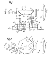
- Figures 1 and 2 show schematic elevation and plan views respectively of a thermal imaging apparatus employing modulated light sources for picture reconstruction and display.
- Figures 1 and 2 the chief ray 8 of a beam of infra-red radiation is shown entering the apparatus from a point in the scene in the centre of the field of view.
- An afocal Galilean telescope 9 may be employed to provide scene magnification by a factor of between 2 and 3.
- the telescope comprises a'positive silicon lens 7 and a negative germanium lens 6 as described in British Patent Specification No. 1,530,066.
- the beam of infra-red radiation is reflected by a planar mirror 3 of a rotatable mirror prism 1 to be substantially parallel to the axis of rotation 2 of said mirror prism.
- An objective lens 4 at the scanning location forms an image 10 of the scene in the plane of a linear array of infra-red detectors 5 aligned along a radius extending from the axis of rotation 2.
- the detectors 5 are mounted on a 3-stage thermoelectric cooler 44.
- Rotation 11 of the prism about axis 2 causes the image 10 to be moved transversely across the length of the linear array 5, scanning a band of lines in the image 10.
- the rotational motion of mirror 3 also causes rotation of the image 10 in its own plane by an angle equal to the scan angle. Over the limited angle of rotation effectively used by mirror 3 for scanning, the scene distortion produced is relatively minor and is largely compensated by a corresponding rotation produced by image reconstruction using another mirror 3.
- the mirror prism 1 has nine planar mirrors 3 set at equal angles about the axis 2 so that any cross-section of the prism normal to axis 2 shows an equiangular polygon and, in particular, the section through the centres of mirrors 3 shows the regular polygon of Figure 2.
- the mirrors 3 are generally set at an angle of 45 degrees to axis 2, though each mirror 3 has a small additional angle of tilt away from 45 degrees different for each mirror 3.
- the difference in tilt angle between any two mirrors 3 is an integral multiple of half the angular length of the linear array 5 given by dividing the linear length of the array by the focal length of the objective lens 4.
- the image 10 is shifted along the array 5 by the length of the array so that the bands in the image 10 scanned by these two mirrors are contiguous.
- the sequence of mirror angles is given by the following table.
- a linear array of light sources 12, aligned along a radius extending from the axis of rotation 2, is provided at a reconstruction location coupled one each by an amplifier 40 to a corresponding detector in the detector array 5.
- Each light source produces a light output modulated in response to the radiation received by the corresponding detector.
- Lens 13 collimates light beams from the sources substantially parallel to axis 2 and directs them onto the face of a mirror 3.
- Lens 13 also presents the array 12 to the viewing optics at an angular length equal to that of the array 5 so that the reconstructed visible bands are contiguous.
- the reconstruction location is off-set in angle from the apparatus axis 14 by an angle of 20 degrees so that as one mirror 3 passes through the scanning location another mirror 3 passes through the reconstruction location synchronously.
- a pair of prisms 15 and 16 are used. These, by providing three reflections of the visible image in the horizontal plane, reverse the visible picture from left to right. The sequence of mirror tilt angles given in the above table results in the reconstructed picture being reversed top to bottom. Consequently there is one complete inversion of the visible image due to these two effects.
- Eyepiece lens 20 restores the overall magnification to unity and provides eye dioptre adjustment.
- Lens elements 6 and 7 of the telescope 9 have plane or concave surfaces towards mirrors 3 and detectors 5.
- the motion of mirrors 3 effectively swing the axis of telescope 9 through the axis of objective 4.
- the detectors will be exposed to reflected out-of-focus radiation from the cooled detector substrate of thermoelectric cooler 44 rather than to radiation from ambient temperature objects (not shown) either side of cooler 44.
- the general level of radiation at the detectors will fall, producing the "narcissus" effect in the reconstructed image.
- the general level.-of radiation at the detectors will rise if the scene is cooler than the equipment due to out-of-focus reflections from telescope clamp rings and internal imager components. This will add to.the "narcissus" effect and may even be the largest factor affecting image quality.
- the outputs 45 of the three adding amplifiers 40 are connected to the three inputs of a summing device comprising an inverting adder 41, the scaled output 43 of which is connected, optionally via a low-pass filter 42, to a second input of each of the adding amplifiers 40.
- the detectors may, for example, be photoconductive cells, each fed with a steady bias current from the common bias supply S via an individual load resistor R. The variations in infra-red radiation falling on each detector produce variations in its resistance and hence in its bias current.
- the output signal is taken across each detector and fed via a pre-amplifier 47 to the first inputs of amplifiers 40. Between the detectors and the light sources, the amplifiers are a.c. coupled.
- the effect of the invention is also to increase the dynamic range of brightness which can be displayed and to produce a picture of a more even appearance. Infra-red scenes frequently contain detail superimposed on both extended cold areas and extended hot areas and the invention assists in displaying both sets of detail in one picture. Also, in battery powered equipment, the current taken by the light sources 12, which are typically light-emitting diodes may be an appreciable fraction of the total current. Without the invention, excessive current may be carried by the diodes in extended light areas. Thus, the invention is of value in reducing battery drain.
Landscapes
- Health & Medical Sciences (AREA)
- Toxicology (AREA)
- Engineering & Computer Science (AREA)
- Multimedia (AREA)
- Signal Processing (AREA)
- Transforming Light Signals Into Electric Signals (AREA)
- Radiation Pyrometers (AREA)
- Mechanical Optical Scanning Systems (AREA)
Applications Claiming Priority (2)
| Application Number | Priority Date | Filing Date | Title |
|---|---|---|---|
| GB8113286 | 1981-04-29 | ||
| GB8113286A GB2097627B (en) | 1981-04-29 | 1981-04-29 | Thermal imaging apparatus |
Publications (2)
| Publication Number | Publication Date |
|---|---|
| EP0063841A2 true EP0063841A2 (de) | 1982-11-03 |
| EP0063841A3 EP0063841A3 (de) | 1983-05-25 |
Family
ID=10521492
Family Applications (1)
| Application Number | Title | Priority Date | Filing Date |
|---|---|---|---|
| EP82200453A Withdrawn EP0063841A3 (de) | 1981-04-29 | 1982-04-14 | Wärmebildgerät |
Country Status (4)
| Country | Link |
|---|---|
| US (1) | US4450479A (de) |
| EP (1) | EP0063841A3 (de) |
| JP (1) | JPS57197514A (de) |
| GB (1) | GB2097627B (de) |
Cited By (1)
| Publication number | Priority date | Publication date | Assignee | Title |
|---|---|---|---|---|
| GB2307125A (en) * | 1989-03-21 | 1997-05-14 | British Aerospace | Optical equipment |
Families Citing this family (12)
| Publication number | Priority date | Publication date | Assignee | Title |
|---|---|---|---|---|
| US4692618A (en) * | 1985-05-02 | 1987-09-08 | Hughes Aircraft Company | Detector signal conditioner |
| FR2586487B1 (fr) * | 1985-08-20 | 1987-11-20 | Thomson Csf | Dispositif d'autoalignement pour systeme optique d'observation d'images infrarouges |
| US4682029A (en) * | 1985-10-22 | 1987-07-21 | Magnavox Government And Industrial Electronics Company | Stereoscopic infrared imager having a time-shared detector array |
| US4705945A (en) * | 1986-01-31 | 1987-11-10 | Barnes Engineering Company | Narcissus correction for infrared scanning microscope |
| GB2200813B (en) * | 1987-02-03 | 1991-06-05 | Gec Avionics | Thermal imager |
| US4968898A (en) * | 1987-10-12 | 1990-11-06 | Jeol Ltd. | Pulse shaping circuit for radiation detector |
| GB2268353B (en) * | 1992-06-22 | 1996-02-14 | Marconi Gec Ltd | Imaging apparatus |
| US5446284A (en) * | 1994-01-25 | 1995-08-29 | Loral Infrared & Imaging Systems, Inc. | Monolithic detector array apparatus |
| JP4558964B2 (ja) * | 2001-02-23 | 2010-10-06 | リコー光学株式会社 | 光走査方法および装置および画像形成装置 |
| US6631287B2 (en) | 2001-04-03 | 2003-10-07 | Welch Allyn, Inc. | Infrared thermometer |
| US9307912B2 (en) | 2012-08-08 | 2016-04-12 | Welch Allyn, Inc. | Temperature measurement system |
| CN109829861B (zh) * | 2018-12-29 | 2020-08-11 | 西安电子科技大学 | 一种基于小波分解的冷反射抑制方法 |
Family Cites Families (9)
| Publication number | Priority date | Publication date | Assignee | Title |
|---|---|---|---|---|
| US3626091A (en) * | 1969-12-11 | 1971-12-07 | Hughes Aircraft Co | Image converter |
| US4222065A (en) * | 1975-08-02 | 1980-09-09 | Gunter Pusch | Method and apparatus for scanning and for electronic processing of thermal pictures |
| DE2534586C3 (de) * | 1975-08-02 | 1979-03-29 | Pusch, Guenter, Dr.-Ing., 6903 Neckargemuend | Verfahren und Einrichtung zur Abtastung und zur elektronischen Verarbeitung thermischer Bilder |
| JPS54161227A (en) * | 1978-06-12 | 1979-12-20 | Mitsubishi Electric Corp | Infrared-ray pickup unit |
| DE2848325A1 (de) * | 1978-11-08 | 1980-05-22 | Philips Patentverwaltung | Waermebildgeraet zum erfassen und erkennen eines waermeziels |
| JPS55126211A (en) * | 1979-03-20 | 1980-09-29 | Mitsubishi Electric Corp | Image pickup device |
| US4225883A (en) * | 1979-06-11 | 1980-09-30 | The United States Of America As Represented By The Secretary Of The Army | Automatic responsivity compensator in an IR imaging system |
| US4338627A (en) * | 1980-04-28 | 1982-07-06 | International Telephone And Telegraph Corporation | LED/CCD Multiplexer and infrared image converter |
| FR2492616A1 (fr) * | 1980-10-17 | 1982-04-23 | Thomson Csf | Dispositif opto-electronique d'analyse d'images video-frequence par balayage rotatif |
-
1981
- 1981-04-29 GB GB8113286A patent/GB2097627B/en not_active Expired
-
1982
- 1982-04-14 EP EP82200453A patent/EP0063841A3/de not_active Withdrawn
- 1982-04-15 US US06/368,782 patent/US4450479A/en not_active Expired - Fee Related
- 1982-04-26 JP JP57070175A patent/JPS57197514A/ja active Pending
Cited By (2)
| Publication number | Priority date | Publication date | Assignee | Title |
|---|---|---|---|---|
| GB2307125A (en) * | 1989-03-21 | 1997-05-14 | British Aerospace | Optical equipment |
| GB2307125B (en) * | 1989-03-21 | 1998-01-07 | British Aerospace | Adaptive Background Compensation Circuit For Optical Imaging Equipment |
Also Published As
| Publication number | Publication date |
|---|---|
| EP0063841A3 (de) | 1983-05-25 |
| JPS57197514A (en) | 1982-12-03 |
| GB2097627B (en) | 1985-02-13 |
| GB2097627A (en) | 1982-11-03 |
| US4450479A (en) | 1984-05-22 |
Similar Documents
| Publication | Publication Date | Title |
|---|---|---|
| US3670097A (en) | Stereoscopic television system and apparatus | |
| US10061130B2 (en) | Wide-field of view (FOV) imaging devices with active foveation capability | |
| US6266194B1 (en) | Picture display apparatus and camera | |
| US4574197A (en) | Dual field of view sensor | |
| US4450479A (en) | Thermal imaging apparatus | |
| DE69829907T2 (de) | Ein optisches Spiegelsystem | |
| US5229880A (en) | Three field of view refractive afocal telescope | |
| US20100277595A1 (en) | Clip-on infrared imager | |
| US9122039B2 (en) | Compact internal field of view switch and pupil relay | |
| US4682029A (en) | Stereoscopic infrared imager having a time-shared detector array | |
| IL263544A (en) | Optical configurations for optical field mappings for back-scanned and line-scanned imagers | |
| US4475039A (en) | Infrared viewing apparatus | |
| US3972584A (en) | Compound optical system with image tilt compensation | |
| EP0468045A1 (de) | Infrarot bildformungssystem mit gleichzeitig aenderbarem gesichtsfeld und aufloesung sowie fester optischer vergroesserung. | |
| EP0051894B1 (de) | Abbildungsgerät | |
| US6252565B1 (en) | Elliptical cavity optical retinal display | |
| US6181486B1 (en) | Optical architecture for infrared viewing system | |
| US4106845A (en) | Infra-red scanner | |
| US5650869A (en) | Point relay scanner utilizing ellipsoidal mirrors | |
| CA2140681C (en) | Wide area coverage infrared search system | |
| Mansuripur | The Shack-Hartmann Wavefront Sensor | |
| GB2037119A (en) | Reducing the effect of defective elements in a thermal image detector array | |
| EP0052395A1 (de) | Abbildungsgerät | |
| KR102825291B1 (ko) | 영상 복합 관측경 | |
| US20230168475A1 (en) | Anti-blur infrared lens for panoramic camera system using hd resolution sensor |
Legal Events
| Date | Code | Title | Description |
|---|---|---|---|
| PUAI | Public reference made under article 153(3) epc to a published international application that has entered the european phase |
Free format text: ORIGINAL CODE: 0009012 |
|
| 17P | Request for examination filed |
Effective date: 19820414 |
|
| AK | Designated contracting states |
Designated state(s): DE FR GB NL SE |
|
| PUAL | Search report despatched |
Free format text: ORIGINAL CODE: 0009013 |
|
| AK | Designated contracting states |
Designated state(s): DE FR GB NL SE |
|
| STAA | Information on the status of an ep patent application or granted ep patent |
Free format text: STATUS: THE APPLICATION IS DEEMED TO BE WITHDRAWN |
|
| 18D | Application deemed to be withdrawn |
Effective date: 19840302 |
|
| RIN1 | Information on inventor provided before grant (corrected) |
Inventor name: HORNE, DAVID ROBERT |