EP0063788A2 - Dispositif de réglage d'écoulement d'un conduit d'admission de forme hélicoidale - Google Patents
Dispositif de réglage d'écoulement d'un conduit d'admission de forme hélicoidale Download PDFInfo
- Publication number
- EP0063788A2 EP0063788A2 EP82103382A EP82103382A EP0063788A2 EP 0063788 A2 EP0063788 A2 EP 0063788A2 EP 82103382 A EP82103382 A EP 82103382A EP 82103382 A EP82103382 A EP 82103382A EP 0063788 A2 EP0063788 A2 EP 0063788A2
- Authority
- EP
- European Patent Office
- Prior art keywords
- valve
- vacuum
- intake port
- bypass passage
- vacuum chamber
- Prior art date
- Legal status (The legal status is an assumption and is not a legal conclusion. Google has not performed a legal analysis and makes no representation as to the accuracy of the status listed.)
- Granted
Links
Images

Classifications
-
- F—MECHANICAL ENGINEERING; LIGHTING; HEATING; WEAPONS; BLASTING
- F02—COMBUSTION ENGINES; HOT-GAS OR COMBUSTION-PRODUCT ENGINE PLANTS
- F02F—CYLINDERS, PISTONS OR CASINGS, FOR COMBUSTION ENGINES; ARRANGEMENTS OF SEALINGS IN COMBUSTION ENGINES
- F02F1/00—Cylinders; Cylinder heads
- F02F1/24—Cylinder heads
- F02F1/42—Shape or arrangement of intake or exhaust channels in cylinder heads
- F02F1/4228—Helically-shaped channels
-
- F—MECHANICAL ENGINEERING; LIGHTING; HEATING; WEAPONS; BLASTING
- F02—COMBUSTION ENGINES; HOT-GAS OR COMBUSTION-PRODUCT ENGINE PLANTS
- F02B—INTERNAL-COMBUSTION PISTON ENGINES; COMBUSTION ENGINES IN GENERAL
- F02B31/00—Modifying induction systems for imparting a rotation to the charge in the cylinder
- F02B31/04—Modifying induction systems for imparting a rotation to the charge in the cylinder by means within the induction channel, e.g. deflectors
- F02B31/06—Movable means, e.g. butterfly valves
- F02B31/08—Movable means, e.g. butterfly valves having multiple air inlets, i.e. having main and auxiliary intake passages
- F02B31/082—Movable means, e.g. butterfly valves having multiple air inlets, i.e. having main and auxiliary intake passages the main passage having a helical shape around the intake valve axis; Engines characterised by provision of driven charging or scavenging pumps
-
- F—MECHANICAL ENGINEERING; LIGHTING; HEATING; WEAPONS; BLASTING
- F02—COMBUSTION ENGINES; HOT-GAS OR COMBUSTION-PRODUCT ENGINE PLANTS
- F02B—INTERNAL-COMBUSTION PISTON ENGINES; COMBUSTION ENGINES IN GENERAL
- F02B1/00—Engines characterised by fuel-air mixture compression
- F02B1/02—Engines characterised by fuel-air mixture compression with positive ignition
- F02B1/04—Engines characterised by fuel-air mixture compression with positive ignition with fuel-air mixture admission into cylinder
-
- F—MECHANICAL ENGINEERING; LIGHTING; HEATING; WEAPONS; BLASTING
- F02—COMBUSTION ENGINES; HOT-GAS OR COMBUSTION-PRODUCT ENGINE PLANTS
- F02F—CYLINDERS, PISTONS OR CASINGS, FOR COMBUSTION ENGINES; ARRANGEMENTS OF SEALINGS IN COMBUSTION ENGINES
- F02F1/00—Cylinders; Cylinder heads
- F02F1/24—Cylinder heads
- F02F2001/244—Arrangement of valve stems in cylinder heads
- F02F2001/245—Arrangement of valve stems in cylinder heads the valve stems being orientated at an angle with the cylinder axis
-
- Y—GENERAL TAGGING OF NEW TECHNOLOGICAL DEVELOPMENTS; GENERAL TAGGING OF CROSS-SECTIONAL TECHNOLOGIES SPANNING OVER SEVERAL SECTIONS OF THE IPC; TECHNICAL SUBJECTS COVERED BY FORMER USPC CROSS-REFERENCE ART COLLECTIONS [XRACs] AND DIGESTS
- Y02—TECHNOLOGIES OR APPLICATIONS FOR MITIGATION OR ADAPTATION AGAINST CLIMATE CHANGE
- Y02T—CLIMATE CHANGE MITIGATION TECHNOLOGIES RELATED TO TRANSPORTATION
- Y02T10/00—Road transport of goods or passengers
- Y02T10/10—Internal combustion engine [ICE] based vehicles
- Y02T10/12—Improving ICE efficiencies
Definitions
- the present invention relates to a flow control device of a helically-shaped intake port of an internal combustion engine.
- a helically-shaped intake port normally comprises a helical portion formed around the intake valve of an engine, and a substantially straight inlet passage portion tangentially connected to the helical portion.
- a helically-shaped intake port is so formed that a strong swirl motion is created in the combustion chamber of an engine when the engine is operating at a low speed under a light load, that is, when the amount of air fed into the cylinder of the engine is small, since air flowing within the helically-shaped intake port is subjected to a great flow resistance, a problem occurs in that the volumetric efficiency is reduced when the engine is operating at a high speed under a heavy load, that is, when the amount of air fed into the cylinder of the engine is large.
- An object of the present invention is to provide a helically-shaped intake port capable of creating a strong swirl motion in the combustion chamber when the amount of air fed into the cylinder is small, while preventing the volumetric efficiency from being reduced when the engine is operating at a high speed under a heavy load.
- a device for controlling the flow in a helically-shaped intake port of an internal combustion engine comprising a helical portion formed around an intake valve, and a substantially straight inlet passage portion tangentially connected to the helical portion and having a helix terminating portion
- said device comprising: a bypass passage branched off from the inlet passage portion and connected to the helix terminating portion of the helical portion; a normally closed rotary valve arranged in said bypass passage for controlling the flow area of said bypass passage, and; actuating means for actuating said rotary valve in response to the change in the amount of air fed into the intake port to open said rotary valve when said amount of air is increased beyond a predetermined value.
- a cylindrical projection 11, projecting downwardly for supporting a valve guide 10 is formed in one piece on the upper inner wall of the helically-shaped intake port 6, and the tip of the valve guide 10 projects from the tip of the cylindrical projection 11.
- the mixture formed in the carburetor (not shown) is introduced into the combustion chamber 4 via the helically-shaped intake port 6 and the intake valve 5 and, then, the mixture is ignited by the spark plug 9 at the end of the compression stroke.
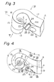
- Figs. 3 through 6 schematically illustrate the shape of the helically-shaped intake port 6 illustrated in Fig. 1.
- the helically-shaped intake port 6 comprises an inlet passage portion A and a helical portion B, the longitudinal central axis of the inlet passage portion A being slightly curved.
- the inlet open end of the inlet passage portion A has a rectangular cross-section, as illustrated in Fig. 7, and the mixture outlet portion 13 of the helical portion B has a cylindrical inner wall which extends circumferentially about the helix axis b of the helical portion B.
- Fig. 4 schematically illustrate the shape of the helically-shaped intake port 6 illustrated in Fig. 1.
- the helically-shaped intake port 6 comprises an inlet passage portion A and a helical portion B, the longitudinal central axis of the inlet passage portion A being slightly curved.
- the inlet open end of the inlet passage portion A has a rectangular cross-section, as illustrated in Fig. 7, and the mixture
- the helix axis b that is, the axis of the intake valve 5, is slightly inclined with respect to the axis of the cylinder, and the inlet passage portion A extends substantially horizontally.
- the side wall 14 of the inlet passage portion A which is located remote from the helix axis b, is arranged so as to be substantially vertical and is smoothly connected to the side wall 15 of the helical portion B, which extends circumferentially about the helix axis b.
- the side wall 15 of the helical portion B is so formed that it expands outwards from the cylindrical inner wall of the mixture outlet portion 13.
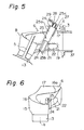
- Fig. 6 and 9 the side wall 15 of the helical portion B is so formed that it expands outwards from the cylindrical inner wall of the mixture outlet portion 13.
- the side wall 15 is so formed that the distance R between the side wall 15 and the helix axis b is maintained constant at a position near the inlet passage portion A and is gradually reduced towards the helical direction C.
- the distance R becomes approximately equal to the radius of the cylindrical inner wall of the mixture outlet portion 13 at the helix terminating portion E.
- the side wall 16 of the inlet passage portion A which is located near the helix axis b, has on its upper portion an inclined wall portion 16a which is arranged to be directed downwards.
- the width of the inclined wall portion 16a is gradually increased towards the helical portion B and, as is illustrated in Fig. 8, the entire portion of the side wall 16 is inclined at the connecting portion of the inlet passage portion A and the helical portion B.
- the upper half of the side wall 16 is smoothly connected to the circumferential wall of the cylindrical projection 11, and the lower half of the side wall 16 is connected to the side wall 15 of the helical portion B at the helix terminating portion E of the helical portion B.
- the upper wall 17 of the inlet passage portion A extends substantially horizontally from the inlet open end of the inlet passage portion A towards the helical portion B, and the upper wall 18 gradually descends towards the helical direction C (Fig. 4) and is connected to the side wall 16 of the inlet passage portion A. Since the inclined wall portion 16a of the inlet passage portion A is so formed that the width thereof is gradually increased towards the helical portion B, as mentioned above, the width of the upper wall 17 of the inlet passage portion A is gradually reduced.
- the width of the upper wall 18 of the helical portion B is gradually reduced towards the helical direction C. Consequently, it will be understood that the upper wall 17 of the inlet passage portion A extends substantially horizontally towards the helical portion B, while the width of the upper wall 17 is gradually reduced, and; that the upper wall 18 of the helical portion B gradually descends towards the helical direction C, while the width of the upper wall 18 is gradually reduced. As illustrated in Figs. 3, 4 and 9, the upper wall 18 is connected to a steeply inclined wall F arranged to be directed downwards at the helix terminating portion E.
- the bottom wall 19 of the inlet passage portion A extends substantially horizontally in parallel with the upper wall 17 towards the helical portion B and is connected to the cylindrical inner wall of the mixture outlet portion 13 via a smoothly curved wall 20 as illustrated in Fig. 1. From Fig. 4, it will be understood that the width of the bottom wall 19 is gradually reduced towards the helical portion B.
- the inlet opening 22 of the bypass passage 21 is formed on the side wall 16 at a position located near the inlet open end of the inlet passage portion A, and the outlet opening 23 of the bypass passage 21 is formed on the upper end portion of the side wall 15 at the helix terminating portion E. It is required that the bypass passage 21 have a cross-sectional area which is larger than 0.3 times the minimum cross--sectional area of the intake port 6. As illustrated in Fig.
- a cylindrical bore 24, extending across the bypass passage 21, is formed in the cylinder head 3, and a rotary valve 25 is inserted into the cylindrical bore 24.
- the rotary valve 25 comprises a cylindrical portion 25a, a plate-shaped valve portion 25b extending through the bypass passage 21, and a reduced diameter projecting portion 25c projecting from the top face of the cylindrical portion 25a.
- the cylindrical portion 25a is rotatably supported by a hollow sleeve 26 which is fixed onto the cylinder head 3.
- a torsion coil spring 28 is arranged between the reduced diameter projecting portion 25c of the rotary valve 25 and a projecting arm 27 of the hollow sleeve 26, so that the rotary valve 25 is always biased towards the closed position by means of the coil spring 28. As illustrated in Figs.
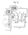
- an arm 29 is fixed onto the reduced diameter projecting portion 25c of the rotary valve 25, and the tip of the arm 29 is connected via a connecting rod 33 to a control rod 32 which is fixed onto a diaphragm 31 of a vacuum operated diaphragm apparatus 30.
- the diaphragm apparatus 30 comprises a vacuum chamber 34 separated from the atmosphere by the diaphragm 31, and a compression spring 35 for biasing the diaphragm 31 is inserted into the vacuum chamber 34.
- An intake manifold 37 equipped with a compound type carburetor 36 comprising a primary carburetor A and a secondary carburetor B, is mounted on the cylinder head 3, and the vacuum chamber 34 is connected to the interior of the intake manifold 37 via a vacuum conduit 38.
- a check valve 39 permitting air to flow from the vacuum chamber 34 into the intake manifold 37, is arranged in the vacuum conduit 38.
- the vacuum chamber 34 is connected to the atmosphere via an atmosphere conduit 40 and a control valve 41.
- This control valve 41 comprises a vacuum chamber 43 and an atmospheric pressure chamber 44 which are separated by a diaphragm 42 and, in addition, the control valve 41 further comprises a valve chamber 45 arranged adjacent to the atmospheric pressure chamber 44.
- the valve chamber 45 is connected, on one hand, to the vacuum chamber 34 via the atmosphere conduit 40 and, on the other hand, to the atmosphere via a valve port 46 and an air filter 47.
- a valve body 48 controlling the opening operation of the valve port 46, is arranged in the valve chamber 45 and connected to the diaphragm 42 via a valve rod 49.
- a compression spring 50 for biasing the diaphragm 42 is inserted into the vacuum chamber 43, and the vacuum chamber 43 is connected to a venturi portion 52 of the primary carburetor A via a vacuum conduit 51.
- the carburetor 36 is a conventional carburetor. Consequently, when the opening degree of a primary throttle valve 53 is increased beyond a predetermined degree, a secondary throttle valve 54 is opened and, when the primary throttle valve 53 is fully opened, the secondary throttle valve 54 is also fully opened.
- the level of vacuum produced in the venturi portion 52 of the primary carburetor A is increased as the amount of air fed into the cylinder of the engine is increased. Consequently, when a great vacuum is produced in the venturi portion 52, that is, when the engine is operating at a high speed under a heavy load, the diaphragm 42 of the control valve 41 moves towards the right in Fig. 10 against the compression spring 50.
- valve body 48 opens the valve port 46 and, thus, the vacuum chamber 34 of the diaphragm apparatus 30 becomes open to the atmosphere.
- the diaphragm 31 moves downward in Fig. 10 due to the spring force of the compression spring 35 and, thus, the rotary valve 25 is rotated and fully opens the bypass passage 21.
- the check valve 39 opens when the level of vacuum produced in the intake manifold 37 becomes greater than that of the vacuum produced in the vacuum chamber 34, and since the check valve 39 closes when the level of the vacuum produced in the intake manifold 37 becomes smaller than that of the vacuum produced in the vacuum chamber 34, the level of the vacuum in the vacuum chamber 34 is maintained at the maximum vacuum which has been produced in the intake manifold 37 as long as the control valve 41 remains closed. If a vacuum is produced in the vacuum chamber 34, the diaphragm 31 moves upward in Fig. 10 against the compression spring 35 and, as a result, the rotary valve 25 is rotated and closes the bypass passage 21. Consequently, when the engine is operating at a low speed under a light load, the bypass passage 21 is closed by the rotary valve 25.
- the rotary valve 25 closes the bypass passage 21.
- a part of the mixture introduced into the inlet passage portion A moves forward along the upper walls 17 and 18, as illustrated by the arrow K in Fig. 1, and the remaining part of the mixture impinges upon the inclined wall portion 16a and is deflected downwards.
- the remaining part of the mixture flows into the mixture outlet portion 13 without swirling, as illustrated by the arrow L in Fig. 1.
- the present invention it is possible to create a strong swirl motion in the combustion chamber when an engine is operating at a low speed under a light load, while ensuring a high volumetric efficiency when an engine is operating at a high speed under a heavy load by forming the bypass passage, the opening operation of which is controlled by the rotary valve.
Applications Claiming Priority (2)
| Application Number | Priority Date | Filing Date | Title |
|---|---|---|---|
| JP56061424A JPS57176320A (en) | 1981-04-24 | 1981-04-24 | Flow path controller for helical suction port |
| JP61424/81 | 1981-04-24 |
Publications (3)
| Publication Number | Publication Date |
|---|---|
| EP0063788A2 true EP0063788A2 (fr) | 1982-11-03 |
| EP0063788A3 EP0063788A3 (en) | 1983-04-13 |
| EP0063788B1 EP0063788B1 (fr) | 1985-03-20 |
Family
ID=13170681
Family Applications (1)
| Application Number | Title | Priority Date | Filing Date |
|---|---|---|---|
| EP82103382A Expired EP0063788B1 (fr) | 1981-04-24 | 1982-04-21 | Dispositif de réglage d'écoulement d'un conduit d'admission de forme hélicoidale |
Country Status (6)
| Country | Link |
|---|---|
| US (1) | US4466394A (fr) |
| EP (1) | EP0063788B1 (fr) |
| JP (1) | JPS57176320A (fr) |
| AU (1) | AU531472B2 (fr) |
| CA (1) | CA1208089A (fr) |
| DE (1) | DE3262608D1 (fr) |
Cited By (6)
| Publication number | Priority date | Publication date | Assignee | Title |
|---|---|---|---|---|
| EP0071179A2 (fr) * | 1981-07-31 | 1983-02-09 | Toyota Jidosha Kabushiki Kaisha | Dispositif de réglage d'un courant pour un canal d'admission de forme hélicoidale |
| EP0071272A2 (fr) * | 1981-07-30 | 1983-02-09 | Toyota Jidosha Kabushiki Kaisha | Dispositif de commande d'écoulement pour ouverture d'admission hélicoidale d'un moteur diesel |
| EP0094084A2 (fr) * | 1982-05-11 | 1983-11-16 | Toyota Jidosha Kabushiki Kaisha | Lumière d'aspiration hélicoidale pour un moteur à combustion interne |
| EP0102453A1 (fr) * | 1982-09-08 | 1984-03-14 | Toyota Jidosha Kabushiki Kaisha | Lumière d'aspiration hélicoidale pour moteur à combustion interne |
| EP0068481B1 (fr) * | 1981-06-29 | 1985-03-27 | Toyota Jidosha Kabushiki Kaisha | Dispositif pour régler un courant dans un conduit d'admission du type hélicoidal |
| DE19753964A1 (de) * | 1997-12-05 | 1999-06-10 | Audi Ag | Einlaßsystem zur Versorgung einer Anzahl von Einlaßventilen einer Brennkraftmaschine |
Families Citing this family (6)
| Publication number | Priority date | Publication date | Assignee | Title |
|---|---|---|---|---|
| JPS59201930A (ja) * | 1983-04-30 | 1984-11-15 | Hino Motors Ltd | ディーゼルエンジンの吸気装置 |
| JPS59170634U (ja) * | 1983-05-02 | 1984-11-15 | トヨタ自動車株式会社 | 内燃機関の吸気制御装置 |
| US5257612A (en) * | 1985-07-29 | 1993-11-02 | Autosales, Incorporated | In-line cylinder head for an internal combustion engine |
| GB2188983B (en) * | 1985-08-23 | 1990-04-25 | Mitsubishi Motors Corp | Internal combustion engine having a variable swirl intake apparatus |
| US5435283A (en) * | 1994-01-07 | 1995-07-25 | Cummins Engine Company, Inc. | Swirl control system for varying in-cylinder swirl |
| US6109234A (en) * | 1998-10-16 | 2000-08-29 | Ford Global Technologies, Inc. | Cylinder head intake system |
Citations (4)
| Publication number | Priority date | Publication date | Assignee | Title |
|---|---|---|---|---|
| US3850479A (en) * | 1972-02-08 | 1974-11-26 | Fuller Co | Flow gate for a fluidizing gravity conveyor |
| DE2803533A1 (de) * | 1978-01-27 | 1979-08-02 | Volkswagenwerk Ag | Luftverdichtende, selbstzuendende brennkraftmaschine |
| US4257384A (en) * | 1977-10-27 | 1981-03-24 | Yamaha Hatsukoki Kabushiki Kaisha | Intake control apparatus of engine |
| EP0062346A1 (fr) * | 1981-04-07 | 1982-10-13 | Toyota Jidosha Kabushiki Kaisha | Dispositif pour régler un courant dans un conduit d'admission du type hélicoidal |
Family Cites Families (13)
| Publication number | Priority date | Publication date | Assignee | Title |
|---|---|---|---|---|
| DE2059008A1 (de) * | 1970-12-01 | 1972-06-08 | Leonhard Schleicher | Drosselklappe fuer eine Rohrleitung |
| JPS6011864B2 (ja) * | 1976-04-19 | 1985-03-28 | ソニー株式会社 | 信号伝達装置 |
| DD143289A1 (de) * | 1976-09-01 | 1980-08-13 | Lothar Thon | Zylinderkopf fuer viertakt-brennkraftmaschinen |
| DE2745245A1 (de) * | 1976-10-09 | 1978-04-20 | Toyo Kogyo Co | Verbrennungsmotor |
| JPS5950850B2 (ja) * | 1976-12-27 | 1984-12-11 | 日産自動車株式会社 | 内燃機関の吸気装置 |
| JPS5947128B2 (ja) * | 1977-10-18 | 1984-11-16 | トヨタ自動車株式会社 | 内燃機関の吸気装置 |
| JPS5823978Y2 (ja) * | 1978-02-24 | 1983-05-23 | 日産自動車株式会社 | 複式吸気機関の排気還流装置 |
| JPS6060007B2 (ja) * | 1978-05-22 | 1985-12-27 | トヨタ自動車株式会社 | カウンタフロ−型多気筒内燃機関の吸気装置 |
| JPS5934850B2 (ja) * | 1978-07-31 | 1984-08-24 | トヨタ自動車株式会社 | 多気筒内燃機関の吸気装置 |
| JPS5920850B2 (ja) * | 1978-09-25 | 1984-05-16 | トヨタ自動車株式会社 | 内燃機関のヘリカル型吸気ポ−ト |
| JPS5591759A (en) * | 1978-12-28 | 1980-07-11 | Nissan Motor Co Ltd | Intake device for internal combustion engine |
| JPS5654922A (en) * | 1979-10-12 | 1981-05-15 | Toyota Motor Corp | Suction device for internal combustion engine |
| JPS5768519A (en) * | 1980-10-17 | 1982-04-26 | Toyota Motor Corp | Suction device for internal combustion engine |
-
1981
- 1981-04-24 JP JP56061424A patent/JPS57176320A/ja active Pending
-
1982
- 1982-04-16 US US06/369,025 patent/US4466394A/en not_active Expired - Fee Related
- 1982-04-19 CA CA000401246A patent/CA1208089A/fr not_active Expired
- 1982-04-20 AU AU82855/82A patent/AU531472B2/en not_active Ceased
- 1982-04-21 DE DE8282103382T patent/DE3262608D1/de not_active Expired
- 1982-04-21 EP EP82103382A patent/EP0063788B1/fr not_active Expired
Patent Citations (4)
| Publication number | Priority date | Publication date | Assignee | Title |
|---|---|---|---|---|
| US3850479A (en) * | 1972-02-08 | 1974-11-26 | Fuller Co | Flow gate for a fluidizing gravity conveyor |
| US4257384A (en) * | 1977-10-27 | 1981-03-24 | Yamaha Hatsukoki Kabushiki Kaisha | Intake control apparatus of engine |
| DE2803533A1 (de) * | 1978-01-27 | 1979-08-02 | Volkswagenwerk Ag | Luftverdichtende, selbstzuendende brennkraftmaschine |
| EP0062346A1 (fr) * | 1981-04-07 | 1982-10-13 | Toyota Jidosha Kabushiki Kaisha | Dispositif pour régler un courant dans un conduit d'admission du type hélicoidal |
Cited By (9)
| Publication number | Priority date | Publication date | Assignee | Title |
|---|---|---|---|---|
| EP0068481B1 (fr) * | 1981-06-29 | 1985-03-27 | Toyota Jidosha Kabushiki Kaisha | Dispositif pour régler un courant dans un conduit d'admission du type hélicoidal |
| EP0071272A2 (fr) * | 1981-07-30 | 1983-02-09 | Toyota Jidosha Kabushiki Kaisha | Dispositif de commande d'écoulement pour ouverture d'admission hélicoidale d'un moteur diesel |
| EP0071272A3 (en) * | 1981-07-30 | 1984-05-23 | Toyota Jidosha Kabushiki Kaisha | A flow control device of a helically-shaped intake port for use in a diesel engine |
| EP0071179A2 (fr) * | 1981-07-31 | 1983-02-09 | Toyota Jidosha Kabushiki Kaisha | Dispositif de réglage d'un courant pour un canal d'admission de forme hélicoidale |
| EP0071179A3 (en) * | 1981-07-31 | 1983-07-20 | Toyota Jidosha Kabushiki Kaisha | A flow control device of a helically-shaped intake port |
| EP0094084A2 (fr) * | 1982-05-11 | 1983-11-16 | Toyota Jidosha Kabushiki Kaisha | Lumière d'aspiration hélicoidale pour un moteur à combustion interne |
| EP0094084A3 (en) * | 1982-05-11 | 1984-03-07 | Toyota Jidosha Kabushiki Kaisha | A helically-shaped intake port of an internal combustion engine |
| EP0102453A1 (fr) * | 1982-09-08 | 1984-03-14 | Toyota Jidosha Kabushiki Kaisha | Lumière d'aspiration hélicoidale pour moteur à combustion interne |
| DE19753964A1 (de) * | 1997-12-05 | 1999-06-10 | Audi Ag | Einlaßsystem zur Versorgung einer Anzahl von Einlaßventilen einer Brennkraftmaschine |
Also Published As
| Publication number | Publication date |
|---|---|
| US4466394A (en) | 1984-08-21 |
| DE3262608D1 (en) | 1985-04-25 |
| AU8285582A (en) | 1982-11-25 |
| CA1208089A (fr) | 1986-07-22 |
| EP0063788A3 (en) | 1983-04-13 |
| JPS57176320A (en) | 1982-10-29 |
| AU531472B2 (en) | 1983-08-25 |
| EP0063788B1 (fr) | 1985-03-20 |
Similar Documents
| Publication | Publication Date | Title |
|---|---|---|
| US4499868A (en) | Intake device of an internal combustion engine | |
| US4466395A (en) | Flow control device of a helically-shaped intake port | |
| US4466394A (en) | Flow control device of a helically-shaped intake port | |
| EP0173014B1 (fr) | Dispositif d'admission d'un moteur à combustion interne | |
| US4762102A (en) | Intake device of an internal combustion engine | |
| US4073202A (en) | System to feed exhaust gas into the intake manifold | |
| US4485775A (en) | Helically-shaped intake port of an internal-combustion engine | |
| US4470386A (en) | Flow control device of a helically-shaped intake port | |
| US4503819A (en) | Helically-shaped intake port of an internal-combustion engine | |
| US4491102A (en) | Intake device of an internal combustion engine | |
| US4481915A (en) | Helically-shaped intake port of an internal combustion engine | |
| US4467750A (en) | Flow control device of a helically-shaped intake port | |
| US4485774A (en) | Helically-shaped intake port of an internal-combustion engine | |
| US4516544A (en) | Helically-shaped intake port of an internal-combustion engine | |
| US4478182A (en) | Helically-shaped intake port of an internal combustion engine | |
| US4457272A (en) | Flow control device of a helically-shaped intake port | |
| US4095569A (en) | Internal combustion engine with an exhaust gas recirculating device | |
| US4502432A (en) | Helically shaped intake port of an internal-combustion engine | |
| US4481916A (en) | Helically-shaped intake port of an internal combustion engine | |
| US4466396A (en) | Flow control device of a helically-shaped intake port | |
| US4462349A (en) | Flow control device of a helically-shaped intake port for use in a diesel engine | |
| US4485773A (en) | Helically-shaped intake port of an internal-combustion engine | |
| US4466397A (en) | Flow control device of a helically-shaped intake port | |
| JPS5828524A (ja) | ヘリカル型吸気ポ−トの流路制御装置 | |
| JPS5828530A (ja) | ヘリカル型吸気ポ−トの流路制御装置 |
Legal Events
| Date | Code | Title | Description |
|---|---|---|---|
| PUAI | Public reference made under article 153(3) epc to a published international application that has entered the european phase |
Free format text: ORIGINAL CODE: 0009012 |
|
| 17P | Request for examination filed |
Effective date: 19820421 |
|
| AK | Designated contracting states |
Designated state(s): DE FR GB |
|
| PUAL | Search report despatched |
Free format text: ORIGINAL CODE: 0009013 |
|
| RHK1 | Main classification (correction) |
Ipc: F02B 31/00 |
|
| AK | Designated contracting states |
Designated state(s): DE FR GB |
|
| RAP1 | Party data changed (applicant data changed or rights of an application transferred) |
Owner name: TOYOTA JIDOSHA KABUSHIKI KAISHA |
|
| GRAA | (expected) grant |
Free format text: ORIGINAL CODE: 0009210 |
|
| AK | Designated contracting states |
Designated state(s): DE FR GB |
|
| REF | Corresponds to: |
Ref document number: 3262608 Country of ref document: DE Date of ref document: 19850425 |
|
| ET | Fr: translation filed | ||
| PLBE | No opposition filed within time limit |
Free format text: ORIGINAL CODE: 0009261 |
|
| STAA | Information on the status of an ep patent application or granted ep patent |
Free format text: STATUS: NO OPPOSITION FILED WITHIN TIME LIMIT |
|
| 26N | No opposition filed | ||
| PGFP | Annual fee paid to national office [announced via postgrant information from national office to epo] |
Ref country code: FR Payment date: 19930408 Year of fee payment: 12 |
|
| PGFP | Annual fee paid to national office [announced via postgrant information from national office to epo] |
Ref country code: GB Payment date: 19930414 Year of fee payment: 12 |
|
| PGFP | Annual fee paid to national office [announced via postgrant information from national office to epo] |
Ref country code: DE Payment date: 19930506 Year of fee payment: 12 |
|
| PG25 | Lapsed in a contracting state [announced via postgrant information from national office to epo] |
Ref country code: GB Effective date: 19940421 |
|
| GBPC | Gb: european patent ceased through non-payment of renewal fee |
Effective date: 19940421 |
|
| PG25 | Lapsed in a contracting state [announced via postgrant information from national office to epo] |
Ref country code: FR Effective date: 19941229 |
|
| PG25 | Lapsed in a contracting state [announced via postgrant information from national office to epo] |
Ref country code: DE Effective date: 19950103 |
|
| REG | Reference to a national code |
Ref country code: FR Ref legal event code: ST |