EP0063717A2 - Transmission for performing movements with intercalated periods of standstill - Google Patents
Transmission for performing movements with intercalated periods of standstill Download PDFInfo
- Publication number
- EP0063717A2 EP0063717A2 EP82102866A EP82102866A EP0063717A2 EP 0063717 A2 EP0063717 A2 EP 0063717A2 EP 82102866 A EP82102866 A EP 82102866A EP 82102866 A EP82102866 A EP 82102866A EP 0063717 A2 EP0063717 A2 EP 0063717A2
- Authority
- EP
- European Patent Office
- Prior art keywords
- coupling
- curve
- rocker
- output
- transmission according
- Prior art date
- Legal status (The legal status is an assumption and is not a legal conclusion. Google has not performed a legal analysis and makes no representation as to the accuracy of the status listed.)
- Granted
Links
Images


Classifications
-
- F—MECHANICAL ENGINEERING; LIGHTING; HEATING; WEAPONS; BLASTING
- F16—ENGINEERING ELEMENTS AND UNITS; GENERAL MEASURES FOR PRODUCING AND MAINTAINING EFFECTIVE FUNCTIONING OF MACHINES OR INSTALLATIONS; THERMAL INSULATION IN GENERAL
- F16H—GEARING
- F16H21/00—Gearings comprising primarily only links or levers, with or without slides
- F16H21/10—Gearings comprising primarily only links or levers, with or without slides all movement being in, or parallel to, a single plane
- F16H21/40—Gearings comprising primarily only links or levers, with or without slides all movement being in, or parallel to, a single plane for interconverting rotary motion and oscillating motion
-
- F—MECHANICAL ENGINEERING; LIGHTING; HEATING; WEAPONS; BLASTING
- F02—COMBUSTION ENGINES; HOT-GAS OR COMBUSTION-PRODUCT ENGINE PLANTS
- F02B—INTERNAL-COMBUSTION PISTON ENGINES; COMBUSTION ENGINES IN GENERAL
- F02B2275/00—Other engines, components or details, not provided for in other groups of this subclass
- F02B2275/36—Modified dwell of piston in TDC
-
- Y—GENERAL TAGGING OF NEW TECHNOLOGICAL DEVELOPMENTS; GENERAL TAGGING OF CROSS-SECTIONAL TECHNOLOGIES SPANNING OVER SEVERAL SECTIONS OF THE IPC; TECHNICAL SUBJECTS COVERED BY FORMER USPC CROSS-REFERENCE ART COLLECTIONS [XRACs] AND DIGESTS
- Y10—TECHNICAL SUBJECTS COVERED BY FORMER USPC
- Y10T—TECHNICAL SUBJECTS COVERED BY FORMER US CLASSIFICATION
- Y10T74/00—Machine element or mechanism
- Y10T74/18—Mechanical movements
- Y10T74/18056—Rotary to or from reciprocating or oscillating
- Y10T74/18176—Crank, pitman, lever, and slide
Abstract
Dieses Getriebe (4, 7, 10, 12, 13) besteht aus einem schwingfähigen Gelenkviereck (3, 6, 8, 9) mit den zugeordneten Gelenkgliedern (4, 7, 10) sowie einem rasterzeugenden Abtriebszweischlag (12, 13). Die nur teilweise durchlaufene und im Hin- und Rücklauf dekkungsgleiche Koppelkurve (5) weist auf ihrer Bahn eine Spitze (15) auf, welche sie in zwei Kurvenzüge (5.1, 5.2) teilt, wobei ein kurzer Kurvenzug (5.1) der Rasterzeugung dient, während ein unter einem Winkel (14) langgestreckter Kurvenzug (5.2) die Bewegungsableitung hervorbringt und die Spitze (15) der Koppelkurve (5) mit einem Momentanpol (16) identisch ist, der Anfang und Ende der Rast markiert. Dieses Getriebe (4, 7, 10, 12, 13) zeichnet sich durch eine scharf abgegrenzte Rast sowie ausgesprochen hohe Rastgüte aus, da u.a. der nur sehr kurze rasterzeugende Kurvenzug (5.1) eine optimale Annäherung an die Kreisbogenform erlaubt. Das universell einsetzbare Getriebe (4, 7, 10, 12, 13) ermöglicht neben großen Rastwinkeln (φR) auch eine stufenlose Verstellung der Rastdauer, selbst während des Betriebes.This gear (4, 7, 10, 12, 13) consists of an oscillatable quadrilateral joint (3, 6, 8, 9) with the associated articulated members (4, 7, 10) and a raster-generating output two-stroke (12, 13). The coupling curve (5), which is only partially traversed and has the same coverage in the return and return, has a peak (15) on its path, which it divides into two curves (5.1, 5.2), with a short curve (5.1) serving to generate raster while a curve (5.2) elongated at an angle (14) produces the movement derivative and the tip (15) of the coupling curve (5) is identical to a momentary pole (16) which marks the beginning and end of the rest. This gear (4, 7, 10, 12, 13) is characterized by a sharply defined detent and extremely high detent quality, because among other things the very short grid-generating curve (5.1) allows an optimal approximation to the arc shape. The universal gearbox (4, 7, 10, 12, 13) enables large locking angles (φR) as well as a stepless adjustment of the locking duration, even during operation.
Description
Die Erfindung betrifft ein Getriebe zur Ausführung von Bewegungen mit eingeschalteten Stillstandszeiten, bestehend aus einem schwingfähigen Gelenkviereck mit den zugeordneten Gelenkgliedern, wobei die Koppelkurve nur teilweise durchlaufen wird und im Hin- und Rücklauf deckungsgleich ist sowie einem rasterzeugenden Abtriebszweischlag.The invention relates to a transmission for executing movements with downtimes switched on, consisting of an oscillatable quadrangle with the associated articulated members, the coupling curve being traversed only in part and being congruent in the outward and return travel, and a grid-generating output thrust.
Derartige "Rastgetriebe" werden in vielen Zweigen der Technik verwendet, z.B. bei der Konstruktion hochwertiger Verarbeitungsmaschinen, im Werkzeugmaschinenbau sowie in der Feinmechanik.Such "latching gears" are used in many branches of technology, e.g. in the construction of high-quality processing machines, in machine tool construction and in precision engineering.
Insbesondere bei Druckmaschinen, die als Präzisionsmaschinen für verschiedene Bewegungsabläufe Getriebe mit eingeschalteten Stillstandszeiten benötigen, müssen diese Rasten von ausgesprochener Güte sein. Im Zuge stetiger Produktivitätssteigerung sollen diese Getriebe außerdem für sehr hohe Drehzahlen geeignet sein.In particular in the case of printing presses that require gears with switched-on downtimes as precision machines for various motion sequences, these notches must be of a particularly high quality. In the course of a constant increase in productivity, these transmissions should also be suitable for very high speeds.
Gerade auf dem letztgenannten Industriezweig wurde bisher zur Lösung entsprechender Aufgaben nahezu ausschließlich auf Kurvengetriebe zurückgegriffen, mit denen konstruktiv jedes beliebige Bewegungsgesetz verwirklicht werden kann, also auch die vielfach geforderte hohe Rastgüte.In the latter branch of industry, in particular, cam gear units have been used almost exclusively to solve the corresponding tasks, with which any movement law can be implemented constructively, that is to say the often required high locking quality.
Der Abnutzungsgrad solcher Kurvengetriebe ist allerdings schon bei relativ geringen Drehzahlen recht hoch und tritt überdies bei höheren Drehzahlen noch wesentlich stärker in Erscheinung. Weiterhin erfordern derartige Getriebe deshalb eine ständige Überwachung und unterliegen häufig langwierigen, aus Gründen des Verschleißes einzelner Getriebeteile resultierenden Reparaturen. Letztere führen zu Ausfallzeiten, die bei hochentwickelten Maschinen oder Automatensystemen recht kostspielig sind. Darüber hinaus sind allein die Herstellungskosten solcher Getriebe recht hoch.However, the degree of wear of such cam mechanisms is quite high even at relatively low speeds and moreover appears much more strongly at higher speeds. Furthermore, such gearboxes therefore require constant monitoring and are often subject to lengthy repairs which result from wear on individual gearbox parts. The latter lead to downtimes, which are quite expensive for highly developed machines or automated systems. In addition, the manufacturing costs of such gears alone are quite high.
Es erscheint daher geboten, ein Koppelrastgetriebe zu entwickeln, welches, neben den diesem Getriebetyp innewohnenden Vorteilen (geeignet zum Übertragen großer Kräfte und für hohe Drehzahlen), auch insbesondere bezüglich der erreichbaren Rastgüte sowie weiterer Einsatz- und Verstellungsmöglichkeiten sich vom Stand der Technik abhebt.It therefore appears advisable to develop a coupling ratchet gear which, in addition to the inherent advantages of this type of gear (suitable for transmitting large forces and for high speeds), also stands out from the prior art with regard to the achievable locking quality and other possible uses and adjustments.
Zur Erhöhung der Rastgüte in "Zur Weiterentwicklung der Koppelrastgetriebe", Feinwerktechnik 1950 H.I. Seiten 11 und 13 wurde bereits ein viermaliger Koppelpunktdurchlauf während der Rastperiode vorgeschlagen, was aber mit dem Nachteil verbunden ist, daß sich durch ein zusätzlich erforderliches weiteres Vorschaltgetriebe die Gesamtgliederzahl auf 10 bzw. 14 bei Doppelrastgetrieben in unvorteilhafter Weise erhöht.To increase the locking quality in "For further development of the coupling locking gear", Feinwerktechnik 1950 H.I.
Weiterhin ist aus der DE-PS 670 678 ein achtgliedriges Koppelrastgetriebe bekannt, welches schwingend arbeitet und eine offene Koppelkurve mit zweimaligem Koppelpunktdurchgang im Rastbereich aufweist. Dabei ist einem Schubkurbelbetrieb ein weiteres Bogenschubkurbelgetriebe nachgeschaltet, dessen Kurbel aber nicht voll umläuft. Dadurch wird die Koppelkurve nur zum Teildurchlaufen.Furthermore, from DE-PS 670 678 an eight-link coupling ratchet mechanism is known which operates in an oscillating manner and has an open coupling curve with two coupling point passage in the latching area. Here, a thrust crank operation is followed by a further curved thrust crank mechanism, the crank of which, however, does not rotate fully. As a result, the coupling curve is only partially traversed.
Während bei diesem Getriebe einer eventuellen Einstellbarkeit von Lage und Dauer der Rast sowie der Hublänge enge Grenzen gesetzt sind, ist darüber hinaus auch nur eine angenäherte Rast erreichbar, deren Anfang und Ende fließende Übergänge aufweisen.While there are narrow limits to the possible adjustability of the position and duration of the rest as well as the stroke length, only an approximate rest can also be reached, the beginning and end of which have smooth transitions.
Der Erfindung liegt daher die Aufgabe zugrunde, ein Koppelrastgetriebe mit nur wenigen Gelenkgliedern zu schaffen, dessen Koppelkurve dennoch die Verwirklichung einer präzisen und genau begrenzten Rast ermöglicht.The invention is therefore based on the object of creating a coupling detent gear with only a few articulated links, the coupling curve of which nevertheless enables the implementation of a precise and precisely limited detent.
Diese Aufgabe wird erfindungsgemäß dadurch gelöst, daß die Koppelkurve auf ihrer Bahn eine Spitze aufweist, welche sie in zwei Kurvenzüge teilt, wobei ein kurzer Kurvenzug der Rasterzeugung dient, während ein unter einem Winkel langgestreckter Kurvenzug die Bewegungsableitung hervorbringt und die Spitze der Koppelkurve mit einem Momentanpol identisch ist, der Anfang und Ende der Rast markiert.This object is achieved in that the coupling curve has a peak on its path, which divides it into two curves, a short curve is used to generate the grid, while a curve elongated at an angle brings about the movement derivation and the tip of the coupling curve with a momentary pole is identical, the beginning and end of the rest marked.
Die scharfe Trennung der Koppelkurve in zwei Kurvenzüge durch einen Momentanpol sowie der nur sehr kurze, der Rasterzeugung dienende Kurvenzug ermöglichen zum einen eine genau definierte Begrenzung der Rast und eine aufgrund der Kürze des rasterzeugenden Kurvenzuges ausgesprochen präzise Annäherung an die Sollwerte. Das universell verwendbare Grundgetriebe zur Erzeugung der Koppelkurve ist problemlos mit jedem beliebigen Antrieb koppelbar und läßt sich beispielsweise auch vom Hauptantrieb der jeweiligen Maschine ableiten.The sharp separation of the coupling curve into two curves by a momentary pole as well as the very short curve serving to generate the raster enable on the one hand a precisely defined limitation of the rest and an extremely precise approximation to the target values due to the shortness of the raster generating curve. The universally usable basic gear for generating the coupling curve can be coupled with any drive without any problems and can also be derived, for example, from the main drive of the respective machine.
Weitere, dem erfindungsgemäßen Koppelrastgetriebe innewohnende Vorteile sind: Sehr großer Rastwinkel (180° und mehr), große Abtriebsschwingwinkel (60° - 180°), günstige Kleinstübertragungswinkel (nicht unter 40°), stufenlose, voneinander unabhängige Verstellmöglichkeiten von Rastwinkel und Abtriebsschwingwinkel sowie lange Abtriebshebelarme zur Erzeugung großer Drehmomente.Further advantages inherent in the coupling indexing gear according to the invention are: very large indexing angles (180 ° and more), large output oscillation angles (60 ° - 180 °), favorable minimum transmission angles (not below 40 °), stepless, independent adjustment options for indexing angles and output oscillation angles as well as long output lever arms to generate high torques.
Neben dem Einsatz in Maschinen und Vorrichtungen, von denen sehr häufig die Übertragung großer Kräfte und Drehmomente gefordert wird, ist dieses Getriebe insbesondere aufgrund der damit möglichen hohen Rastgüte auch für ausgesprochene Präzisionsmaschinen, zu denen auch die Druckmaschinen gehören, geeignet.In addition to the use in machines and devices, which very often require the transfer of large forces and torques, this gear is also suitable for pronounced precision machines, which also include the printing machines, particularly because of the high locking quality that this enables.
Die Erfindung ist anhand von Ausführungsbeispielen in den Zeichnungen näher erläutert. Es zeigt:
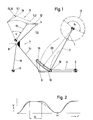
- Fig. 1 das erfindungsgemäße Koppelrastgetriebe, wobei der Antrieb über einen Schubkurbeltrieb erfolgt,
- Fig. 2 das Verhältnis der Bewegungsgrößen ϕ,ψ und den Verstellbereich von ϕR (gestrichelte Linie),
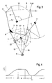
- Fig. 3 eine weitere Antriebsalternative mittels Antriebskurbel und Kulissenführung, geeignet für einen stark ungleichförmigen Betrieb im Vor- und Rücklauf der Antriebsschwinge,
- Fig. 4 die Beziehung zwischen Abtriebsschwingwinkel ψ und Kurbelwinkel ϕ gemäß Ausführung nach Fig. 3,
- Fig. 5 ein Kombinationskoppelrastgetriebe für beispielsweise zwei gleichgroße Rastwinkel mit einer Verstellmöglichkeit derselben als weiterführende Variante des rasterzeugenden Grundgetriebes,
- Fig. 6 die für die Ausführung gemäß Fig. 5 geltende Beziehung zwischen den Rastwinkeln ϕRI, ϕRI und Abtriebsschwingwinkel ψ,
- Fig. 7 das Grundgetriebe nach Fig. 1 in einem ersten Anwendungsfall als Antriebs- und Steuermechanismus eines Prägetiegels in Tiegeldruckmaschinen,
- Fig. 8 das Doppelrastgetriebe nach Fig. 5 als Antrieb für einen Farb- oder Feuchtheber in Offset- oder Hochdruckmaschinen und
- Fig. 9 eine Möglichkeit, die Bewegungsübertragung und Rasterzeugung mit nur einem Abtriebshebel durchzuführen.
- 1 the coupling ratchet mechanism according to the invention, the drive being effected via a push crank drive,
- 2 shows the ratio of the movement quantities ϕ, ψ and the adjustment range of ϕ R (dashed line),
- 3 shows a further drive alternative by means of a drive crank and link guide, suitable for a strongly non-uniform operation in the forward and reverse run of the drive rocker,
- 4 shows the relationship between output oscillation angle ψ and crank angle ϕ according to the embodiment according to FIG. 3,
- 5 shows a combination coupling ratchet mechanism for, for example, two identically sized ratchet angles with an adjustment possibility of the same as a further variant of the raster-generating basic transmission,
- 6 shows the relationship between the detent angles ϕ RI , ϕ RI and output oscillation angle ψ, which applies to the embodiment according to FIG. 5,
- 7 in a first application case as the drive and control mechanism of an embossing crucible in crucible printing machines,
- Fig. 8, the double detent gear according to Fig. 5 as a drive for a paint or dampening in offset or high-pressure machines and
- Fig. 9 one way to carry out the motion transmission and grid generation with only one output lever.
Bei der in Fig. 1 dargestellten Grundausführung des Koppelrastgetriebes erfolgt der Antrieb mittels Schubkurbelgetriebe über eine Antriebskurbel 1 sowie eine daran angelenkte Koppel 2, welche an der am Gestelipunkt 3 gelagerten Antriebsschwinge 4 des die ausgeprägte Koppelkurve 5 erzeugenden Gelenkviereckes angelenkt ist. Besagtes Gelenkviereck setzt sich weiter zusammen aus der bereits erwähnten Antriebsschwinge 4; einer daran am Gelenkpunkt 6 angeschlossenen doppelarmigen Koppel 7 sowie einer, an der Verbindungsstelle 8 ihrer beiden Arme 7.1, 7.2 angelenkten weiteren, im Gestellpunkt 9 gelagerten Schwinge 10. Am Endpunkt 11 des abtriebsseitigen Koppelarmes 7.2 greift eine rasterzeugende Schwinge 12 eines, dem Gelenkviereck 3,6,8,9 nachgeschalteten Abtriebszweischlages 12,13 an. Die daran angeschlossene Abtriebsschwinge 13 bringt die Bewegungsableitung mit der zwischengeschalteten Rast. Die mit dem dargestellten Gelenkviereck 3,6,8,9 erzeugte Koppelkurve 5 läßt sich in einen kurzen, der Rasterzeugung dienenden Kurvenzug 5.1 und einen, unter einem Winkel 14 langgestreckten, die Bewegungsableitung hervorbringenden Kurvenzug 5.2 trennen.In the basic version of the coupling latching mechanism shown in FIG. 1, the drive takes place by means of a sliding crank mechanism via a drive crank 1 and a
Beide Kurvenzüge 5.1, 5.2 sind durch eine Spitze 15, welche die Koppelkurve 5 auf ihrer Bahn durchläuft, scharf voneinander getrennt, wobei die besagte Spitze 15 der Koppelkurve 5 mit einem Momentanpol 16 identisch ist, der somit auch Anfang und Ende der Rast markiert. Von dem Grundgedanken ausgehend, diesen speziellen Kurvenverlauf der Koppelkurve 5 zu verwirklichen, der darüber hinaus durch einen sich deckenden Hin- und Rückgang gekennzeichnet sein soll, sind die Abmessungen und Lagen des Gelenkviereckes 3,6,8,9 mit Hilfe des Polortkurvenverfahrens zu ermitteln. Das Zusammenfügen zu der vorliegenden Getriebeeinheit kann in einer synthetisch empirischen Vorgehensweise gelöst werden, wie es jedem Getriebefachmann geläufig ist.Both curves 5.1, 5.2 are sharply separated from one another by a tip 15, which runs through the
Die mit diesem Getriebe 1,2,4,7,10,12,13 erzeugbare Rast ist als Rastwinkel ϕR auf der Kreisbahn 17 der Antriebskurbel 1 dargestellt.The detent that can be generated with this
Zwecks Verstellung der Rastdauer von einem Größtwert stufenlos bis Null herunter ohne Veränderung des Abtriebsschwingwinkels , erhält die Antriebsschwinge 4 einen Verstellschlitz 18, mit dessen Hilfe der Angriffspunkt 19 der antreibenden Koppel 2 auch während des Betriebes stufenlos einstellbar ist. Der Krümmungsradius 20 der Schlitzmittellinie 21 ist dabei in der äußeren Totlage des Getriebes zu bestimmen. Die Verstelleinrichtungen, sowohl für manuelles als auch für automatisches Verstellen, sind recht vielfältig und bedürfen keiner weiteren Präzisierung.For the purpose of adjusting the rest period from a maximum value down to zero without changing the output oscillation angle, the
Das in Figur 2 dargestellte Weg-Zeitdiagramm veranschaulicht die Beziehung zwischen Kurbelwinkel ϕ und Abtriebsschwingwinkel ψ sowie den Verstellbereich des RastwinkelsTR (gestrichelte Linie).The path-time diagram shown in FIG. 2 illustrates the relationship between crank angle ϕ and output oscillation angle ψ and the adjustment range of the detent angle T R (dashed line).
Fig. 3 zeigt eine weitere Antriebsalternative für das rasterzeugende Grundgetriebe 4,7,10,12,13. Dabei treibt eine Antriebskurbel 1 über eine Kulissenführung 22 die Schwinge 10 des Gelenkviereckes 3,6,8,9 an, die nunmehr als Antriebsschwinge wirkt.Fig. 3 shows a further drive alternative for the raster-generating
Eine Verstellmöglichkeit der Rastdauer ergibt sich dabei dadurch, daß der Lagerpunkt 23 der Antriebskurbel 1 verschiebbar ist und zwar dahingehend verschiebbar, daß er sich auf der Verbindungslinie 24 zum Gestellpunkt 9 der Schwinge 10 mittels nicht näher dargestellter Bewegungsmittel bewegen kann. Dadurch ist der Schwenkwinkel der Schwinge 10 stufenlos verstellbar.An adjustment of the rest period results from the fact that the
Das Verhältnis der Bewegungsgrößen ϕ,ψ bei einem Getriebeaufbau gemäß Figur 3 ist aus der Figur 4 ersichtlich. Es zeigt sich dabei eine starke Ungleichförmigkeit im Vor- und Rücklauf der Abtriebsschwinge, ersichtlich aus dem sehr unsymmetrischen Kurvenverlauf der Kurbelwinkel ϕ1 und ϕ2 in Relation zum Abtriebsschwingwinkel ψ. Diese Ausführungsform eignet sich deshalb für solche Aufgaben, die einen derart ungleichförmigen Betrieb fordern.The ratio of the movement variables ϕ, ψ in a gearbox construction according to FIG. 3 can be seen from FIG. 4. This shows a strong non-uniformity in the forward and return of the output rocker, evident from the very asymmetrical curve of the crank angles ϕ 1 and ϕ 2 in relation to the output swing angle ψ. This embodiment is therefore suitable for tasks that require such non-uniform operation.
Figur 5 zeigt eine erweiterte Anwendung des erfindungsgemäßen Koppelrastgetriebes. Dieses Kombinationskoppelrastgetriebe dient der Erzeugung von zwei Rasten Zu diesem Zweck ist dem eigentlichen Grundgetriebe 4,7,10,12,13 ein weiteres Koppelrastgetriebe herkömmlicher Art vorgeschaltet. Dieses erhält seinen Antrieb von einer zentrischen Koppelkurve 25 eines vorhandenen Schubkurbelgetriebes, bestehend aus der Antriebskurbel 1, der Schubstange 26 mit Kulisse 27 sowie einer, am abtriebsseitigen Koppelpunkt 28 der Schubstange 26 angelenkten und durch den Anlenkpunkt 29 mit der Antriebsschwinge 4 des Grundgetriebes 4,7,10,12,13 verbundenen Verbindungsstange 30. Der Antrieb des Schubkurbelgetriebes könnte dabei auch über die Hubbewegung der Kulisse 27 erfolgen. Es handelt sich letztlich um eine Hintereinanderschaltung zweier Rastgetriebe zur Erzeugung, in diesem Falle, zweier gleichgroßer Rasten. Auch bei diesem Getriebe sind die bereits eingangs erwähnten Verstellmöglichkeiten gegeben.FIG. 5 shows an extended application of the coupling detent gear according to the invention. This combination coupling ratchet mechanism is used to generate two notches. For this purpose, the actual
Die für dieses Kombinationskoppelrastgetriebe geltende Beziehung zwischen Kurbelwinkel ; und dem Abtriebsschwingwinkel" ist in Figur 6 dargestellt. Die Rastwinkel ϕRI und ϕRII sind als waagrechte Linien eingezeichnet, wobei zu bemerken ist, daß die mit dem herkömmlichen Rastgetriebe (Schubkurbelgetriebe) erzielbare Rastgüte der Rast ϕRI aufgrund der nur angenäherten Kreisbogenform des rasterzeugenden Kurvenzuges 25.1 der zentrischen Koppelkurve 25 hinter der Güte der Rast ϕRII zurückbleibt.The relationship between crank angle for this combination coupling ratchet mechanism; and the output oscillating angle "is illustrated in FIG. 6, the locking angle φ RI and φ RII are shown as horizontal lines, it being noted that with the conventional latching mechanism (crank mechanism) φ recoverable latching quality of the detent RI due to the only approximately circular arc shape of the raster-forming Curve 25.1 of the
Einen ersten Anwendungsfall des Grundgetriebes zeigt Figur 7. Dabei ist die Abtriebsschwinge 13 mit dem Schwenkhebel 31 des Tiegels 32 einer Tiegeldruckmaschine 33 gekoppelt. Seine Rastposition entspricht dabei der Anlage des Tiegels 32 an der Gegendruckplatte 34, wobei es insbesondere bei Prägetiegeln darauf ankommt, daß während des Druck-bzw. Prägevorganges die Andrückkraft des Tiegels 32 möglichst konstant bleibt. Der Antrieb des Grundgetriebes 4,7,10,12,13 erfolgt im vorliegenden Anwendungsfall beispielsweise über Antriebskurbel 1 sowie Koppel 2.FIG. 7 shows a first application of the basic transmission. The
Die Gestellpunkte 35,9 von Abtriebsschwinge 13 und zweiter Schwinge 10 des Gelenkviereckes sind der Einfachheit halber zusammengelegt. Ebenfalls ist hier in einem Sonderfall der gestellfeste Gelenkpunkt 3 der Antriebsschwinge 4 mit der Spitze 15 der Koppelkurve 5, die gleichzeitig Momentanpol 16 ist, identisch.The frame points 35.9 of the
Ein Anwendungsbeispiel des Kombinationskoppelrastgetriebes gemäß Figur 5 zeigt letztlich die Figur 8. Die Abtriebsschwinge 13 des rasterzeugenden Zweischlages 12,13 eignet sich dabei in besonders vorteilhafter Weise als Schwenkhebel 36 für Farb- oder Feuchthebel 37 in Offset- oder Hochdruckmaschinen. Es ist dabei ein, bezüglich der Güte zumindest einer Rast, gleichwertiger Ersatz für die bisher für diesen Verwendungszweck gebräuchlichen Kurvengetriebe geschaffen. Dabei kann die Anordnung des Kombinationskoppelrastgetriebes derart erfolgen, daß entsprechend den Erfordernissen die Rast mit der höheren Güte mit der Anlage des Hebers 37 an der Farbkastenwalze 38 oder auch mit der Anlage an der nachfolgenden Farbwerkwalze 29 übereinstimmt.5 finally shows an application example of the combination coupling ratchet mechanism according to FIG. 8. The
Für die genannten sowie weitere Anwendungsfälle besteht letztlich, wie in Figur 9 dargestellt, gegebenenfalls die Möglichkeit, die rasterzeugende Schwinge 12 sowie die Abtriebsschwinge 13 zu einem Bauteil zusammenzufassen. Der hierfür vorgesehene Abtriebshebel 40 ist zu diesem Zweck mit einem, dem rasterzeugenden kurzen Kurvenzug 5.1 entsprechenden Führungsschlitz 41 versehen, in welchem der als Gleitstein 42 ausgeführte Endpunkt 11 des abtriebsseitigen Koppelarmes 7.2 des schwingenden Gelenkviereckes sich bewegt. Gestaltet man das besagte Gelenkviereck zugleich als Bohr- bzw. Fräsvorrichtung, so läßt sich der genaue Führungsschlitz 41 im Abtriebshebel 40 herstellen. Die absolute Rastgenauigkeit ist damit gewährleistet.For the above-mentioned and other applications, there is ultimately the possibility, as shown in FIG. 9, of combining the grid-generating
Die Erfindung ist natürlich keinesfalls auf die dargestellten Ausführungsformen und Verwendungszwecke beschränkt. Das der Erzeugung der Koppelkurve dienende universelle Grundgetriebe erlaubt nämlich mit einem vorgeschalteten mehrgliedrigen Gelenkgetriebe unterschiedlichste Getriebekombinationen, so daß von einem Punkt' einer Koppel-, Schub- oder Kreisbewegung aus die Antriebsherleitung für das Grundgetriebe erfolgen kann. Insbesondere bei der Ausführung nach Figur 5 kann die Bewegungsherleitung (Antrieb) von jedem beliebigen Punkt einer Schubebene erfolgen. Weiterhin bestehen in Abänderung der jeweiligen Getriebegeometrie mannigfaltige Möglichkeiten der Zusammenlegung verschiedener Gestellpunkte. Weiterhin ist es mit diesem Getriebe auf einfache Art und Weise möglich, die aus einer Schwenkbewegung der Abtriebsschwinge sich ergebende Rast als Stillstand einer Hubbewegung eines in Längsrichtung geführten Stößels umzuwandeln.The invention is of course in no way limited to the illustrated embodiments and uses. The serving the generation of the coupler curve universal basic transmission allows namely an upstream multi-membered linkage diverse gear combinations, so that can be done from the Antriebsherleitung for the basic transmission from a point 'a coupling, thrust or circular motion. In the embodiment according to FIG. 5 in particular, the derivation of motion (drive) can take place from any point on a thrust plane. Furthermore, there are various possibilities of merging different frame points by changing the respective gear geometry. Furthermore, with this gear it is possible in a simple manner to convert the detent resulting from a pivoting movement of the output rocker as the standstill of a lifting movement of a ram guided in the longitudinal direction.
- 1 Antriebskurbel1 drive crank
- 2 Koppel2 paddocks
- 3 Verstellpunkt3 adjustment point
- 4 Antriebsschwinge4 drive arm
- 5 Koppelkurve5 coupling curve
- 5.1 Kurzer Kurvenzug5.1 Short curve
- 5.2 Langgestreckter Kurvenzug5.2 Elongated curve
- 6 Gelenkpunkt6 pivot point
- 7 Doppelarmige Koppel7 double-armed belt
- 7.1 Koppelarm7.1 Coupling arm
- 7.2 Abtriebseitiger Koppelarm7.2 Coupling arm on the output side
- 8 Verbindungsstelle8 connection point
- 9 Gestellpunkt9 rack point
- 10 Schwinge10 swingarm
- 11 Endpunkt (Gelenk)11 end point (joint)
- 12 Rasterzeugende Schwinge (Lenker)12 grid-producing swing arm (handlebar)
- 13 Abtriebsschwinge13 output rocker
- 14 Winkel14 angles
- 15 Spitze15 tip
- 16 Momentanpol16 instantaneous pole
- ϕR RastwinkelRast R detent angle
- 17 Kreisbahn17 circular path
- 18 Verstellschlitz18 adjustment slot
- 19 Angriffspunkt19 point of attack
- 20 Krümmungsradius20 radius of curvature
- 21 Schlitzmittellinie21 slot center line
- ϕ Kurbelwinkelϕ crank angle
- ψ Abtriebsschwingwinkelψ output oscillation angle
- 22 Kulissenführung22 guided tour
- 23 Lagerpunkt23 bearing point
- 24 Verbindungslinie24 connecting line
- 25 Zentrische Koppelkurve25 centric coupling curve
- 26 Schubstange26 push rod
- 27 Kulisse27 backdrop
- 28 Koppelpunkt28 crosspoint
- 29 Anlenkpunkt29 pivot point
- 30 Verbindungsstange30 connecting rod
- 31 Schwenkhebel31 swivel lever
- 32 Tiegel (Prägetiegel)32 crucibles
- 33 Tiegeldruckmaschine33 crucible printing machine
- 34 Gegendruckplatte34 counter pressure plate
- 35 Gestellpunkt35 rack point
- 36 Schwenkhebel36 swivel levers
- 37 Farbheber, Feuchtheber37 color lifter, damp lifter
- 3 8 Farbkastenwalze3 8 ink fountain roller
- 39 Farbwerkwalze39 inking roller
- 40 Abtriebshebel40 output lever
- 41 Führungsschlitz41 guide slot
- 42 Gleitstein42 sliding block
Claims (11)
dadurch gekennzeichnet,
daß die Koppelkurve (5) auf ihrer Bahn eine Spitze (15) aufweist, welche sie in zwei Kurvenzüge (5.1,5.2) teilt, wobei ein kurzer Kurvenzug (5.1) der Rasterzeugung dient, während ein unter einem Winkel (14) langgestreckter Kurvenzug (5.2) die Bewegungsableitung hervorbringt und die Spitze (15) der Koppelkurve (5) mit einem Momentanpol (16) identisch ist, der Anfang und Ende der Rast markiert.1. Gear (4,7,10,12,13) for executing movements with downtimes switched on, consisting of an oscillatable quadrangular joint (3,6,8,9) with the associated joint members (4,7,10), the Coupling curve (5) is only partially traversed and is congruent in the outward and return runs, as well as a grid-generating output two-stroke (12, 13),
characterized,
that the coupling curve (5) has a tip (15) on its path, which divides it into two curves (5.1,5.2), a short curve (5.1) serving to generate the grid, while a curve (elongated at an angle (14) 5.2) produces the movement derivative and the tip (15) of the coupling curve (5) is identical to a momentary pole (16) which marks the beginning and end of the rest.
dadurch gekennzeichnet,
daß am Gelenkpunkt (6) der Antriebsschwinge (4) des Gelenkviereckes (3,6,8,9) eine doppelarmige Koppel (7) angreift, wobei an der Verbindungsstelle (8) ihrer beiden Arme die zweite Schwinge (10) des Gelenkviereckes (3,6,8,9) schwenkbar gelagert ist, daß weiterhin am abtriebsseitigen Koppelarm (7.2) besagter Koppel (7) eine rasterzeugende Schwinge (12) angreift, an deren anderen Ende die Abtriebsschwinge (13) angelenkt ist.2. Transmission according to claim 1,
characterized,
that a double-armed coupling (7) engages at the articulation point (6) of the drive rocker (4) of the articulated quadrilateral (3, 6, 8, 9), the second rocker (10) of the articulated quadrilateral (3 , 6, 8, 9) is pivotably mounted so that a coupling-generating rocker (12), on the output-side coupling arm (7.2) of said coupling (7), acts on the other end of which the output rocker (13) is articulated.
dadurch gekennzeichnet,
daß an der Antriebsschwinge (4) des Gelenkviereckes (3,6,8,9) die Koppel (2) eines Schubkurbelgetriebes (1,2) angreift.3. Transmission according to claim 1 and 2,
characterized,
that the coupling (2) of a sliding crank mechanism (1, 2) engages on the drive rocker (4) of the four-bar linkage (3, 6, 8, 9).
gekennzeichnet durch
einen kreisbogenförmigen Verstellschlitz (18), der auf der Ahtriebsschwinge (4) des Gelenkviereckes (3,6,8,9) angeordnet ist, um über eine Verschiebung des Angriffspunktes (19) der antreibenden Koppel (2) eine Verstellung der Rastdauer ,von einem Maximum ausgehend bis Null, zu erreichen, ohne Veränderung des Abtriebsschwingwinkels ψ.4. Transmission according to claim 3,
marked by
an arcuate adjustment slot (18) which is arranged on the drive rocker (4) of the four-bar linkage (3, 6, 8, 9) in order to adjust the detent duration by moving the engagement point (19) of the driving coupling (2) Maximum starting to reach zero without changing the output oscillation angle ψ.
dadurch gekennzeichnet,
daß die Verstellung der Rastdauer auch während des Betriebes erfolgen kann.5. Transmission according to claim 4,
characterized,
that the rest period can also be adjusted during operation.
dadurch gekennzeichnet,
daß die zweite Schwinge (10) des Gelenkviereckes (3,6,8,9) mit einer antreibenden Kurbel (1) über eine Kulissenführung (22) direkt verbunden ist.6. Transmission according to claim 1 and 2,
characterized,
that the second rocker (10) of the four-bar linkage (3, 6, 8, 9) is connected directly to a driving crank (1) via a link guide (22).
dadurch gekennzeichnet,
daß zur Erzeugung von zwei Rastwinkeln (ϕRI, ϕRII) und eines gemeinsamen Abtriebsschwingwinkels (ψ) dem rasterzeugenden Grundgetriebe (4,7,10,12,13) im Koppelpunkt (28) über eine Verbindungsstange (30) ein weiteres Rastgetriebe vorgeschaltet ist, welches seinen Antrieb von einer zentrischen Koppelkurve (25) eines vorhandenen Schubkurbelgetriebes (1,26,27) ableitet.7. Transmission according to claim 1,
characterized,
that for generating two detent angles (ϕ RI , ϕ RII ) and a common output oscillation angle (ψ) the detent-generating basic gear (4,7,10,12,13) in the coupling point (28) upstream of a connecting rod (30) a further detent gear , which derives its drive from a central coupling curve (25) of an existing thrust crank mechanism (1, 26, 27).
dadurch gekennzeichnet,
daß die Antriebsherleitung von einer geradlinigen Schubkurbelbewegung von jeder beliebigen Stelle der Schubebene aus abnehmbar ist.8. Transmission according to claim 7,
characterized,
that the drive derivation from a straight-line thrust movement can be removed from any point on the thrust plane.
dadurch gekennzeichnet,
daß die Abtriebsschwinge (13) des Grundgetriebes (4,7,10,12,13) als Antriebsgelenk für einen Prägetiegel (32) einer Tiegeldruckmaschine (33) verwendet wird, wobei die Rast der Abtriebsschwinge (13) während des Prägevorgangs erfolgt.9. Transmission according to claim 1,
characterized,
that the output rocker (13) of the basic gear (4,7,10,12,13) is used as a drive joint for an embossing crucible (32) of a crucible printing machine (33), the output rocker (13) being locked during the embossing process.
dadurch gekennzeichnet,
daß die, eine Doppelrast erzeugende Abtriebsschwinge (13) des Doppelrastgetriebes (4,7,10,12,13; 1,26,27,30) als Schwenkhebel (36) eines Hebers (37) in Farb- oder Feuchtwerken von Druckmaschinen verwendet wird, wobei die Endstellungen des Hebers (37) mit den Raststellungen identisch sind.10. Transmission according to claim 7,
characterized,
that the output rocker (13) of the double detent gear (4,7,10,12,13; 1,26,27,30) producing a double detent is used as a pivoting lever (36) of a lifter (37) in inking or dampening units of printing machines , the end positions of the lifter (37) being identical to the locking positions.
dadurch gekennzeichnet,
daß die Bewegungsübertragung und Rasterzeugung über einen Abtriebshebel (40) erfolgt, der mit einem, dem rasterzeugenden kurzen Kurvenzug (5.1) entsprechenden Führungsschlitz (41) versehen ist, in welchem der als Gleitstein (42) ausgeführte Endpunkt (11) des abtriebsseitigen Koppelarmes (7.2) des schwingenden Gelenkviereckes sich bewegt.11. Transmission according to claim 1,
characterized,
that the motion transmission and grid generation takes place via an output lever (40) which is provided with a guide slot (41) corresponding to the short curve (5.1) generating the grid, in which the end point (11) of the coupling arm (7.2.) designed as a sliding block (42) ) of the swinging quadrangle moves.
Applications Claiming Priority (2)
| Application Number | Priority Date | Filing Date | Title |
|---|---|---|---|
| DE3116172A DE3116172C2 (en) | 1981-04-23 | 1981-04-23 | "Gearbox for executing movements with switched-on downtimes" |
| DE3116172 | 1981-04-23 |
Publications (3)
| Publication Number | Publication Date |
|---|---|
| EP0063717A2 true EP0063717A2 (en) | 1982-11-03 |
| EP0063717A3 EP0063717A3 (en) | 1983-11-16 |
| EP0063717B1 EP0063717B1 (en) | 1986-05-28 |
Family
ID=6130687
Family Applications (1)
| Application Number | Title | Priority Date | Filing Date |
|---|---|---|---|
| EP82102866A Expired EP0063717B1 (en) | 1981-04-23 | 1982-04-03 | Transmission for performing movements with intercalated periods of standstill |
Country Status (4)
| Country | Link |
|---|---|
| US (1) | US4416198A (en) |
| EP (1) | EP0063717B1 (en) |
| JP (3) | JPS57184746A (en) |
| DE (2) | DE3116172C2 (en) |
Families Citing this family (8)
| Publication number | Priority date | Publication date | Assignee | Title |
|---|---|---|---|---|
| EP0557393A4 (en) * | 1990-11-09 | 1995-05-10 | Greencare Pty Ltd | Drive linkage for agricultural device |
| US5320208A (en) * | 1992-07-02 | 1994-06-14 | Utica Enterprises, Inc. | Reciprocating lift mechanism |
| DE19835005B4 (en) * | 1997-12-20 | 2016-08-11 | Heidelberger Druckmaschinen Ag | Cam-controlled power balancing gear for a bow acceleration system |
| US6935228B2 (en) * | 2000-05-17 | 2005-08-30 | Brandtjen & Kluge, Inc. | Platen press |
| WO2002059468A1 (en) * | 2001-01-26 | 2002-08-01 | Helmut Obieglo | Internal combustion engine with articulated connecting rod and prolonged upper dead center time |
| US9782817B2 (en) | 2014-06-10 | 2017-10-10 | Getter Dunn Technologies, Llc | System and method of varying dwell time in a honeycomb plate press |
| US10421207B2 (en) * | 2014-10-09 | 2019-09-24 | Phoenix Partners, Llc | Adjustable clamshell press |
| US10915672B2 (en) * | 2017-08-31 | 2021-02-09 | Autodesk, Inc. | Computer-implemented synthesis of a four-bar linkage |
Citations (3)
| Publication number | Priority date | Publication date | Assignee | Title |
|---|---|---|---|---|
| DE566021C (en) * | 1929-09-18 | 1932-12-08 | Hermann Alt Dr | Gearbox for executing movements with switched-on downtimes |
| DE670678C (en) * | 1939-01-23 | Leo Hagedorn | Linkage | |
| DE719040C (en) * | 1936-09-04 | 1943-01-12 | Wuerker Fa | Gear for control movements, especially for the generation of standstills |
Family Cites Families (12)
| Publication number | Priority date | Publication date | Assignee | Title |
|---|---|---|---|---|
| US346635A (en) * | 1886-08-03 | Dewend | ||
| DE428026C (en) * | 1926-04-23 | George Constantinesco | Procedures and facilities for the transfer of services | |
| US667772A (en) * | 1900-08-15 | 1901-02-12 | Barnhart Brothers & Spindler | Throw-off attachment for printing-presses. |
| US1095675A (en) * | 1911-06-01 | 1914-05-05 | Giacomo Rietti | Combustion-engine. |
| US1121705A (en) * | 1912-10-22 | 1914-12-22 | Harris Automatic Press Co | Actuating means for fountain-rolls for printing-presses. |
| US1656601A (en) * | 1922-06-14 | 1928-01-17 | Smithe Machine Co Inc F L | Plunger mechanism |
| US2574137A (en) * | 1946-03-22 | 1951-11-06 | Teletype Corp | Stop for reciprocating members |
| US2523430A (en) * | 1948-08-23 | 1950-09-26 | Henry T Hearn | Reciprocating die actuating means |
| US2503037A (en) * | 1948-08-23 | 1950-04-04 | Danly Mach Specialties Inc | Multiple action power press |
| FR59274E (en) * | 1949-05-09 | 1954-05-24 | Lever transmission between piston and crankshaft for engines and other machines | |
| DE1217539B (en) * | 1957-10-29 | 1966-05-26 | Liebrandt Karl | Warp knitting machine |
| CH422013A (en) * | 1964-02-19 | 1966-10-15 | Roland Offsetmaschf | Inking unit |
-
1981
- 1981-04-23 DE DE3116172A patent/DE3116172C2/en not_active Expired
-
1982
- 1982-04-03 DE DE8282102866T patent/DE3271329D1/en not_active Expired
- 1982-04-03 EP EP82102866A patent/EP0063717B1/en not_active Expired
- 1982-04-22 US US06/370,622 patent/US4416198A/en not_active Expired - Fee Related
- 1982-04-23 JP JP57067517A patent/JPS57184746A/en active Pending
- 1982-04-23 JP JP1982058582U patent/JPS57205438U/ja active Pending
-
1988
- 1988-11-17 JP JP1988149106U patent/JPH01139162U/ja active Pending
Patent Citations (3)
| Publication number | Priority date | Publication date | Assignee | Title |
|---|---|---|---|---|
| DE670678C (en) * | 1939-01-23 | Leo Hagedorn | Linkage | |
| DE566021C (en) * | 1929-09-18 | 1932-12-08 | Hermann Alt Dr | Gearbox for executing movements with switched-on downtimes |
| DE719040C (en) * | 1936-09-04 | 1943-01-12 | Wuerker Fa | Gear for control movements, especially for the generation of standstills |
Non-Patent Citations (2)
| Title |
|---|
| FEINWERKTECHNIK, Band 54, Nr. 1, 1950 K. HAIN "Zur Weiterentwicklung der Koppelrastgetriebe", Seiten 9-15 * |
| Getriebetechnik, Volmer, Berlin 1979, S. 132, 133 * |
Also Published As
| Publication number | Publication date |
|---|---|
| EP0063717B1 (en) | 1986-05-28 |
| DE3271329D1 (en) | 1986-07-03 |
| EP0063717A3 (en) | 1983-11-16 |
| DE3116172C2 (en) | 1983-03-03 |
| DE3116172A1 (en) | 1982-11-11 |
| JPS57205438U (en) | 1982-12-27 |
| JPH01139162U (en) | 1989-09-22 |
| US4416198A (en) | 1983-11-22 |
| JPS57184746A (en) | 1982-11-13 |
Similar Documents
| Publication | Publication Date | Title |
|---|---|---|
| DE2755361C2 (en) | Folding jaw cylinder for rotary folder | |
| EP0242661A2 (en) | Positioning device for a five-cylinder printing unit of a rotary offset printing machine | |
| EP0392205B1 (en) | Rotary printing machine for sheets with several units for printing recto and recto-verso | |
| EP0063717B1 (en) | Transmission for performing movements with intercalated periods of standstill | |
| DE3623647A1 (en) | DEVICE FOR THE STEP-BY-STEP PROCESSING OF TAPE MATERIAL WITH TWO COUNTER-DRIVING DRIVE ROLLERS | |
| WO2001051234A1 (en) | Device mounted onto a slider crank for generating a displacement of a part mounted onto the slide in relation to the latter | |
| EP1336440A1 (en) | Driver device for workpieces with transfer bars | |
| DE2340263A1 (en) | DRIVE FOR MULTI-COLOR SHEET ROTATION MACHINES IN A ROW ARRANGEMENT WITH AT LEAST TWO PRINTING UNITS | |
| DE4442302B4 (en) | Device for the axial reciprocation of friction rollers in the inking unit of printing presses | |
| EP0041690B1 (en) | Multistage metal-forming machine | |
| DE2402836C2 (en) | Screen printing device with at least two printing stations | |
| DE3001630C2 (en) | Drive device | |
| DE102007009884C5 (en) | printing press | |
| EP0480879A1 (en) | Device for infinitely varying the axial stroke of vibrating inking rollers | |
| DE10143042A1 (en) | Print copies folding device in web-fed rotary printing machine, has pair of toggle levers operated through double crank, to reciprocate folding knife in single plane | |
| DE3222128A1 (en) | Intermittently working feed attachment, in particular gripper feed attachment for eccentric presses | |
| DE2148801A1 (en) | ROLL SHAPING MACHINE FOR THE PRODUCTION OF GEARS OR THE LIKE | |
| DD278538A5 (en) | DEVICE FOR CONTROLLING THE TOOL POSITION AS A RESULT FROM THE LIFTING POSITION | |
| DE2911576A1 (en) | FAST-RUNNING MACHINE FOR COLD FORGING SCREWS, RIVETS, ETC. HARDWARE | |
| EP1825989A1 (en) | Apparatus for forming, punching and stacking thermoformed plastic parts | |
| EP0515882B1 (en) | Device for changing the lever-ratio of a two-armed oscillating lever | |
| DE2126697A1 (en) | Device with spindle drive for lifting paper rolls and similar heavy cylindrical objects | |
| DE1140207B (en) | Switching drive for the ink fountain roller of a printing machine | |
| DE1552092A1 (en) | Drive for a transport device | |
| DE4303017A1 (en) | Toggle lever press with ram coupled to press plate |
Legal Events
| Date | Code | Title | Description |
|---|---|---|---|
| PUAI | Public reference made under article 153(3) epc to a published international application that has entered the european phase |
Free format text: ORIGINAL CODE: 0009012 |
|
| AK | Designated contracting states |
Designated state(s): CH DE FR GB IT |
|
| PUAL | Search report despatched |
Free format text: ORIGINAL CODE: 0009013 |
|
| AK | Designated contracting states |
Designated state(s): CH DE FR GB IT LI |
|
| 17P | Request for examination filed |
Effective date: 19831209 |
|
| GRAA | (expected) grant |
Free format text: ORIGINAL CODE: 0009210 |
|
| AK | Designated contracting states |
Kind code of ref document: B1 Designated state(s): CH DE FR GB IT LI |
|
| REF | Corresponds to: |
Ref document number: 3271329 Country of ref document: DE Date of ref document: 19860703 |
|
| ITF | It: translation for a ep patent filed |
Owner name: STUDIO JAUMANN |
|
| ET | Fr: translation filed | ||
| PLBE | No opposition filed within time limit |
Free format text: ORIGINAL CODE: 0009261 |
|
| STAA | Information on the status of an ep patent application or granted ep patent |
Free format text: STATUS: NO OPPOSITION FILED WITHIN TIME LIMIT |
|
| 26N | No opposition filed | ||
| PG25 | Lapsed in a contracting state [announced via postgrant information from national office to epo] |
Ref country code: GB Effective date: 19890403 |
|
| PG25 | Lapsed in a contracting state [announced via postgrant information from national office to epo] |
Ref country code: LI Effective date: 19890430 Ref country code: CH Effective date: 19890430 |
|
| GBPC | Gb: european patent ceased through non-payment of renewal fee | ||
| PG25 | Lapsed in a contracting state [announced via postgrant information from national office to epo] |
Ref country code: FR Free format text: LAPSE BECAUSE OF NON-PAYMENT OF DUE FEES Effective date: 19891228 |
|
| REG | Reference to a national code |
Ref country code: CH Ref legal event code: PL |
|
| REG | Reference to a national code |
Ref country code: FR Ref legal event code: ST |
|
| PGFP | Annual fee paid to national office [announced via postgrant information from national office to epo] |
Ref country code: DE Payment date: 19940505 Year of fee payment: 13 |
|
| EUG | Se: european patent has lapsed |
Ref document number: 82102866.9 Effective date: 19821216 |
|
| PG25 | Lapsed in a contracting state [announced via postgrant information from national office to epo] |
Ref country code: DE Effective date: 19960103 |