EP0063501A1 - Vibration transmission member and working machine provided with such a member - Google Patents
Vibration transmission member and working machine provided with such a member Download PDFInfo
- Publication number
- EP0063501A1 EP0063501A1 EP82400260A EP82400260A EP0063501A1 EP 0063501 A1 EP0063501 A1 EP 0063501A1 EP 82400260 A EP82400260 A EP 82400260A EP 82400260 A EP82400260 A EP 82400260A EP 0063501 A1 EP0063501 A1 EP 0063501A1
- Authority
- EP
- European Patent Office
- Prior art keywords
- housing
- core
- transmission member
- arms
- member according
- Prior art date
- Legal status (The legal status is an assumption and is not a legal conclusion. Google has not performed a legal analysis and makes no representation as to the accuracy of the status listed.)
- Granted
Links
Images

Classifications
-
- B—PERFORMING OPERATIONS; TRANSPORTING
- B06—GENERATING OR TRANSMITTING MECHANICAL VIBRATIONS IN GENERAL
- B06B—METHODS OR APPARATUS FOR GENERATING OR TRANSMITTING MECHANICAL VIBRATIONS OF INFRASONIC, SONIC, OR ULTRASONIC FREQUENCY, e.g. FOR PERFORMING MECHANICAL WORK IN GENERAL
- B06B3/00—Methods or apparatus specially adapted for transmitting mechanical vibrations of infrasonic, sonic, or ultrasonic frequency
-
- G—PHYSICS
- G10—MUSICAL INSTRUMENTS; ACOUSTICS
- G10K—SOUND-PRODUCING DEVICES; METHODS OR DEVICES FOR PROTECTING AGAINST, OR FOR DAMPING, NOISE OR OTHER ACOUSTIC WAVES IN GENERAL; ACOUSTICS NOT OTHERWISE PROVIDED FOR
- G10K3/00—Rattles or like noise-producing devices, e.g. door-knockers
Definitions
- the present invention relates generally to the transmission members, or bearings, intended to be interposed between a first member, said here for convenience driving member, and a second member, said here for convenience driven member, and is for example the case where the driven member constitutes by itself a vibrating machining tool or is associated with such a tool.
- the transmission components proposed to date for this purpose can for example constitute bearings comprising shock absorbers made of elastic material, bearings using elastic diaphragms, or bearings with hydro or aerodynamic suspension.
- At least some of them comprise, on the one hand a hollow housing, for fixing to the frame forming a reference support, and on the other hand, a core mounted floating in all directions in said housing, said core comprising at least two arms. , which both open to the outside of the housing, and to each of which any driving or driven member is liable to be subjected.
- the two arms of the floating core are always in practice arranged in alignment with one another.
- the driving member and the driven member are both inevitably interposed between the head of the machine frame carrying the assembly and the work table of this frame on which the workpiece is placed. to work.
- the driving member and the driven member necessarily have a length at least equal to the half-wavelength of these vibrations, which is generally appreciable.
- the power capable of being brought into play is limited to that of the single driving member capable of being used.
- the positioning provided for the tool forming the driven member lacks precision.
- the subject of the present invention is in particular a transmission member or bearing with suspension by fluid suitable for avoiding these drawbacks and also having other advantages; it also relates to a machining machine using such a transmission member.
- the transmission member according to the invention which, in general, is therefore intended to be interposed between a first member, said here for convenience, driving member, and a second member, said here for convenience, driven member, and which is of the type comprising a hollow housing and a core mounted floating in all directions in said housing, said core itself comprising at least two arms which both open out of the housing, and to each of which a any driving or driven member is liable to be secured, is characterized in that the arms of said core form an angle between them, the housing internally comprises a housing whose configuration is a homothetic replica of that of the core, a clearance being provided in any direction between said core and said housing, and at least part of each of the walls of said housing which are opposite the arms of the core comprises at least one recess, which, by a network of pipes internal to the housing, is susceptible ble to be put in communication with a source of pressurized lifting fluid.
- the angle between the arms of the core is 90 °.
- the arrangement according to the invention which is therefore characterized, according to this aspect, by the fact that the arm to which the driving member is coupled and that to which the driven member is subjected are not necessarily in alignment of each other, and which takes advantage of the experimental fact that a piece of which one arm is subjected to vibrations similarly pass on these vibrations to the other arms that it may comprise, whatever the orientation of the latter relative to the arm subjected to said vibrations, advantageously allows a significant reduction in the size of the assembly.
- the vibration generator forming the driving member is not necessarily interposed axially between the frame head to be fitted and the corresponding work table.
- the core comprises four arms, in practice arranged in a cross.
- the lifting fluid used is preferably elastically compressible, so as not to transmit vibrations between the core and the housing.
- a transmission member in a machining machine implementing a transmission member according to the invention, interposed between a frame head of this machine and a driven member, which can be a tool or machining member, the member or workpiece then being suitably secured to any support, a work table for example, facing the frame head, or which, in reverse arrangement, may be the member or workpiece, the tool or member machining then being subject to said support, said transmission member advantageously allows a reduction in the space between the frame head and support, since the vibration generator can then extend laterally, which facilitates the implementation of a such a vibration generator.
- the shock wave following such a mechanical incident does not propagate laterally, and therefore does not reach the vibration generator (s) used, while the useful vibrations propagate on the contrary in all directions.
- the machining machine concerned can be a simple ultrasonic machining machine.
- this lifting fluid advantageously ensures not only mechanical isolation of the core from the housing, by bathing this core over its entire surface, but also electrical insulation of said core from said housing.
- such a core can be in connection with any member driven under voltage, an electrode of a machine for machining by electro-erosion or electro-chemistry for example.
- the transmission member according to the invention advantageously allows the continuous application of vibrations to such a driven member, even when it is in the course of work, and therefore under load .
- the driven member, machining tool or workpiece being on the one hand subjected to the generator of vibrations and on the other hand connected to an electric generator, there is the simultaneous application, to this driven organ, of mechanical vibrations and of an electric voltage, pulsed or not.
- the transmission member according to the invention advantageously allows real ultrasonic assistance for machining by electro-erosion or electro-chemistry.
- This ultrasonic assistance advantageously leads, in such a case, to machining stability and to a reduction in the formation of arcs between tool and workpiece, the elements dissociated from the mass being mechanically prevented from depositing on that at less of these parts which form the driven member, as well as an increase in the flow rate and a reduction in the deformations of electrodes usually observed.
- the transmission member housing comprising, on either side of the core, in the central zone of the housing thereof, at least one discharge passage suitable for placing this housing in communication with a discharge, for example the atmosphere, for local escape of the lifting fluid injected under pressure in the interval between core and shell, there is provided, according to the invention, on at least one of said evacuation passages, a pressure detector to which the leading organ.
- This pressure detector intervenes as soon as the pressure of the lifting fluid drops below a determined threshold, which, by stopping the vibration generator (s) forming the driving member, advantageously makes it possible to prevent the core from button in charge of the box.
- this security can also intervene on the possible electrical supply of the driven member, to cut this supply.
- the boot of the transmission member according to the invention is externally in the form of a generally parallelepipedal block.
- this configuration advantageously facilitates the fixing of this boot by any of its faces on the frame head of a machine
- this fixing can for example be done, as mentioned above, using an adapter or usual coupling device which, suitably attached to such a case, on one of the faces thereof, is able to cooperate with the fixing device usually provided on such a frame head for mounting a tool.
- the transmission member according to the invention advantageously lends itself, by stacking, to setting up a battery with several similar transmission members, for simultaneous work, in parallel, of a plurality of separate parts on the same machine.
- the transmission member according to the invention is therefore, in summary, advantageously favorable for obtaining good productivity on the machining machines which it equips.
- the transmission member 10 which is intended to be interposed between a first member 11, said here for convenience, driving member, and a second member 12, said here for convenience, driven member , Figure 5, comprises a hollow housing 13, and a core 14 mounted floating in all directions in said housing 13, Figures 1 and 2, said core comprising at least two arms 16, which open one and the other at the outside of the housing 13, and to each of which a driving or driven member is liable to be subjected.
- the arms 16 form an angle between them.
- four arms 16 are provided, which are arranged generally in a cross, and which form two by two between them an angle of 90 °.
- each arm 16 forms for it a straight cross section 18, and this end cross section 18 of each arm 16 is quadrangular.
- This end cross section 18 is for example square.
- the arms 16 of the core 14 are all identical to each other, and, in particular, their end cross sections 18 have the same surface.
- these arms 16 are, at their roots, linked in pairs by cylindrical connecting surfaces 19 with a large radius of curvature.
- the core 14 is generally in the form of a simple solid plate, with parallel faces, from which the arms 16 which it comprises are cut in one piece.
- Such a core 14 can, for example, be made of metal, in particular aluminum, or ceramic.
- the housing 13 is externally in the form of a generally parallelepipedal block.
- a housing 20 Internally, it comprises, for the core 14, a housing 20, the configuration of which is a homothetic replica of that of the core 14, a clearance J being provided in all directions between said core 14 and said housing 20.
- the housing 20 opens on the outside, on four opposite faces two by two of the housing 13, by quadrangular openings 21 homothetic of the end cross sections 18 of the arms 16 of the core 14.
- This clearance J is, for example, less than 0.5 tenths of a mm and preferably less than 2 hundredths of a mm
- such a clearance existing on either side of the core 14, for both directions in any direction it is in total, in any direction, for the two directions combined in such a direction, less than 1 tenth of a mm, and preferably less than 4 hundredths of a mm.
- end cross sections 18 of the arms 16 of the core 14 are flush with the corresponding faces of the housing 13.
- the housing 13 comprises, for defining the housing 20 of the core 14, two flanges 22A, 22B suitably facing one another.
- these flanges 22A, 22B are identical to each other, and, facing one another along a flat median surface 23, they each participate for half, at mid-thickness, in the definition of the housing 20 of the core 14 .
- Each flange 22A, 22B therefore comprises a sole 24 on which protrude, in the corners, four lateral bosses 26.
- the housing 13 further comprises two covers 28A, 28B which are each respectively superposed on the flanges 22A, 22B.
- the flanges 22A, 22B and the covers 28A, 28B which all have the same quadrangular contour, are joined together by threaded tie rods 29, arranged in their angles, parallel to the corresponding edges of the block which they form.
- each of the walls of the housing 20 which are opposite the arms 16 of the core 14 comprises at least one recess, which, by a network of pipes internal to the housing 13, detailed below, is likely to be placed in communication with a source of pressurized lifting fluid.
- said part of the walls of the housing 20 thus comprising nozzles 37 extends from the outlets outside 21 of this housing 20.
- nozzles 37 affect both the sole 24 of the flanges 22A, 22B and the side blocks 26 thereof.
- they extend in two rows in depth, towards the center of the housing 20, and, for each row, they are established in regular steps.
- the pipes provided in the housing 13 for serving the nozzles 37 affecting the side blocks 26 of the flanges 22A, 22B have holes 39 established parallel to each other in these side blocks 26, perpendicular to the corresponding flange 24, said nozzles 37 emerging directly in said holes 39.
- These pipes further comprise grooves 40, which are formed on the surfaces of the flanges 22A, 22B opposite the housing 20, and into which the preceding holes 39 open on the one hand, and, on the other hand, directly, the nozzles 37 of the sole 24 of these flanges 22A, 22B : in practice, in the embodiment shown, two annular grooves 40 concentric are provided, and these communicate transversely with each other by a passage 38.
- the pipes provided for serving the nozzles 37 finally comprise a bore 41 provided in the cover 28A, in line with one of the grooves 40 in the underlying flange 22A.
- this bore 41 of the cover 28A can be connected to a source of pressurized lifting fluid.
- the housing 13 comprises, in the central zone of the housing 20 provided for this core 14, at least one discharge passage 42 suitable for placing said housing in communication with a discharge, for example the atmosphere.
- a single discharge passage 42 is provided on either side of the core 14, and it successively comprises a bore 43 formed in the center of each flange 22A, 22B and a bore 44 formed, in the alignment of the previous one, in the center of each cover 28A, 28B.
- the housing 13 thus formed can be made of metal, for example aluminum, or of synthetic material; its nozzles 37 may for example be cylindrical and have a diameter of the order of 1 mm, and preferably of the order of 0.8 mm.
- the lifting fluid used is injected in the gap between the core 14 and the housing 20 of the housing 13, by the multiplicity of nozzles 37 provided for this purpose in this housing near the outlets outside that these arms 16 of the core 14, and it escapes therefrom through the exhaust section resulting on the one hand from the clearance J existing around said arms 16, at the outlets 21 outside the housing 20, and on the other part of the evacuation passages 42.
- the injection pressure of the lifting fluid is chosen according to the number and the diameter of the nozzles 37, of the exhaust section offered to said fluid, as described above, of the power to be brought into play between the driving member and the driven member concerned, and the amplitude of the vibrations likely to be applied to the core 14 by this driving member.
- this injection pressure is chosen to be sufficient so that, in any event, the core 14 floats, in service, inside the housing 13, without any contact therewith.
- the core 14 is mechanically and electrically isolated from the housing 13 by the cushion of lifting fluid interposed at all points between it and this housing 13, this lifting fluid having been chosen to be elastically compressible so as not to not transmit vibrations and being by itself electrically insulating.
- the transmission member 10 can, for example, be fixed to the frame head 45 of any machining machine, and in particular of a machine for machining by electro-erosion or electro-chemistry, facing any support, work table 55 for example, suitable for holding, for example, the workpiece 57.
- the transmission member 10 For fixing the transmission member 10 according to the invention to the frame head 45, it is attached, for example by screws 46, on one of the faces of its housing 13 comprising at the outlet 21 of the housing 20, tapped holes 75 being provided for this purpose at the corners of this housing 13, an intermediate plate 49, and, the latter by screws 61 implemented by means of recesses 62 formed for this purpose on its underside in the form of embodiment shown in solid lines in Figure 6, is itself reported on an adapter or coupling device 47 suitable for allow connection to the fixing device 48 usually fitted to such a frame head 48.
- Two screws 61 may suffice.
- two screws 46 also may suffice for fixing the intermediate plate 49 to the housing 13; as shown, recesses 62 'can be provided at the upper part thereof for screws.
- the adapter or coupling device 47 may for example be of the type described in US Patent No. 3,271,848, such as those sold under the trade designation "IMEA t '.
- the electrode 12 to be used On the opposite face of the housing 13, it is then attached, at the end of the arm 16 corresponding to the core 14, on the transverse end surface 18 of such an arm 16, the electrode 12 to be used, which, in is a mixed electrode, only the end 50 of this electrode being made of graphite and constituting a machining tool, and said end 50 of this electrode 12 is, by a wire 51, connected to an electric generator 60 capable to charge her.
- the electrode 12 is attached to the core 14 by a threaded tie rod 65, which passes through the female part 63 of the coupling device 47 and the core 14, by means of a bore 66 thereof, for cooperation with a threaded bore 67 of said electrode 12, and which, by its head 68, bears on the opposite face of said core 14.
- the intermediate plate 49 In its central zone, the intermediate plate 49 has a recess 69, serving as a housing for the head 68 of the threaded tie rod 65, without contact with the latter.
- the intermediate plate 49 therefore makes it possible to prevent the vibrations do not propagate towards the coupling device 47.
- the electrode 12 can, for example, as shown in FIG. 6, project, on either side of its threaded bore 67, two pins 71 suitable for cooperating in engagement with complementary housings provided for this purpose on said core 14 (not visible in the figures).
- the vibration generator 11, or transducer is attached by any suitable means to the corresponding arm 16 of the core 14, on the transverse end surface 18 of this arm 16, and a wiring 53 connects it to a generator. impulses 54 appropriate.
- the vibration generator 11 which may for example be of the type sold by the company BRANSON, is attached to the core 14 by means of a threaded captive stud 72, which, on the one hand, cooperates with a threaded bore 73 of said core 14, and which, on the other hand, cooperates with a threaded bore, not visible in the figures, of said vibration generator 11.
- a second vibration generator 11 can, according to the invention, be attached to the arm 16 opposite the core 14, according to provisions similar to those described above.
- the adapter 47 can have any dimension, this dimension not necessarily having to be given to the half-wavelength of the vibrations used.
- the size of the transmission member 10 according to the invention can advantageously be reduced than if a vibration generator 11 was in line with the electrode 12, which facilitates implantation.
- a pressure detector 56 is preferably connected to one of the discharge passages 42 which the housing 13 includes, and, to this pressure detector 56, is controlled the driving member which constitutes the vibration generator 11, the pressure detector 56 controlling for example a switch 59 interposed on the wiring 53 controlling this vibration generator 11.
- a switch 58 also controlled by the pressure detector 56.
- the supply of the vibration generator 11, and possibly also that of the electrode 12, are systematically interrupted, in order to d 'prevent the core 14' from touching the casing 13.
- the pressure detector thus implemented can for example be a simple vacuum flap.
- the usual arrangements are also made so that the machining tool 50 and the workpiece 57 are immersed in an electrolyte.
- the machining tool 50 is carried by the electrode 12 and thus forms the driven member for the transmission member 10 according to the invention, while the member or part to be machined 57 was fixed on the work table 65 of the machine concerned or any other support integral with the frame thereof.
- machining tool 50 which, as before, can be connected by a wire 51 to the electric generator 60.
- the essential is, in the case of a machine for machining by electro-erosion or electro-chemistry, that the establishment of an electrical voltage between the machining tool 50 and the workpiece is ensured. to be machined 57.
- EDM machine As an EDM machine, it is pulsed; being an electro-chemical machining machine, it is pulsed or continuous.
- FIGS. 8 to 10 which relate in solid lines, by way of example, to the single flange 22B of the housing 13, it being understood that the flange 22A, shown diagrammatically in broken lines in FIG. 9, then jointly has an identical constitution, for each of the walls of the housing 20 provided for the core 14, the recess 77 necessary for blowing a lifting fluid extends over the entire width of such a wall.
- such a recess 77 extends, for each of said walls, from one of the bosses 26 framing the latter to the other, and, each of said bosses being affected by a similar recess 77, it belongs, like those here, an annular recess 78 continuously surrounding the arm 16 corresponding to the core 14, in the vicinity of the end of the latter.
- the pipes provided in the corresponding housing 13 for serving the recesses 78 thus formed in the housing 20 thereof comprise, from one recess 78 to another, at least one groove 80, which is formed on the surface of at least one of the flanges 22A, 22B facing said housing 20, and, in practice on the surface in question of each of these flanges 22A, 22B o
- This groove 80 affects each of the studs 26, extending, for example in a curve, as shown, from a recess 77 corresponding to another.
- the feed hole 41 is made in line with one of the recesses 77, and no cover 28A, 28B is necessary.
- the block forming the transmission member according to the invention advantageously has at least three orthogonal faces two by two capable of facilitating its implementation, namely a fixing face , for its adaptation to a machine frame, a power face, for setting up a driving member, and an outlet face, for setting up a driven member.
- one and / or the other of the covers that its housing optionally includes, or one and / or the other of the flanges thereof in the absence of such covers, may be replaced by an intermediate plate which, by a lateral drilling opening on its edge, allows, said drilling intersecting the transverse drilling normally provided for this purpose, a simultaneous supply of lifting fluid from two adjoining bootmakers.
- the core used comprises four arms.
- it may be greater than four, arms extending transversely on either side of a common sill, parallel to one another.
- this core has four cross arms, it is not necessary that from one branch of such a cross to the other said arms have the same length.
- the arms of the core could for example be tuned to the half-wavelength of the vibrations to be implemented, while, for the other branch of said cross, they could be tuned on a multiple of this half wavelength.
- the field of application of the invention is obviously not limited to that of machines for machining by ultrasound, electro-erosion or electro-chemistry, but extends more generally to that of any organ led to subject to vibrations on the part of a leading organ, or even to other actions on the part of such a leading organ, or to that of any driven member subjected to parasitic vibrations, said vibrations not having to be transmitted to the support frame, for example when the driven member is a tool for machining rotating parts.
Abstract
Il s'agit d'un organe de transmission du genre comportant un boîtier creux (13) et un noyau (14) monté flottant dans celui-ci, ledit noyau (14) comportant au moins deux bras (16) à chacun desquels un quelconque organe menant ou mené est susceptible d'être assujetti. Suivant l'invention, les bras (16) du noyau (14) font un angle entre eux, le boîtier (13) comporte intérieurement un logement (20) dont la configuration est une réplique homothétique de celle du noyau (14), un jeu (J) étant prévu en tout sens entre ledit noyau (14) et ledit logement (20) et une partie au moins de chacune des parois dudit logement (20) qui se trouvent en regard des bras du noyau comporte au moins un évidement (37, 77), qui, par un réseau de canalisations internes au boîtier (13), est susceptible d'être mis en communication avec une source de fluide sustentateur sous pression. Application aux machines d'usinage par ultra-sons, électro-érosion ou électro-chimie.It is a type of transmission member comprising a hollow housing (13) and a core (14) mounted floating therein, said core (14) comprising at least two arms (16), each of which any the leading or led organ is liable to be subjugated. According to the invention, the arms (16) of the core (14) form an angle between them, the housing (13) internally comprises a housing (20) whose configuration is a homothetic replica of that of the core (14), a game (J) being provided in any direction between said core (14) and said housing (20) and at least part of each of the walls of said housing (20) which are opposite the arms of the core comprises at least one recess (37 , 77), which, by a network of pipes internal to the housing (13), is capable of being placed in communication with a source of pressurized lift fluid. Application to machining machines using ultrasound, electro-erosion or electro-chemistry.
Description
La présente invention concerne d'une manière générale les organes de transmission, ou paliers, destinés à être interposés entre un premier organe, dit ici par commodité organe menant, et un deuxième organe, dit ici par commodité organe mené, et vise par exemple le cas où l'organe mené constitue par lui-même un outil d'usinage vibrant ou est associé à un tel outil.The present invention relates generally to the transmission members, or bearings, intended to be interposed between a first member, said here for convenience driving member, and a second member, said here for convenience driven member, and is for example the case where the driven member constitutes by itself a vibrating machining tool or is associated with such a tool.
Ainsi qu'on le sait, il est de pratique courante de soumettre des outils à des vibrations mécaniques subsoniques ou ultrasoniques pour en augmenter la productivité.As is known, it is common practice to subject tools to subsonic or ultrasonic mechanical vibrations to increase productivity.
Pour ,qu'un tel outil, formant organe mené, soit ainsi soumis à des vibrations de la part d'un générateur de vibrations, formant organe menant, en pratique un transducteur lui-même soumis à un générateur d'impulsions, un organe de transmission, ou palier, doit être mis en oeuvre entre l'outil et le bâti de la machine qu'équipe celui-ci, pour, d'une part, assurer la fixation de cet outil et son positionnement correct par rapport audit bâti, qui forme support de référence, et pour, d'autre part, permettre l'assujettissement dudit outil audit générateur de vibrations.So that such a tool, forming a driven member, is thus subjected to vibrations from a vibration generator, forming a driving member, in practice a transducer itself subjected to a pulse generator, a transmission, or bearing, must be implemented between the tool and the frame of the machine which the latter equips, to, on the one hand, ensure the fixing of this tool and its correct positioning with respect to said frame, which form reference support, and for, on the other hand, allow the subjugation of said tool to said vibration generator.
Le problème général à résoudre dans la constitution de tels organes de transmission ou paliers, est qu'ils doivent transmettre sans affaiblissement des vibrations du générateur de vibrations formant organe menant à l'outil formant organe mené, mais, d'une part, qu'ils ne doivent pas transmettre ces vibrations au bâti de machine formant support de référence, pour ménager les autres organes portés par celui-ci, et d'autre part, au moins pour certaines applications, et c'est le cas par exemple pour les machines d'usinage par électro-érosion, qu'ils doivent assurer une isolation électrique convenable entre l'outil mis en oeuvre, en l'espèce une électrode de travail, et ledit bâti.The general problem to be solved in the constitution of such transmission members or bearings, is that they must transmit without weakening the vibrations of the vibration generator forming a member leading to the tool forming the driven member, but, on the one hand, that they must not transmit these vibrations to the machine frame forming a reference support, to spare the other organs carried by it, and on the other hand, at least for certain applications, and this is the case for example for machines machining by EDM, they must provide adequate electrical insulation between the tool used, in this case a working electrode, and said frame.
Les organes de transmission proposés à ce jour dans ce but peuvent par exemple constituer des paliers comportant des amortisseurs en matière élastique, des paliers mettant en oeuvre des diaphragmes élastiques, ou des paliers à suspension hydro ou aérodynamique.The transmission components proposed to date for this purpose can for example constitute bearings comprising shock absorbers made of elastic material, bearings using elastic diaphragms, or bearings with hydro or aerodynamic suspension.
Certains au moins d'entre eux comportent, d'une part un boîtier creux, pour la fixation au bâti formant support de référence, et d'autre part un noyau monté flottant en tous sens dans ledit boîtier, ledit noyau comportant au moins deux bras, qui débouchent l'un et l'autre à l'extérieur du boîtier, et à chacun desquels un quelconque organe menant ou mené est susceptible d'être assujetti.At least some of them comprise, on the one hand a hollow housing, for fixing to the frame forming a reference support, and on the other hand, a core mounted floating in all directions in said housing, said core comprising at least two arms. , which both open to the outside of the housing, and to each of which any driving or driven member is liable to be subjected.
Mais, dans les réalisations de ce type, connues à ce jour, les deux bras du noyau flottant sont toujours en pratique disposés dans l'alignement l'un de l'autre.However, in embodiments of this type, known to date, the two arms of the floating core are always in practice arranged in alignment with one another.
Il en résulte de nombreux inconvénients.This results in many disadvantages.
Tout d'abord, seule une transmission linéaire des vibrations est possible de l'organe menant à l'organe mené, en sorte qu'il en résulte un encombrement relativement important pour l'ensemble.First of all, only a linear transmission of vibrations is possible from the member leading to the driven member, so that this results in a relatively large overall size.
En effet, l'organe menant et l'organe mené se trouvent l'un et l'autre inévitablement interposés entre la tête du bâti de machine portant l'ensemble et la table de travail de ce bâti sur laquelle se trouve disposée la pièce à travailler.Indeed, the driving member and the driven member are both inevitably interposed between the head of the machine frame carrying the assembly and the work table of this frame on which the workpiece is placed. to work.
Or, pour satisfaire à de bonnes conditions de transmission de vibrations, l'organe menant et l'organe mené ont-nécessairement une longueur au moins égale à la demi-longueur d'onde de ces vibrations, qui est en général appréciable.However, to satisfy good conditions for transmitting vibrations, the driving member and the driven member necessarily have a length at least equal to the half-wavelength of these vibrations, which is generally appreciable.
En outre, la puissance susceptible d'être mise en jeu se trouve limitée à celle du seul organe menant susceptible d'être mis en oeuvre.In addition, the power capable of being brought into play is limited to that of the single driving member capable of being used.
De plus, et au moins dans certains cas, le positionnement assuré à l'outil formant l'organe mené manque de précision.In addition, and at least in certain cases, the positioning provided for the tool forming the driven member lacks precision.
Enfin, la fixation de l'ensemble à une tête de bâti de machine se fait difficilement avec les conditions d'isolation requises, en raison notamment de l'interposition, entre le boîtier et cette tête de bâti, du générateur de vibrations formant l'organe menant.Finally, it is difficult to fix the assembly to a machine frame head with the required isolation conditions, in particular because of the interposition, between the housing and this frame head, of the vibration generator forming the leading organ.
C'est la raison, notamment, pour laquelle, dans les machines d'usinage par électro-érosion connues à ce jour mettant en oeuvre un outil vibrant, il est nécessaire, en pratique, de faire alterner la mise sous tension de cet outil et l'application de vibrations à celui-ci, ce qui ne permet pas de tirer tout le parti possible d'une telle application de vibrations à un tel outil.This is the reason, in particular, why, in the EDM machines known to date employing a vibrating tool, it is necessary, in practice, to alternate the energizing of this tool and the application of vibrations to it, which does not not allow you to take full advantage of such an application of vibration to such a tool.
La présente invention a notamment pour objet un organe de transmission ou palier à suspension par fluide propre à éviter ces inconvénients et présentant en outre d'autres avantages ; elle a encore pour objet une machine d'usinage mettant en oeuvre un tel organe de transmission.The subject of the present invention is in particular a transmission member or bearing with suspension by fluid suitable for avoiding these drawbacks and also having other advantages; it also relates to a machining machine using such a transmission member.
L'organe de transmission suivant l'invention, qui, d'une manière générale, est donc destiné à être interposé entre un premier organe, dit ici par commodité organe menant, et un deuxième organe, dit ici par commodité organe mené, et qui est du genre comportant un boîtier creux et un noyau monté flottant en tous sens dans ledit boîtier, ledit noyau comportant lui-même au moins deux bras qui débouchent l'un et l'autre à l'extérieur du boîtier, et à chacun desquels un quelconque organe menant ou mené est susceptible d'être assujetti, est caractérisé en ce que les bras dudit noyau font un angle entre eux, le boîtier comporte intérieurement un logement dont la configuration est une réplique homothétique de celle du noyau, un jeu étant prévu en tout sens entre ledit noyau et ledit logement, et une partie au moins de chacune des parois dudit logement qui se trouvent en regard des bras du noyau comporte au moins un évidement, qui, par un réseau de canalisations internes au boîtier, est susceptible d'être mis en communication avec une source de fluide sustentateur sous pression.The transmission member according to the invention, which, in general, is therefore intended to be interposed between a first member, said here for convenience, driving member, and a second member, said here for convenience, driven member, and which is of the type comprising a hollow housing and a core mounted floating in all directions in said housing, said core itself comprising at least two arms which both open out of the housing, and to each of which a any driving or driven member is liable to be secured, is characterized in that the arms of said core form an angle between them, the housing internally comprises a housing whose configuration is a homothetic replica of that of the core, a clearance being provided in any direction between said core and said housing, and at least part of each of the walls of said housing which are opposite the arms of the core comprises at least one recess, which, by a network of pipes internal to the housing, is susceptible ble to be put in communication with a source of pressurized lifting fluid.
Suivant une forme préférée de réalisation, l'angle que font entre eux les bras du noyau est de 90°.According to a preferred embodiment, the angle between the arms of the core is 90 °.
Quoi qu'il en soit, la disposition suivant l'invention, qui se caractérise donc, selon cet aspect, par le fait que le bras auquel est attelé l'organe menant et celui auquel est soumis l'organe mené ne sont pas nécessairement dans l'alignement l'un de l'autre, et qui tire profit du fait expérimental suivant lequel une pièce dont un bras est soumis à des vibrations répercute de manière semblable ces vibrations sur les autres bras qu'elle peut comporter, quelle que soit l'orientation de ceux-ci par rapport au bras soumis auxdites vibrations, permet avantageusement une réduction notable de l'encombrement de l'ensemble.Be that as it may, the arrangement according to the invention, which is therefore characterized, according to this aspect, by the fact that the arm to which the driving member is coupled and that to which the driven member is subjected are not necessarily in alignment of each other, and which takes advantage of the experimental fact that a piece of which one arm is subjected to vibrations similarly pass on these vibrations to the other arms that it may comprise, whatever the orientation of the latter relative to the arm subjected to said vibrations, advantageously allows a significant reduction in the size of the assembly.
En effet, grâce à cette disposition, le générateur de vibrations formant l'organe menant ne se trouve pas nécessairement interposé axialement entre la tête de bâti à équiper et la table de travail correspondante.Indeed, thanks to this arrangement, the vibration generator forming the driving member is not necessarily interposed axially between the frame head to be fitted and the corresponding work table.
Au contraire, il peut être disposé latéralement, et donc sans incidence sur l'encombrement axial de l'ensemble.On the contrary, it can be arranged laterally, and therefore without affecting the axial size of the assembly.
En outre, suivant un développement de l'invention, et conformément à une forme particulière de réalisation de celle-ci, le noyau comporte quatre bras, en pratique disposés en croix.In addition, according to a development of the invention, and in accordance with a particular embodiment of the latter, the core comprises four arms, in practice arranged in a cross.
Ainsi, il est avantageusement possible, suivant les nécessités, d'associer à un même organe mené, un ou plusieurs organes menants, et, donc, d'ajuster au mieux la puissance globale à mettre en jeu pour cet organe menant.Thus, it is advantageously possible, as required, to associate with the same driven member, one or more driving members, and, therefore, to best adjust the overall power to be brought into play for this driving member.
Certes, dans le brevet français N° 1.599.285, il est proposé la mise en oeuvre d'une unité vibratoire qui, à la manière du noyau de l'organe de transmission suivant l'invention, comporte des bras faisant un angle entre eux.Admittedly, in French patent N ° 1,599,285, it is proposed the implementation of a vibratory unit which, like the core of the transmission member according to the invention, includes arms making an angle between them .
Mais, ce brevet français N° 1.599.285, qui, en réalité, vise à obtenir une concentration, sur ladite unité vibratoire, de la puissance de générateurs de vibrations associés à celle-ci, et dont, semble-et-il, le domaine d'application se limite à celui du traitement d'un quelconque fluide auquel est directement appliquée ladite unité vibratoire, ne décrit pas,ni ne suggère, la mise en oeuvre d'une telle unité vibratoire au sein d'un bottier en l'isolant de celui-ci par un fluide sustentateur.However, this French patent No. 1,599,285, which, in reality, aims to obtain a concentration, on said vibratory unit, of the power of vibration generators associated therewith, and of which, it seems, the field of application is limited to that of the treatment of any fluid to which said vibratory unit is directly applied, does not describe, nor suggest, the implementation of such a vibratory unit within a shoemaker in the insulating it by a lifting fluid.
Or, grâce à une telle isolation, il est possible, suivant l'invention, d'éviter toute transmission de vibrations du noyau au boîtier, tout en laissant une pleine liberté de vibration audit noyau.However, thanks to such insulation, it is possible, according to the invention, to avoid any transmission of vibrations from the core to the housing, while leaving full freedom of vibration to said core.
En effet, le fluide sustentateur mis en oeuvre est de préférence élastiquement comprimable, pour ne pas transmettre de vibrations entre le noyau et le boîtier.Indeed, the lifting fluid used is preferably elastically compressible, so as not to transmit vibrations between the core and the housing.
Il s'agit avantageusement d'air.It is advantageously air.
En pratique, dans une machine d'usinage mettant en oeuvre un organe de transmission suivant l'invention, interposé entre une tête de bâti de cette machine et un organe mené, qui peut être un outil ou organe d'usinage, l'organe ou pièce à usiner étant alors convenablement assujetti à un quelconque support, une table de travail par exemple, en regard de la tête de bâti, ou qui, suivant une disposition inverse, peut être l'organe ou pièce à usiner, l'outil ou organe d'usinage étant alors assujetti audit support, ledit organe de transmission permet avantageusement une réduction de l'encombrement entre tête de bâti et support, puisque le générateur de vibrations peut alors s'étendre latéralement, ce qui facilite la mise en oeuvre d'un tel générateur de vibrations.In practice, in a machining machine implementing a transmission member according to the invention, interposed between a frame head of this machine and a driven member, which can be a tool or machining member, the member or workpiece then being suitably secured to any support, a work table for example, facing the frame head, or which, in reverse arrangement, may be the member or workpiece, the tool or member machining then being subject to said support, said transmission member advantageously allows a reduction in the space between the frame head and support, since the vibration generator can then extend laterally, which facilitates the implementation of a such a vibration generator.
Il permet de plus, si désiré, la mise en oeuvre de plusieurs générateurs de vibrations, pour l'obtention d'une puissance de vibrations supérieure, chacun de ces générateurs de vibrations étant implanté latéralement.It also allows, if desired, the use of several vibration generators, to obtain a higher vibration power, each of these vibration generators being located laterally.
Il permet en outre un meilleur positionnement de l'organe mené, outil d'usinage ou pièce à usiner, ce dernier se faisant par son boîtier, et ce boîtier se prêtant lui-même avantageusement à la mise en oeuvre d'un dispositif d'accouplement usuel pour sa fixation à la tête de bâti, ce qui, corollairement, en facilite le déplacement éventuel, et donc celui de l'organe mené, d'une machine d'usinage à une autre.It also allows better positioning of the driven member, machining tool or workpiece, the latter being done by its housing, and this housing advantageously lending itself to the implementation of a device for usual coupling for its attachment to the frame head, which, as a corollary, facilitates the possible displacement, and therefore that of the driven member, from one machining machine to another.
Du fait de l'implantation latérale du ou des générateurs de vibrations mis en oeuvre, il permet enfin, en cas d'incidents mécaniques, d'épargner ce ou ces générateurs de vibrations.Due to the lateral location of the vibration generator (s) used, it finally allows, in the event of mechanical incidents, to save this or these vibration generators.
En effet, de manière surprenante, mais l'expérience le confirme, l'onde de choc consécutive à un tel incident mécanique ne se propage pas latéralement, et donc n'atteint pas le ou les générateurs de vibrations mis en oeuvre, alors que les vibrations utiles se propagent au contraire dans toutes les directions.Indeed, surprisingly, but experience confirms, the shock wave following such a mechanical incident does not propagate laterally, and therefore does not reach the vibration generator (s) used, while the useful vibrations propagate on the contrary in all directions.
La machine d'usinage concernée peut être une simple machine d'usinage par ultra-sons.The machining machine concerned can be a simple ultrasonic machining machine.
Mais il peut être avantageusement tiré profit du fluide sustentateur mis en oeuvre dans l'organe de transmission suivant l'invention pour étendre le champ d'application de celui-ci aux machines d'usinage par électro-érosion (EDM) ou aux machines d'usinage par électrochimie (ECM).However, advantage can be taken of the lifting fluid used in the transmission member according to the invention to extend the field of application thereof to machines for machining by electro-erosion (EDM) or to machines for machining by electrochemistry (ECM).
En effet, ce fluide sustentateur assure avantageusement, non seulement une isolation mécanique du noyau par rapport au boîtier, en baignant sur toute sa surface ce noyau, mais encore une isolation électrique dudit noyau par rapport audit boîtier.In fact, this lifting fluid advantageously ensures not only mechanical isolation of the core from the housing, by bathing this core over its entire surface, but also electrical insulation of said core from said housing.
C'est donc sans inconvénient qu'un tel noyau peut être en liaison avec un quelconque organe mené sous tension, une électrode de machine d'usinage par électro-érosion ou électro- chimie par exemple.It is therefore without disadvantage that such a core can be in connection with any member driven under voltage, an electrode of a machine for machining by electro-erosion or electro-chemistry for example.
Il en résulte que, dans son application à de telles machines, l'organe de transmission suivant l'invention permet avantageusement l'application continue de vibrations à un tel organe mené, même lorsqu'il est en cours de travail, et donc en charge.It follows that, in its application to such machines, the transmission member according to the invention advantageously allows the continuous application of vibrations to such a driven member, even when it is in the course of work, and therefore under load .
Ainsi, suivant une caractéristique des machines d'usinage par électro-érosion ou électro-chimie suivant l'invention, l'organe mené, outil d'usinage ou pièce à usiner, étant d'une part soumis au générateur de vibrations et d'autre part relié à un générateur électrique, il y a l'application simultanée, à cet organe mené, de vibrations mécaniques et d'une tension électrique, pulsée ou non.Thus, according to a characteristic of machines for machining by electro-erosion or electro-chemistry according to the invention, the driven member, machining tool or workpiece, being on the one hand subjected to the generator of vibrations and on the other hand connected to an electric generator, there is the simultaneous application, to this driven organ, of mechanical vibrations and of an electric voltage, pulsed or not.
Autrement dit, l'organe de transmission suivant l'invention permet avantageusement une réelle assistance ultrasonique d'un usinage par électro-érosion ou électro-chimie.In other words, the transmission member according to the invention advantageously allows real ultrasonic assistance for machining by electro-erosion or electro-chemistry.
Cette assistance ultrasonique conduit avantageusement, dans un tel cas, à une stabilité de l'usinage et à une réduction de la formation d'arcs entre outil et pièce à usiner, les éléments dissociés de la masse étant mécaniquement empêchés de se déposer sur celle au moins de ces pièces qui forme l'organe mené, aussi bien qu'à une augmentation du débit et à une réduction des déformations d'électrodes usuellement observées.This ultrasonic assistance advantageously leads, in such a case, to machining stability and to a reduction in the formation of arcs between tool and workpiece, the elements dissociated from the mass being mechanically prevented from depositing on that at less of these parts which form the driven member, as well as an increase in the flow rate and a reduction in the deformations of electrodes usually observed.
Par sécurité, le boîtier de l'organe de transmission suivant l'invention comportant, de part et d'autre du noyau, dans la zone centrale du logement de celui-ci, au moins un passage d'évacuation propre à la mise en communication de ce logement avec une décharge, par exemple l'atmosphère, pour échappement local du fluide sustentateur injecté sous pression dans l'intervalle entre noyau et bottier, il est prévu, suivant l'invention, sur l'un au moins desdits passages d'évacuation, un détecteur de pression auquel est asservi l'organe menant.For safety, the transmission member housing according to the invention comprising, on either side of the core, in the central zone of the housing thereof, at least one discharge passage suitable for placing this housing in communication with a discharge, for example the atmosphere, for local escape of the lifting fluid injected under pressure in the interval between core and shell, there is provided, according to the invention, on at least one of said evacuation passages, a pressure detector to which the leading organ.
Ce détecteur de pression intervient dès que la pression du fluide sustentateur baisse en dessous d'un seuil déterminé, ce qui, par arrêt du ou des générateur(s) de vibrations formant l'organe menant, permet avantageusement d'éviter que le noyau ne touche en charge le boitier.This pressure detector intervenes as soon as the pressure of the lifting fluid drops below a determined threshold, which, by stopping the vibration generator (s) forming the driving member, advantageously makes it possible to prevent the core from button in charge of the box.
Si désiré, le cas échéant, cette sécurité peut également intervenir sur l'alimentation électrique éventuelle de l'organe mené, pour couper cette alimentation.If desired, if necessary, this security can also intervene on the possible electrical supply of the driven member, to cut this supply.
De préférence, enfin, le bottier de l'organe de transmission suivant l'invention se présente extérieurement sous la forme d'un bloc globalement parallélépipédique.Preferably, finally, the boot of the transmission member according to the invention is externally in the form of a generally parallelepipedal block.
Cette configuration facilite avantageusement la fixation de ce bottier par l'une quelconque de ses faces sur la tête de bâti d'une machine, cette fixation pouvant par exemple se faire, comme mentionné ci-dessus, à l'aide d'un adaptateur ou dispositif d'accouplement usuel qui, convenablement rapporté sur un tel bottier, sur l'une des faces de celui-ci, est apte à coopérer avec le dispositif de fixation usuellement prévu sur une telle tête de bâti pour y monter un outil.This configuration advantageously facilitates the fixing of this boot by any of its faces on the frame head of a machine, this fixing can for example be done, as mentioned above, using an adapter or usual coupling device which, suitably attached to such a case, on one of the faces thereof, is able to cooperate with the fixing device usually provided on such a frame head for mounting a tool.
En outre, si désiré, par cette forme parallélépipédique de son boîtier, l'organe de transmission suivant l'invention se prête avantageusement, par empilage, à une mise en batterie avec plusieurs organes de transmission semblables, pour le travail simultané, en parallèle, d'une pluralité de pièces distinctes sur une même machine.In addition, if desired, by this parallelepipedal shape of its housing, the transmission member according to the invention advantageously lends itself, by stacking, to setting up a battery with several similar transmission members, for simultaneous work, in parallel, of a plurality of separate parts on the same machine.
L'organe de transmission suivant l'invention est donc, en résumé, avantageusement favorable à l'obtention d'une bonne productivité sur les machines d'usinage qu'il équipe.The transmission member according to the invention is therefore, in summary, advantageously favorable for obtaining good productivity on the machining machines which it equips.
Les caractéristiques et avantages de l'invention ressortiront d'ailleurs de la description qui va suivre, à titre d'exemple, en référence aux dessins schématiques annexés sur lesquels :
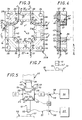
- la figure 1 est une vue en perspective de l'organe de transmission, suivant l'invention, assemblé ;
- la figure 2 en est une vue en perspective éclatée ;
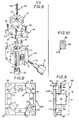
- la figure 3 est, à échelle différente, une vue en plan d'un des flasques constitutifs du boitier que comporte cet organe de transmission, suivant la flèche III de la figure 2 ;
- la figure 4 est, avec un arrachement local, une vue en coupe transversale de ce flasque, suivant la ligne brisée IV-IV de la figure 3 ;
- la figure 5 est une vue en élévation illustrant la mise en oeuvre d'un organe de transmission suivant l'invention dans une machine d'usinage par électro-érosion ;
- la figure 6 est une vue en perspective montrant plus en détail cette mise en oeuvre ;
- la figure 7 reprend pour partie la figure 6, pour une variante de mise en oeuvre ;
- les figures 8 et 9 sont, à échelle différente, des vues respectivement analogues à celles des figures 3, 4, et concernent une variante de réalisation ;
- la figure 10 est une vue transversale en coupe de cette variante, suivant la ligne X-X de la figure 9.
- Figure 1 is a perspective view of the transmission member, according to the invention, assembled;
- Figure 2 is an exploded perspective view;
- Figure 3 is, on a different scale, a plan view of one of the flanges constituting the housing that includes this transmission member, along arrow III of Figure 2;
- Figure 4 is, with a local cutaway, a cross-sectional view of this flange, along the broken line IV-IV of Figure 3;
- Figure 5 is an elevational view illustrating the implementation of a transmission member according to the invention in an electroerosion machining machine;
- Figure 6 is a perspective view showing in more detail this implementation;
- FIG. 7 partly repeats FIG. 6, for an alternative implementation;
- Figures 8 and 9 are, on a different scale, views respectively similar to those of Figures 3, 4, and relate to an alternative embodiment;
- FIG. 10 is a cross-sectional view of this variant, along line XX of FIG. 9.
Tel qu'illustré par ces figures, l'organe de transmission 10 suivant l'invention, qui est destiné à être interposé entre un premier organe 11, dit ici par commodité organe menant, et un deuxième organe 12, dit ici par commodité organe mené, figure 5, comporte un boîtier creux 13, et un noyau 14 monté flottant en tous sens dans ledit boîtier 13,figures 1 et 2, ledit noyau comportant au moins deux bras 16, qui débouchent l'un et l'autre à l'extérieur du boîtier 13, et à chacun desquels un organe menant ou mené est susceptible d'être assujetti.As illustrated by these figures, the
Suivant un aspect de l'invention, les bras 16 font un angle entre eux.According to one aspect of the invention, the
Dans la forme de réalisation représentée, quatre bras 16 sont prévus, qui sont disposés globalement en croix, et qui forment deux à deux entre eux un angle de 90°.In the embodiment shown, four
Dans cette forme de réalisation, l'extrémité de chaque bras 16 forme pour celui-ci une section transversale droite 18, et cette section transversale d'extrémité l8 de chaque bras 16 est quadrangulaire.In this embodiment, the end of each
Cette section transversale d'extrémité 18 est par exemple carrée.This
En pratique, dans la forme de réalisation représentée, les bras 16 du noyau 14 sont tous identiques entre eux, et, notamment, leurs sections transversales d'extrémité 18 ont même surface.In practice, in the embodiment shown, the
Transversalement, ces bras 16 sont, à leur racine, reliés deux à deux par des surfaces cylindriques de raccordement 19 à large rayon de courbure.Transversally, these
En pratique, dans la forme de réalisation représentée, le noyau 14 se présente globalement sous la forme d'une simple plaque massive, à faces parallèles, dans laquelle sont découpés d'un seul tenant les bras l6 qu'il comporte.In practice, in the embodiment shown, the
Un tel noyau 14 peut, par exemple, être réalisé en métal, notamment aluminium, ou en céramique.Such a core 14 can, for example, be made of metal, in particular aluminum, or ceramic.
Lorsqu'il est réalisé en aluminium, il est de préférence anodisé, pour en assurer l'isolation ou contribuer à celle-ci.When it is made of aluminum, it is preferably anodized, to insulate it or contribute to it.
Dans la forme de réalisation représentée, le boîtier 13 se présente extérieurement sous la forme d'un bloc globalement parallélépipédique.In the embodiment shown, the
Intérieurement, il comporte, pour le noyau 14, un logement 20, dont la configuration est une réplique homothétique de celle du noyau 14, un jeu J étant prévu en tous sens entre ledit noyau 14 et ledit logement 20.Internally, it comprises, for the core 14, a
Le logement 20 débouche à l'extérieur, sur quatre faces opposées deux à deux du boîtier 13, par des ouvertures quadrangulaires 21 homothétiques des sections transversales d'extrémité 18 des bras 16 du noyau 14.The
Tel que noté à la figure 1, et tel que schématisé à la figure 3, le jeu J se retrouve donc entre chacun des bords d'une telle section transversale d'extrémité 18 et le bord correspondant de l'ouverture 21 correspondante du boîtier 13.As noted in Figure 1, and as shown schematically in Figure 3, the clearance J is therefore found between each of the edges of such an
Tel que schématisé à la figure 4, il se retrouve également entre les faces principales du noyau 14 et les faces correspondantes du logement 20 du bottier 13.As shown diagrammatically in FIG. 4, it is also found between the main faces of the
Ce jeu J est, par exemple, inférieur à 0,5 dixième de mm et de préférence inférieur à 2 centièmes de mmoThis clearance J is, for example, less than 0.5 tenths of a mm and preferably less than 2 hundredths of a mm
Autrement dit, un tel jeu existant de part et d'autre du noyau 14, pour l'un et l'autre sens de toute direction, il est au total, en toute direction, pour les deux sens confondus d'une telle direction, inférieur à 1 dixième de mm, et de préférence, inférieur à 4 centièmes de mm.In other words, such a clearance existing on either side of the core 14, for both directions in any direction, it is in total, in any direction, for the two directions combined in such a direction, less than 1 tenth of a mm, and preferably less than 4 hundredths of a mm.
Ces valeurs numériques ne sont bien entendu données ici qu'à titre indicatif.These numerical values are of course given here only for information.
Dans la forme de réalisation représentée, les sections transversales d'extrémité 18 des bras 16 du noyau 14 affleurent à niveau avec les faces correspondantes du boîtier 13.In the embodiment shown, the
En outre, dans cette forme de réalisation, le boîtier 13 comporte, pour la définition du logement 20 du noyau 14, deux flasques 22A, 22B convenablement affrontés l'un à l'autre.In addition, in this embodiment, the
En pratique, ces flasques 22A, 22B sont identiques entre eux, et, affrontés l'un à l'autre suivant une surface médiane plane 23, ils participent chacun pour moitié, à mi-épaisseur, à la définition du logement 20 du noyau 14.In practice, these
Chaque flasque 22A, 22B comporte donc une semelle 24 sur laquelle font saillie, dans les angles, quatre bossages latéraux 26.Each
Dans la forme de réalisation représentée sur les figures 1 à 6, le boîtier 13 comporte en outre deux couvercles 28A, 28B qui sont chacun respectivement superposés aux flasques 22A, 22B.In the embodiment shown in Figures 1 to 6, the
Les flasques 22A, 22B et les couvercles 28A, 28B, qui ont tous un même contour quadrangulaire, sont assemblés conjointement par des tirants filetés 29, disposés dans leurs angles, parallèlement aux arêtes correspondantes du bloc qu'ils forment.The
Les têtes 30 de ces tirants filetés 29 prennent appui sur le fond de lamages 31 ménagés à cet effet à la surface du couvercle 28A, et leurs tiges 32 dont seule l'extrémité est visible à la figure 5, traversent successivement, d'abord le couvercle 28A, par des passages 33, puis les flasques 22A, 22B, par des passages 34, avant d'être engagées à vissage dans des passages taraudés 35 du couvercle 28B.The
Intérieurement au boîtier 13, une partie au moins de chacune des parois du logement 20 qui se trouvent en regard des bras 16 du noyau 14 comporte au moins un évidement, qui, par un réseau de canalisations internes au boîtier 13, détaillées ci-après, est susceptible d'être mis en communication avec une source de fluide sustentateur sous pression.Inside the
Dans la forme de réalisation représentée sur les figures 1 à 6, plusieurs évidements sont prévus, et chacun d'eux forme ponctuellement un ajutage 37.In the embodiment shown in FIGS. 1 to 6, several recesses are provided, and each of them punctually forms a
En pratique, dans cette forme de réalisation, ladite partie des parois du logement 20 comportant ainsi des ajutages 37 s'étend à compter des débouchés à l'extérieur 21 de ce logement 20.In practice, in this embodiment, said part of the walls of the
Ces ajutages 37 affectent tant la semelle 24 des flasques 22A, 22B que les blocs latéraux 26 de ceux-ci.These
Dans la forme de réalisation représentée, ils s'étendent sur deux rangées en profondeur, en direction du centre du logement 20, et, pour chaque rangée, ils sont établis à pas réguliers.In the embodiment shown, they extend in two rows in depth, towards the center of the
Les canalisations prévues dans le boîtier 13 pour la desserte des ajutages 37 affectant les blocs latéraux 26 des flasques 22A, 22B comportent des perçages 39 établis parallèlement les uns aux autres dans ces blocs latéraux 26, perpendiculairement à la semelle 24 correspondante, lesdits ajutages 37 débouchant directement dans lesdits perçages 39.The pipes provided in the
Ces canalisations comportent en outre des saignées 40, qui sont formées sur les surfaces des flasques 22A, 22B opposées au logement 20, et dans lesquelles débouchent d'une part les perçages 39 précédents, et, d'autre part, directement, les ajutages 37 de la semelle 24 de ces flasques 22A, 22B : en pratique, dans la forme de réalisation représentée, deux saignées annulaires 40 concentriques sont prévues, et celles-ci communiquent transversalement entre elles par un passage 38.These pipes further comprise
Les canalisations prévues pour la desserte des ajutages 37 comportent enfin un perçage 41 prévu dans le couvercle 28A, au droit d'une des saignées 40 du flasque 22A sous-jacent.The pipes provided for serving the
Par un embout et une canalisation non représentée, ce perçage 41 du couvercle 28A peut être raccordé à une source de fluide sustentateur sous pression.By a nozzle and a pipe not shown, this bore 41 of the
Il s'agit en pratique d'une source'd'air comprimé.In practice, this is a source of compressed air.
Enfin, de part et d'autre du noyau 14, le boîtier 13 comporte, dans la zone centrale du logement 20 prévu pour ce noyau 14, au moins un passage d'évacuation 42 propre à la mise en communication dudit logement avec une décharge, par exemple l'atmosphère.Finally, on either side of the core 14, the
Dans la forme de réalisation représentée, un passage d'évacuation 42 unique est prévu de part et d'autre du noyau 14, et il comporte successivement un perçage 43 ménagé au centre de chaque flasque 22A, 22B et un perçage 44 ménagé, dans l'alignement du précédent, au centre de chaque couvercle 28A, 28B.In the embodiment shown, a
Le boîtier 13 ainsi constitué peut être réalisé en métal, par exemple en aluminium, ou en matière synthétique ; ses ajutages 37 peuvent par exemple être cylindriques et avoir un diamètre de l'ordre de 1 mm, et de préférence de l'ordre de 0,8 mm.The
Comme précédemment, ces valeurs numériques ne sont données ici qu'à titre indicatif, sans qu'il en résulte une quelconque limitation pour l'invention.As before, these numerical values are given here only as an indication, without this resulting in any limitation for the invention.
En service, le fluide sustentateur mis en oeuvre se trouve injecté dans l'intervalle subsistant entre le noyau 14 et le logement 20 du boîtier 13, par la multiplicité d'ajutages 37 ménagés à cet effet dans ce boîtier à proximité des sorties hors de celui-ci des bras 16 du noyau 14, et il s'en échappe par la section d'échappement résultant d'une part du jeu J existant autour desdits bras 16, aux débouchés 21 à l'extérieur du logement 20, et d'autre part des passages d'évacuation 42.In service, the lifting fluid used is injected in the gap between the core 14 and the
En pratique, la pression d'injection du fluide sustentateur est choisie en fonction du nombre et du diamètre des ajutages 37, de la section d'échappement offerte audit fluide, tel que décrit ci-dessus, de la puissance à mettre en jeu entre l'organe menant et l'organe mené concernés, et de l'amplitude des vibrations susceptibles d'être appliquées au noyau 14 par cet organe menant.In practice, the injection pressure of the lifting fluid is chosen according to the number and the diameter of the
Compte tenu de ces paramètres, cette pression d'injection est choisie suffisante pour que, en toute hypothèse, le noyau 14 flotte, en service, à l'intérieur du boîtier 13, sans contact aucun avec celui-ci.Given these parameters, this injection pressure is chosen to be sufficient so that, in any event, the core 14 floats, in service, inside the
Dès lors, en service, et en fonctionnement normal, le noyau 14 se trouve isolé mécaniquement et électriquement du boîtier 13 par le coussin de fluide sustentateur interposé en tout point entre lui et ce boîtier 13, ce fluide sustentateur ayant été choisi élastiquement compressible pour ne pas transmettre des vibrations et étant par lui-même électriquement isolant.Consequently, in service, and in normal operation, the
Tel qu'illustré schématiquement en traits interrompus à la figure 5, l'organe de transmission 10 suivant l'invention peut, par exemple, être fixé sur la tête de bâti 45 d'une quelconque machine d'usinage, et notamment d'une machine d'usinage par électro-érosion ou électro-chimie, en regard d'un quelconque support, table de travail 55 par exemple, propre au maintien, par exemple, de la pièce à usiner 57.As illustrated schematically in broken lines in FIG. 5, the
Dans leur principe, ces machines sont bien connues par elles-mêmes, et elles ne seront donc pas décrites en détail ici.In principle, these machines are well known in themselves, and they will therefore not be described in detail here.
Seuls en ont été indiqués ci-dessus les éléments nécessaires à la compréhension de l'invention.Only the elements necessary for understanding the invention have been indicated above.
Pour fixation de l'organe de transmission 10 suivant l'invention à la tête de bâti 45, il est rapporté, par exemple par des vis 46, sur l'une des faces de son boîtier 13 comportant au débouché 21 du logement 20, des perçages taraudés 75 étant prévus à cet effet aux angles de ce boîtier 13, une plaque intermédiaire 49, et, celle-ci par des vis 61 mise en place à la faveur de chambrages 62 ménagés à cet effet sur sa face inférieure dans la forme de réalisation représentée en traits pleins sur la figure 6, est elle-même rapportée sur un adaptateur ou dispositif d'accouplement 47 propre à en permettre la liaison au dispositif de fixation 48 équipant usuellement une telle tê†e de bâti 48.For fixing the
Deux vis 61 peuvent suffire.Two
Suivant la variante de réalisation illustrée en traits interrompus à la figure 6, deux vis 46 également peuvent suffire à la fixation de la plaque intermédiaire 49 au boîtier 13 ; tel que représenté, des chambrages 62' peuvent être prévus à la partie supérieure de celle-ci pour des vis.According to the variant embodiment illustrated in broken lines in FIG. 6, two
Quoi qu'il en soit, les dispositions sont telles que la plaque intermédiaire 49 n'a aucun contact avec le noyau 14.Anyway, the arrangements are such that the
Quant à l'adaptateur ou dispositif d'accouplement 47, il peut par exemple être du type de celui décrit dans le brevet américain N° 3.271.848, tel que ceux vendus sous la désignation commerciale "IMEAt'.As for the adapter or
Seule la partie femelle 63 d'un tel adaptateur 47 a été représentée à la figure 6 ; son assemblage avec la partie mâle associée, non représentée, qui est fixée, par le dispositif de fixation 48, à la tête de bâti 45, se fait, de manière usuelle, par une goupille à excentrique.Only the
Sur la face opposée du boîtier 13, il est alors rapporté, en bout du bras 16 correspondant du noyau 14, sur la surface transversale d'extrémité 18 d'un tel bras 16, l'électrode 12 à mettre en oeuvre, qui, en l'espèce, est une électrode mixte, seule l'extrémité 50 de cette électrode étant en graphite et constituant un outil d'usinage, et ladite extrémité 50 de cette électrode 12 est, par une filerie 51, reliée à un générateur électrique 60 susceptible de la mettre en charge.On the opposite face of the
Dans la forme de réalisation représentée, figure 6, l'électrode 12 est rapportée sur le noyau 14 par un tirant fileté 65, qui traverse la partie femelle 63 du dispositif d'accouplement 47 et le noyau 14, à la faveur d'un perçage 66 de celui-ci, pour coopération avec un perçage taraudé 67 de ladite électrode 12, et qui, par sa tête 68, prend appui sur la face opposée dudit noyau 14.In the embodiment shown, Figure 6, the
Dans sa zone centrale, la plaque intermédiaire 49 présente un évidement 69, servant de logement à la tête 68 du tirant fileté 65, sans contact avec celui-ci.In its central zone, the
La plaque intermédiaire 49 permet donc d'éviter que les vibrations ne se propagent vers le dispositif d'accouplement 47.The
Pour s'indexer en rotation sur le noyau 14, l'électrode 12 peut par exemple, tel que représenté figure 6, porter en saillie, de part et d'autre de son perçage taraudé 67, deux ergots 71 propres à coopérer en engagement avec des logements complémentaires prévus à cet effet sur ledit noyau 14 (non visibles sur les figures).To index in rotation on the
Latéralement, le générateur de vibrations 11, ou transducteur, est rapporté par tout moyen approprié sur le bras 16 correspondant du noyau 14, sur la surface transversale d'extrémité 18 de ce bras 16, et une filerie 53 le relie à un générateur d'impulsions 54 approprié.Laterally, the
Par exemple, et tel que représenté figure 6, le générateur de vibrations 11, qui peut par exemple être du type de ceux commercialisés par la firme BRANSON, est rapporté sur le noyau 14 par le moyen d'un goujon prisonnier fileté 72, qui, d'une part, coopère avec un perçage taraudé 73 dudit noyau 14, et qui, d'autre part, coopère avec un perçage taraudé, non visible sur les figures, dudit générateur de vibrations 11.For example, and as shown in FIG. 6, the
Tel que schématisé en traits interrompus à la figure 5, et suivant la puissance à mettre en jeu, un deuxième générateur de vibrations 11 peut, suivant l'invention, être rapporté sur le bras 16 opposé du noyau 14, suivant des dispositions analogues à celles décrites ci-dessus.As shown in dashed lines in FIG. 5, and depending on the power to be brought into play, a
Ainsi qu'on le notera, et grâce à la disposition suivant l'invention, l'adaptateur 47 peut avoir une dimension quelconque, cette dimension ne devant pas nécessairement être accordée à la demi-longueur d'onde des vibrations mises en oeuvre.As will be noted, and thanks to the arrangement according to the invention, the
Seule l'électrode 12 doit être accordée à une telle demi-longueur d'onde.Only the
Il en résulte que, perpendiculairement à la table de travail 55 sur laquelle est placée la pièce à travailler 57, l'encombrement de l'organe de transmission 10 suivant l'invention peut avantageusement être plus réduit que si un générateur de vibrations 11 se trouvait dans l'alignement de l'électrode 12, ce qui en facilite l'implantation.It follows that, perpendicular to the work table 55 on which is placed the
Tel que schématisé également à la figure 5, par sécurité, un détecteur de pression 56 se trouve de préférence branché sur l'un des passages d'évacuation 42 que comporte le boîtier 13, et, à ce détecteur de pression 56, se trouve asservi l'organe menant que constitue le générateur de vibrations 11, le détecteur de pression 56 pilotant par exemple un interrupteur 59 interposé sur la filerie 53 pilotant ce générateur de vibrations 11.As also shown diagrammatically in FIG. 5, for safety, a
De même, sur la filerie 51 alimentant l'extrémité 50 de l'électrode 12 peut être interposé un interrupteur 58 asservi également au détecteur de pression 56.Similarly, on the
Ainsi, dès que la pression d'échappement du fluide sustentateur mis en oeuvre tombe en dessous d'un seuil déterminé, l'alimentation du générateur de vibrations 11, et éventuellement celle aussi de l'électrode 12, se trouvent systématiquement interrompues, afin d'éviter que le noyau 14 ne' touche en charge le boîtier 13.Thus, as soon as the exhaust pressure of the lifting fluid used falls below a determined threshold, the supply of the
Le détecteur de pression ainsi mis en oeuvre peut par exemple être un simple volet à dépression.The pressure detector thus implemented can for example be a simple vacuum flap.
Bien entendu, s'agissant d'une machine d'usinage par électro-érosion, les dispositions usuelles sont prises pour injection d'un diélectrique liquide entre l'outil d'usinage 50 et la pièce à usiner 57.Of course, in the case of an EDM machining machine, the usual arrangements are made for injecting a liquid dielectric between the
En variante, s'agissant d'une machine d'usinage par électro-chimie, les dispositions usuelles sont également prises pour que outil d'usinage 50 et pièce à usiner 57 baignent dans un électrolyte.Alternatively, in the case of an electro-chemical machining machine, the usual arrangements are also made so that the
De telles dispositions, qui sont bien connues de l'homme de l'art, et qui ne relèvent pas de la présente invention, ne seront pas décrites plus en détail ici.Such arrangements, which are well known to those skilled in the art, and which do not fall within the scope of the present invention, will not be described in more detail here.
Dans ce qui précède, il a été supposé que l'outil d'usinage 50 était porté par l'électrode 12 et formait ainsi l'organe mené pour l'organe de transmission 10 suivant l'invention, alors que l'organe ou pièce à usiner 57 était fixée sur la table de travail 65 de la machine concernée ou un quelconque autre support solidaire du bâti de celle-ci.In the foregoing, it has been assumed that the
Cette disposition, qui est la plus courante, convient notamment aux cas où la pièce à usiner 57 ne peut pas être accordée acoustiquement.This provision, which is the most common, is suitable especially in cases where the
Mais, tel qu'illustré schématiquement à la figure 7, une disposition inverse peut tout aussi bien être adoptée lorsque la pièce à usiner 57 peut être accordée acoustiquement : fixée alors à l'électrode 12, la pièce à usiner 57 est soumise directement à l'action des ultrasons, et peut être considérée comme.appartenant à ladite électrode 12. Dans ce cas, celle-ci est d'ailleurs plus exactement une "sonotrode".But, as illustrated diagrammatically in FIG. 7, a reverse arrangement can just as easily be adopted when the
En effet, tel que représenté, c'est l'outil d'usinage 50 qui, comme précédemment, peut être raccordé par une filerie 51 au générateur électrique 60.In fact, as shown, it is the
En variante, suivant une polarité inversée, c'est la pièce à usiner 57, qui, dans l'un et l' utre cas, est raccordée au générateur électrique 60.As a variant, according to an inverted polarity, it is the
L'essentiel, en effet, est, s'agissant d'une machine d'usinage par électro-érosion ou électro-chimie, que soit assuré l'établissement d'une tension électrique entre l'outil d'usinage 50 et la pièce à usiner 57.The essential, in fact, is, in the case of a machine for machining by electro-erosion or electro-chemistry, that the establishment of an electrical voltage between the
Ainsi, suivant l'invention, que l'organe mené, lié au noyau 14, soit l'outil d'usinage 50, ou qu'il s'agisse de la pièce à usiner 57, il y a une application simultanée, à cet organe mené, de vibrations mécaniques et d'une tension électrique.Thus, according to the invention, whether the driven member, linked to the
S'agissant d'une machine d'usinage par électro-érosion, celle-ci est pulsée ; s'agissant d'une machine d'usinage par électro-chimie, elle est pulsée ou continue.As an EDM machine, it is pulsed; being an electro-chemical machining machine, it is pulsed or continuous.
Bien entendu, s'agissant d'une simple machine d'usinage par ultrasons, aucun générateur électrique n'est mis en oeuvre.Of course, since this is a simple ultrasonic machining machine, no electrical generator is used.
Suivant la variante de réalisation illustrée par les figures 8 à 10, qui se rapportent en trait plein, à titre d'exemple, au seul flasque 22B du boîtier 13, étant entendu que le flasque 22A,schématisé en traits interrompus sur la figure 9, a alors conjointement une constitution identique, pour chacune des parois du logement 20 prévu pour le noyau l4, l'évidement 77 nécessaire à l'insufflation d'un fluide sustentateur s'étend sur toute la largeur d'une telle paroi.According to the alternative embodiment illustrated by FIGS. 8 to 10, which relate in solid lines, by way of example, to the
En pratique, un tel évidement 77 s'étend, pour chacune desdites parois, d'un des bossages 26 encadrant celle-ci à l'autre, et, chacun desdits bossages étant affecté d'un évidement 77 semblable, il appartient, comme ceux-ci, à un chambrage annulaire 78 entourant en continu le bras 16 correspondant du noyau 14, au voisinage de l'extrémité de celui-ci.In practice, such a
Dans un tel cas, les canalisations prévues dans le boîtier 13 correspondant pour la desserte des chambrages 78 ainsi formés dans le logement 20 de celui-ci, comportent, d'un tel chambrage 78 à un autre, au moins une gorge 80, qui est formée sur la surface de l'un au moins des flasques 22A, 22B tournée vers ledit logement 20, et, en pratique sur la surface en question de chacun de ces flasques 22A, 22Bo In such a case, the pipes provided in the corresponding
Cette gorge 80 affecte chacun des plots 26, en s'étendant, par exemple en courbe, tel que représenté, d'un évidement 77 correspondant à un autre.This
Le perçage d'alimentation 41 est pratiqué au droit d'un des évidements 77, et aucun couvercle 28A, 28B n'est nécessaire.The
Pour le reste, cette variante de réalisation est analogue à celle décrite précédemment, et sa mise en oeuvre est semblable à celle de celle-ci.For the rest, this variant embodiment is similar to that described above, and its implementation is similar to that of the latter.
Ainsi qu'on le notera, dans tous les cas, le bloc formant l'organe de transmission suivant l'invention présente avantageusement au moins trois faces orthogonales deux à deux susceptibles d'en faciliter la mise en oeuvre, à savoir une face de fixation, pour son adaptation à un bâti de machine, une face de puissance, pour mise en place d'un organe menant, et une face de sortie, pour mise en place d'un organe mené.As will be noted, in all cases, the block forming the transmission member according to the invention advantageously has at least three orthogonal faces two by two capable of facilitating its implementation, namely a fixing face , for its adaptation to a machine frame, a power face, for setting up a driving member, and an outlet face, for setting up a driven member.
En outre, par sa rigidité et sa compacité, il permet avantageusement une interchangeabilité rapide et aisée des outils à commander.In addition, by its rigidity and compactness, it advantageously allows quick and easy interchangeability of the tools to be controlled.
Il se prête en outre aisément à un éventuel empilage, pour sa mise en batterie avec d'autres organes de transmission semblables.It also easily lends itself to possible stacking, for putting it in battery with other similar transmission members.
Dans un tel cas l'un et/ou l'autre des couvercles que comporte éventuellement son boîtier, ou l'un et/ou l'autre des flasques de celui-ci en l'absence de tels couvercles, peut être remplacé par une plaque intermédiaire qui, par un perçage latéral débouchant sur sa tranche, permet, ledit perçage recoupant le perçage transversal normalement prévu à cet effet, une alimentation simultanée en fluide sustentateur de deux bottiers mitoyens.In such a case, one and / or the other of the covers that its housing optionally includes, or one and / or the other of the flanges thereof in the absence of such covers, may be replaced by an intermediate plate which, by a lateral drilling opening on its edge, allows, said drilling intersecting the transverse drilling normally provided for this purpose, a simultaneous supply of lifting fluid from two adjoining bootmakers.
Bien entendu, la présente invention ne se limite pas aux formes de réalisation décrites et représentées, mais englobe toute variante d'exécution.Of course, the present invention is not limited to the embodiments described and shown, but encompasses any variant.
En particulier, il n'est pas indispensable que le noyau mis en oeuvre comporte quatre bras.In particular, it is not essential that the core used comprises four arms.
Au contraire, son nombre de bras peut être réduit à trois, voire même à deux.On the contrary, its number of arms can be reduced to three, or even two.
A l'inverse, il peut être supérieur à quatre, des bras s'étendant transversalement de part et d'autre d'une longrine commune, parallèlement l'un à l'autre.Conversely, it may be greater than four, arms extending transversely on either side of a common sill, parallel to one another.
En outre, il n'est pas impératif que la section transversale d'extrémité de ces bras soit égale d'un de ces bras à l'autre.Furthermore, it is not imperative that the end cross section of these arms is equal from one of these arms to the other.
Au contraire, lorsqu'un rapport de transmission différent de l'unité est recherché, des sections transversales d'extrémité différentes peuvent être mises en oeuvre pour les bras du noyau.On the contrary, when a transmission ratio different from the unit is sought, different end cross sections can be used for the arms of the core.
De plus, lorsque ce noyau comporte quatre bras en croix, il n'est pas nécessaire que d'une branche d'une telle croix à l'autre lesdits bras aient la même longueur.In addition, when this core has four cross arms, it is not necessary that from one branch of such a cross to the other said arms have the same length.
Au contraire, pour l'une des branches de la croix qu'ils forment, les bras du noyau pourraient par exemple être accordés sur la demi-longueur d'onde des vibrations à mettre en oeuvre, tandis que, pour l'autre branche de ladite croix, ils pourraient être accordés sur un multiple de cette demi-longueur d'onde.On the contrary, for one of the branches of the cross that they form, the arms of the core could for example be tuned to the half-wavelength of the vibrations to be implemented, while, for the other branch of said cross, they could be tuned on a multiple of this half wavelength.
Enfin, si, dans ce qui précède, il n'est prévu aucun joint d'étanchéité entre les divers constituants du boîtier, de tels joints peuvent, bien entendu, être au contraire mis en oeuvre si nécessaire.Finally, if, in the foregoing, no seal is provided between the various components of the housing, such seals can, of course, on the contrary, be used if necessary.
Par ailleurs, le domaine d'application de l'invention n'est évidemment pas limité à celui des seules machines d'usinage par ultrasons, électro-érosion ou électro-chimie, mais s'étend de manière plus générale à celui de n'importe quel organe mené à soumettre à des vibrations de la part d'un organe menant, voire même à d'autres actions de la part d'un tel organe menant, ou à celui de n'importe quel organe mené soumis à des vibrations parasites, lesdites vibrations ne devant pas être transmises au bâti-support, par exemple lorsque l'organe mené est un outil d'usinage de pièces tournantes.Furthermore, the field of application of the invention is obviously not limited to that of machines for machining by ultrasound, electro-erosion or electro-chemistry, but extends more generally to that of any organ led to subject to vibrations on the part of a leading organ, or even to other actions on the part of such a leading organ, or to that of any driven member subjected to parasitic vibrations, said vibrations not having to be transmitted to the support frame, for example when the driven member is a tool for machining rotating parts.
Claims (17)
Applications Claiming Priority (2)
| Application Number | Priority Date | Filing Date | Title |
|---|---|---|---|
| FR8103511 | 1981-02-23 | ||
| FR8103511A FR2500336A1 (en) | 1981-02-23 | 1981-02-23 | TRANSMISSION MEMBER TO BE INTERPOSED BETWEEN ONE LEADING BODY AND ONE LEADING BODY, IN PARTICULAR VIBRATING TOOL |
Publications (2)
| Publication Number | Publication Date |
|---|---|
| EP0063501A1 true EP0063501A1 (en) | 1982-10-27 |
| EP0063501B1 EP0063501B1 (en) | 1984-07-04 |
Family
ID=9255508
Family Applications (1)
| Application Number | Title | Priority Date | Filing Date |
|---|---|---|---|
| EP82400260A Expired EP0063501B1 (en) | 1981-02-23 | 1982-02-15 | Vibration transmission member and working machine provided with such a member |
Country Status (6)
| Country | Link |
|---|---|
| US (1) | US4404449A (en) |
| EP (1) | EP0063501B1 (en) |
| JP (1) | JPS6051975B2 (en) |
| DE (1) | DE3260312D1 (en) |
| ES (1) | ES8306446A1 (en) |
| FR (1) | FR2500336A1 (en) |
Families Citing this family (5)
| Publication number | Priority date | Publication date | Assignee | Title |
|---|---|---|---|---|
| FR2526335A1 (en) * | 1982-05-04 | 1983-11-10 | Legrand Sa | FLOATING CORE TRANSMISSION BODY, IN PARTICULAR FOR THE ULTRASONIC ASSISTANCE OF ANY TREATMENT, AND APPLICATION IN PARTICULAR TO COMPACTION AND TREFILING |
| US4670635A (en) * | 1984-08-10 | 1987-06-02 | Ex-Cell-O Corporation | Multi-electrode electrical discharge machining apparatus |
| DE3432942A1 (en) * | 1984-09-07 | 1986-03-20 | Manfred 7208 Spaichingen Sohmer | Holding device for electrodes on spark-erosion machines |
| JPH0538117Y2 (en) * | 1985-06-29 | 1993-09-27 | ||
| DE19653458A1 (en) * | 1996-12-20 | 1998-06-25 | Karlsruhe Forschzent | Producing test specimens from solid monocrystals |
Citations (3)
| Publication number | Priority date | Publication date | Assignee | Title |
|---|---|---|---|---|
| US3390244A (en) * | 1965-07-06 | 1968-06-25 | Elox Inc | Machining apparatus of the electroerosive type |
| FR1599285A (en) * | 1967-12-25 | 1970-07-15 | ||
| BE820506A (en) * | 1974-09-30 | 1975-01-16 | Vibration generator for metal or liquid treatment - has control vibrators mounted on peripheral surface of flat disc |
Family Cites Families (2)
| Publication number | Priority date | Publication date | Assignee | Title |
|---|---|---|---|---|
| US3072777A (en) * | 1960-03-25 | 1963-01-08 | Elox Corp Michigan | High frequency electrode vibration |
| US4336917A (en) * | 1979-10-11 | 1982-06-29 | Optimetrix Corporation | Shock and vibration isolation system |
-
1981
- 1981-02-23 FR FR8103511A patent/FR2500336A1/en active Granted
-
1982
- 1982-02-15 EP EP82400260A patent/EP0063501B1/en not_active Expired
- 1982-02-15 DE DE8282400260T patent/DE3260312D1/en not_active Expired
- 1982-02-22 ES ES509809A patent/ES8306446A1/en not_active Expired
- 1982-02-23 JP JP57028021A patent/JPS6051975B2/en not_active Expired
- 1982-03-19 US US06/350,238 patent/US4404449A/en not_active Expired - Fee Related
Patent Citations (3)
| Publication number | Priority date | Publication date | Assignee | Title |
|---|---|---|---|---|
| US3390244A (en) * | 1965-07-06 | 1968-06-25 | Elox Inc | Machining apparatus of the electroerosive type |
| FR1599285A (en) * | 1967-12-25 | 1970-07-15 | ||
| BE820506A (en) * | 1974-09-30 | 1975-01-16 | Vibration generator for metal or liquid treatment - has control vibrators mounted on peripheral surface of flat disc |
Also Published As
| Publication number | Publication date |
|---|---|
| ES509809A0 (en) | 1983-06-01 |
| FR2500336B1 (en) | 1984-04-06 |
| ES8306446A1 (en) | 1983-06-01 |
| FR2500336A1 (en) | 1982-08-27 |
| EP0063501B1 (en) | 1984-07-04 |
| DE3260312D1 (en) | 1984-08-09 |
| JPS57189729A (en) | 1982-11-22 |
| JPS6051975B2 (en) | 1985-11-16 |
| US4404449A (en) | 1983-09-13 |
Similar Documents
| Publication | Publication Date | Title |
|---|---|---|
| FR2579124A1 (en) | ULTRASONIC VIBRATION MACHINING TOOL | |
| EP3332069B1 (en) | Excavation system with interchangeable tools | |
| CA1138024A (en) | Ink droplet generator for ink jet printer | |
| EP0063501B1 (en) | Vibration transmission member and working machine provided with such a member | |
| EP0108665B1 (en) | Fluid filter | |
| FR2856088A1 (en) | MILLING TOOL FOR MAKING TRENCHES, PERMITTING RAPID CHANGE OF THE CUTTER HEAD | |
| EP0163796A1 (en) | Boring head | |
| EP0583805A1 (en) | Flextensional transducer | |
| CH673387A5 (en) | ||
| EP0469938B1 (en) | Brush holder for electric commutator machine | |
| EP0098756B1 (en) | Floating core vibration transmission piece | |
| EP1533425A1 (en) | Drilling machine with rotating tools | |
| FR2812539A1 (en) | Electric toothbrush | |
| FR2818180A1 (en) | GRIP DEVICE INTENDED TO BE MOUNTED ON A ROBOT ARM | |
| FR2688590A1 (en) | Triaxial tensile/compressive test-piece | |
| EP0026688B1 (en) | Vibratory device with piezoelectric element for a liquid gun used in a fragmented-liquid ejection head | |
| EP1594647A1 (en) | Cutting insert | |
| FR2638587A1 (en) | DEVIABLE DEVICE FOR SUPPORTING A PIEZOELECTRIC RESONATOR WITHIN A HOUSING | |
| WO1994028853A1 (en) | Hand-held massaging and cleaning apparatus using ultrasonic vibration | |
| EP0259304B1 (en) | Vibrating razor with cutting blade | |
| EP0369890B1 (en) | Attachment means for the power units of a milling device for digging soil trenches | |
| EP0331591A1 (en) | Electroacoustic capsule with a piezo-electric diaphragm | |
| EP0684085A1 (en) | Open sonar array comprising electroacoustic transducers | |
| FR2643772A1 (en) | PIEZOELECTRIC CAPSULE WITH FLAT RANGE AND ELASTIC HOLDING DEVICES | |
| FR2549746A1 (en) | Method, device and machine for cleaning hollow objects by ultrasound |
Legal Events
| Date | Code | Title | Description |
|---|---|---|---|
| PUAI | Public reference made under article 153(3) epc to a published international application that has entered the european phase |
Free format text: ORIGINAL CODE: 0009012 |
|
| AK | Designated contracting states |
Designated state(s): CH DE FR GB IT |
|
| 17P | Request for examination filed |
Effective date: 19821004 |
|
| ITF | It: translation for a ep patent filed |
Owner name: JACOBACCI & PERANI S.P.A. |
|
| GRAA | (expected) grant |
Free format text: ORIGINAL CODE: 0009210 |
|
| AK | Designated contracting states |
Designated state(s): CH DE FR GB IT LI |
|
| REF | Corresponds to: |
Ref document number: 3260312 Country of ref document: DE Date of ref document: 19840809 |
|
| PLBE | No opposition filed within time limit |
Free format text: ORIGINAL CODE: 0009261 |
|
| STAA | Information on the status of an ep patent application or granted ep patent |
Free format text: STATUS: NO OPPOSITION FILED WITHIN TIME LIMIT |
|
| 26N | No opposition filed | ||
| PGFP | Annual fee paid to national office [announced via postgrant information from national office to epo] |
Ref country code: FR Payment date: 19920117 Year of fee payment: 11 |
|
| PGFP | Annual fee paid to national office [announced via postgrant information from national office to epo] |
Ref country code: GB Payment date: 19920207 Year of fee payment: 11 |
|
| PGFP | Annual fee paid to national office [announced via postgrant information from national office to epo] |
Ref country code: CH Payment date: 19920212 Year of fee payment: 11 |
|
| PGFP | Annual fee paid to national office [announced via postgrant information from national office to epo] |
Ref country code: DE Payment date: 19920221 Year of fee payment: 11 |
|
| ITTA | It: last paid annual fee | ||
| PG25 | Lapsed in a contracting state [announced via postgrant information from national office to epo] |
Ref country code: GB Effective date: 19930215 |
|
| PG25 | Lapsed in a contracting state [announced via postgrant information from national office to epo] |
Ref country code: LI Effective date: 19930228 Ref country code: CH Effective date: 19930228 |
|
| GBPC | Gb: european patent ceased through non-payment of renewal fee |
Effective date: 19930215 |
|
| PG25 | Lapsed in a contracting state [announced via postgrant information from national office to epo] |
Ref country code: FR Effective date: 19931029 |
|
| REG | Reference to a national code |
Ref country code: CH Ref legal event code: PL |
|
| PG25 | Lapsed in a contracting state [announced via postgrant information from national office to epo] |
Ref country code: DE Effective date: 19931103 |
|
| REG | Reference to a national code |
Ref country code: FR Ref legal event code: ST |