EP0063484B1 - Case erector and sealer using high speed cold-cure adhesive - Google Patents
Case erector and sealer using high speed cold-cure adhesive Download PDFInfo
- Publication number
- EP0063484B1 EP0063484B1 EP82301970A EP82301970A EP0063484B1 EP 0063484 B1 EP0063484 B1 EP 0063484B1 EP 82301970 A EP82301970 A EP 82301970A EP 82301970 A EP82301970 A EP 82301970A EP 0063484 B1 EP0063484 B1 EP 0063484B1
- Authority
- EP
- European Patent Office
- Prior art keywords
- case
- adhesive
- pins
- flaps
- major
- Prior art date
- Legal status (The legal status is an assumption and is not a legal conclusion. Google has not performed a legal analysis and makes no representation as to the accuracy of the status listed.)
- Expired
Links
- 239000000853 adhesive Substances 0.000 title claims description 115
- 230000001070 adhesive effect Effects 0.000 title claims description 115
- 239000003292 glue Substances 0.000 claims description 98
- 239000007921 spray Substances 0.000 claims description 43
- 238000000034 method Methods 0.000 claims description 38
- 239000007788 liquid Substances 0.000 claims description 23
- 238000007789 sealing Methods 0.000 claims description 23
- 238000005507 spraying Methods 0.000 claims description 19
- 230000007246 mechanism Effects 0.000 claims description 14
- 230000033001 locomotion Effects 0.000 claims description 12
- 238000004806 packaging method and process Methods 0.000 claims description 7
- 239000004834 spray adhesive Substances 0.000 claims description 5
- 230000003213 activating effect Effects 0.000 claims description 2
- 230000004913 activation Effects 0.000 claims description 2
- 238000003825 pressing Methods 0.000 claims description 2
- 238000007906 compression Methods 0.000 description 34
- 230000006835 compression Effects 0.000 description 32
- 239000004831 Hot glue Substances 0.000 description 17
- 239000000835 fiber Substances 0.000 description 16
- 230000008569 process Effects 0.000 description 12
- 238000004026 adhesive bonding Methods 0.000 description 11
- 230000008901 benefit Effects 0.000 description 7
- 238000010276 construction Methods 0.000 description 7
- 230000009471 action Effects 0.000 description 6
- 235000004443 Ricinus communis Nutrition 0.000 description 5
- 238000012360 testing method Methods 0.000 description 5
- 240000000528 Ricinus communis Species 0.000 description 4
- 230000000694 effects Effects 0.000 description 4
- 239000002655 kraft paper Substances 0.000 description 4
- 239000000123 paper Substances 0.000 description 4
- 239000000463 material Substances 0.000 description 3
- 239000002245 particle Substances 0.000 description 3
- 230000009467 reduction Effects 0.000 description 3
- 239000007787 solid Substances 0.000 description 3
- 241000282472 Canis lupus familiaris Species 0.000 description 2
- 238000007664 blowing Methods 0.000 description 2
- 238000013461 design Methods 0.000 description 2
- 239000000428 dust Substances 0.000 description 2
- 239000000839 emulsion Substances 0.000 description 2
- 238000007667 floating Methods 0.000 description 2
- 239000012530 fluid Substances 0.000 description 2
- 230000000149 penetrating effect Effects 0.000 description 2
- 229920002689 polyvinyl acetate Polymers 0.000 description 2
- 239000011118 polyvinyl acetate Substances 0.000 description 2
- 238000012545 processing Methods 0.000 description 2
- 230000007420 reactivation Effects 0.000 description 2
- 239000011347 resin Substances 0.000 description 2
- 229920005989 resin Polymers 0.000 description 2
- 230000000284 resting effect Effects 0.000 description 2
- 229910001369 Brass Inorganic materials 0.000 description 1
- 229910000831 Steel Inorganic materials 0.000 description 1
- 230000001154 acute effect Effects 0.000 description 1
- 238000013459 approach Methods 0.000 description 1
- 238000000889 atomisation Methods 0.000 description 1
- 238000005452 bending Methods 0.000 description 1
- 239000010951 brass Substances 0.000 description 1
- 230000015556 catabolic process Effects 0.000 description 1
- 230000003749 cleanliness Effects 0.000 description 1
- 238000007796 conventional method Methods 0.000 description 1
- 230000007547 defect Effects 0.000 description 1
- 230000001627 detrimental effect Effects 0.000 description 1
- 238000011161 development Methods 0.000 description 1
- 238000010586 diagram Methods 0.000 description 1
- 239000011152 fibreglass Substances 0.000 description 1
- 239000002657 fibrous material Substances 0.000 description 1
- 239000010720 hydraulic oil Substances 0.000 description 1
- 230000001788 irregular Effects 0.000 description 1
- 238000012423 maintenance Methods 0.000 description 1
- 239000002184 metal Substances 0.000 description 1
- 239000000203 mixture Substances 0.000 description 1
- 239000003921 oil Substances 0.000 description 1
- 230000035515 penetration Effects 0.000 description 1
- 230000000704 physical effect Effects 0.000 description 1
- 230000001105 regulatory effect Effects 0.000 description 1
- 238000012163 sequencing technique Methods 0.000 description 1
- 239000010959 steel Substances 0.000 description 1
- 230000001960 triggered effect Effects 0.000 description 1
- XLYOFNOQVPJJNP-UHFFFAOYSA-N water Substances O XLYOFNOQVPJJNP-UHFFFAOYSA-N 0.000 description 1
Images







Classifications
-
- B—PERFORMING OPERATIONS; TRANSPORTING
- B31—MAKING ARTICLES OF PAPER, CARDBOARD OR MATERIAL WORKED IN A MANNER ANALOGOUS TO PAPER; WORKING PAPER, CARDBOARD OR MATERIAL WORKED IN A MANNER ANALOGOUS TO PAPER
- B31B—MAKING CONTAINERS OF PAPER, CARDBOARD OR MATERIAL WORKED IN A MANNER ANALOGOUS TO PAPER
- B31B50/00—Making rigid or semi-rigid containers, e.g. boxes or cartons
-
- B—PERFORMING OPERATIONS; TRANSPORTING
- B31—MAKING ARTICLES OF PAPER, CARDBOARD OR MATERIAL WORKED IN A MANNER ANALOGOUS TO PAPER; WORKING PAPER, CARDBOARD OR MATERIAL WORKED IN A MANNER ANALOGOUS TO PAPER
- B31B—MAKING CONTAINERS OF PAPER, CARDBOARD OR MATERIAL WORKED IN A MANNER ANALOGOUS TO PAPER
- B31B50/00—Making rigid or semi-rigid containers, e.g. boxes or cartons
- B31B50/006—Controlling; Regulating; Measuring; Improving safety
-
- B—PERFORMING OPERATIONS; TRANSPORTING
- B31—MAKING ARTICLES OF PAPER, CARDBOARD OR MATERIAL WORKED IN A MANNER ANALOGOUS TO PAPER; WORKING PAPER, CARDBOARD OR MATERIAL WORKED IN A MANNER ANALOGOUS TO PAPER
- B31B—MAKING CONTAINERS OF PAPER, CARDBOARD OR MATERIAL WORKED IN A MANNER ANALOGOUS TO PAPER
- B31B50/00—Making rigid or semi-rigid containers, e.g. boxes or cartons
- B31B50/60—Uniting opposed surfaces or edges; Taping
- B31B50/62—Uniting opposed surfaces or edges; Taping by adhesives
- B31B50/622—Applying glue on already formed boxes
-
- B—PERFORMING OPERATIONS; TRANSPORTING
- B31—MAKING ARTICLES OF PAPER, CARDBOARD OR MATERIAL WORKED IN A MANNER ANALOGOUS TO PAPER; WORKING PAPER, CARDBOARD OR MATERIAL WORKED IN A MANNER ANALOGOUS TO PAPER
- B31B—MAKING CONTAINERS OF PAPER, CARDBOARD OR MATERIAL WORKED IN A MANNER ANALOGOUS TO PAPER
- B31B2100/00—Rigid or semi-rigid containers made by folding single-piece sheets, blanks or webs
-
- B—PERFORMING OPERATIONS; TRANSPORTING
- B31—MAKING ARTICLES OF PAPER, CARDBOARD OR MATERIAL WORKED IN A MANNER ANALOGOUS TO PAPER; WORKING PAPER, CARDBOARD OR MATERIAL WORKED IN A MANNER ANALOGOUS TO PAPER
- B31B—MAKING CONTAINERS OF PAPER, CARDBOARD OR MATERIAL WORKED IN A MANNER ANALOGOUS TO PAPER
- B31B2120/00—Construction of rigid or semi-rigid containers
- B31B2120/30—Construction of rigid or semi-rigid containers collapsible; temporarily collapsed during manufacturing
-
- B—PERFORMING OPERATIONS; TRANSPORTING
- B31—MAKING ARTICLES OF PAPER, CARDBOARD OR MATERIAL WORKED IN A MANNER ANALOGOUS TO PAPER; WORKING PAPER, CARDBOARD OR MATERIAL WORKED IN A MANNER ANALOGOUS TO PAPER
- B31B—MAKING CONTAINERS OF PAPER, CARDBOARD OR MATERIAL WORKED IN A MANNER ANALOGOUS TO PAPER
- B31B50/00—Making rigid or semi-rigid containers, e.g. boxes or cartons
- B31B50/004—Closing boxes
- B31B50/0044—Closing boxes the boxes having their opening facing upwardly
-
- B—PERFORMING OPERATIONS; TRANSPORTING
- B31—MAKING ARTICLES OF PAPER, CARDBOARD OR MATERIAL WORKED IN A MANNER ANALOGOUS TO PAPER; WORKING PAPER, CARDBOARD OR MATERIAL WORKED IN A MANNER ANALOGOUS TO PAPER
- B31B—MAKING CONTAINERS OF PAPER, CARDBOARD OR MATERIAL WORKED IN A MANNER ANALOGOUS TO PAPER
- B31B50/00—Making rigid or semi-rigid containers, e.g. boxes or cartons
- B31B50/74—Auxiliary operations
- B31B50/76—Opening and distending flattened articles
- B31B50/78—Mechanically
- B31B50/784—Mechanically for setting up boxes having their opening facing upwardly
-
- B—PERFORMING OPERATIONS; TRANSPORTING
- B31—MAKING ARTICLES OF PAPER, CARDBOARD OR MATERIAL WORKED IN A MANNER ANALOGOUS TO PAPER; WORKING PAPER, CARDBOARD OR MATERIAL WORKED IN A MANNER ANALOGOUS TO PAPER
- B31B—MAKING CONTAINERS OF PAPER, CARDBOARD OR MATERIAL WORKED IN A MANNER ANALOGOUS TO PAPER
- B31B50/00—Making rigid or semi-rigid containers, e.g. boxes or cartons
- B31B50/74—Auxiliary operations
- B31B50/76—Opening and distending flattened articles
- B31B50/80—Pneumatically
- B31B50/802—Pneumatically for setting-up boxes having their opening facing upwardly
Definitions
- This invention is directed to a case erecting and sealing apparatus useful in erecting packaging cases, boxes and cartons from flat cases, sealing the minor and major flaps of the erected cases with adhesive and applying compression for securing the major and minor flaps, so that the case, box or other carton so formed can be subsequently filled with various types of consumer goods.
- Hot-melt adhesives are much more expensive than and not as strong as cold-cure adhesives. Long case erector and sealer lines are expensive, because they take up large amounts of expensive and valuable heated and weather- protected space.
- the apparatus currently available is generally of high cost, complicated to operate, subject to frequent breakdown and expensive in maintenance costs.
- suction cups used in conventional apparatus are liable to lose suction due to uneven case surfaces, score or crease lines, slots, dust pick-up and debris which may be found in any normal case-erecting environment.
- Suction cup case-erecting systems used in conventional case-erecting equipment are somewhat delicate to operate and do not permit the cases to be moved about rapidly. This is because the inertia inherent in a typical flat case causes the suction used to grip the flat case to be readily broken, if the case is moved quickly from a standing position and quickly returned to a standing position.
- Case-erecting systems using suction cups because of their delicacy, frequently fail to function and case-erecting lines moving at 10 to 40 cases per minute must be shut down as soon as one case slips out of place. Following cases on the line quickly pile up and, consequently, the line must be stopped while the cases are placed back in position, all of which results in costly downtime for the case-erecting system.
- Vacuum cup grips are used in erecting flat cases, to pull both sides of the case into a convave configuration, particularly cases made of recycled cardboard, and this concave configuration tends to cause line jamming problems when the cases enter the sealing stage of the case processing line.
- Vacuum cup case-handling lines have difficulty handling material which shows the undersirable defect known as "wash boarding” (where the corrugated cardboard core imprints through the. outer sheets) on the surfaces of cases maufactured of corrugated cardboard made of recycled Kraft paper (which tends not to be as strong as virgin Kraft paper used in North America).
- Case-erecting systems using vacuum cups cannot tolerate a substantial amount of downward or upward force on the cases. Since considerable force is required to bend under the case of major and minor flaps of an erected case, it is not uncommon for cases to break away from the suction cups when the cases are lowered on to or are struck by the flap tuckers.
- Adhesive applicator systems used in conventional case-erecting and sealing lines are heavy, bulky and expensive, cannot operate effectively in confined spaces and can only handle hot-melt adhesives at the speeds now common in case-erecting lines.
- Cold-cure adhesives also are generallly not favoured because it has been believed that such adhesives cannot be applied to a surface, set and dried and then subsequently used in adhesive applications by rewetting the dried adhesive.
- the adhesive strength obtained in such applications has generally been found to be unsatisfactory.
- Hot-melt adhesives have the advantage that they have a relatively rapid adhesive cure-time. Unfortunately, however, these adhesives have a number of serious shortcomings.
- Hot-melt adhesives have considerably lower adhesive strength than cold-cure adhesives. Hot-melt adhesives are relatively viscous and this detracts from their ability to spread in a thin discrete particulated pattern, as is required to provide a strong adhesive bond. Further, the high viscosity inhibits the hot-melt adhesive from penetrating the fibres of the corrugated cardboard and forming a strong bond.
- hot-melt adhesives tend to be brittle at low temperatures so that boxes or cases made using hot-melt adhesives are not useful in freezer environments or in winter packaging applications.
- a case erecting and sealing apparatus which comprises means for withdrawing a case in a flat state from a supply, means for gripping the case in a flat state and means for causing the gripping means to bring the case into a tubular or erected configuration.
- the gripping means comprise at least two gripping pins
- means are provided for moving the case in a flat state relative to the gripping pins, so that the leading edges of two of its sides are impaled respectively upon the gripping pins
- the means comprise first and second relatively pivotally-movable and parallel supports, the two gripping pins being mounted so as to face one another on the respective first and second supports.
- the case-erecting apparatus and method of this invention desirably use a pin and dome picking or board gripping system for erecting rectangular .cases from the flat state.
- the pin and dome combination is far superior to the conventional suction cup system and permits cases to be handled more rapidly and surely than is now possible with conventional case-erecting lines.
- This pin and dome system simplifies the actual case erection method dramatically and improves its reliability.
- Major and minor flaps of the erected case are adhesively secured, preferably by means of cold adhesive, using a specially-designed spray applicator which is capable of working within confined spaces and spraying adhesive on the insides of the two major or minor flaps of the case without having to open the flaps completely, as is now required in conventional case-erecting equipment. This procedure shortens the case-erecting line by approximately two box lengths.
- the system preferably also utilizes a random glue switch apparatus which automatically determines the leading and trailing edges of cases on the line and so determines when adhesive should be applied to the interior surfaces of the flaps.
- the adhesive applicator system is based on the concept of spraying the adhesive sideways, i.e. laterally, using an adjustable and rotatable nozzle. This makes it possible to spray inside the case flap gap, typically about 35-40 mm (H inch), without minimum adhesive bouce-back on to the spray head, which bounce-back would lower the efficient operation of the spray head.
- the means for moving the case in a flat state relative to the gripping pins comprise at least a pair of supports upon which at least a pair of sharp pointed pins are mounted on each respective support, the two supports being mutually pivotally arranged so as to be movable from a closed position, where they are parallel to one another, to a position where they are at right-angles to one another, and wherein an injector is provided, the injector being arranged to remove a flat case from the magazine of such flat cases and to force each of two of its edges on to the points of the respective pins.
- the apparatus includes a spray nozzle for spraying liquid adhesive on to flaps of the erected cases and an air nozzle is mounted adjacent the location of emission of the adhesive from the spray nozzle and at right-angles to the direction of emission, whereby adhesive emitted from the spray nozzle is directed by air emitted from the air nozzle.
- the apparatus of the invention desirably also includes a random glue switch sequencer system, which comprises at least two switches, sensors are mounted on the switches for detecting the leading and trailing edges of errected cases and each of the switches is arranged, upon activation by the sensors, to emit an electrical signal, whereby the case, upon being moved along the apparatus, moves sensor activating means which in turn operate the sensor of the respective switch.
- a random glue switch sequencer system which comprises at least two switches, sensors are mounted on the switches for detecting the leading and trailing edges of errected cases and each of the switches is arranged, upon activation by the sensors, to emit an electrical signal, whereby the case, upon being moved along the apparatus, moves sensor activating means which in turn operate the sensor of the respective switch.
- a further aspect of the invention is a method of holding and erecting a rectangular case from a flat case by means of an erector mechanism, which is characterised by (a) moving the flat case so that the leading edges of two of its sides are impaled respectively upon at least two sharpened pins mounted so as to face one another on respective first and second relatively pivotally-movable and parallel supports of the erector; and (b) relatively pivotally moving the first and second supports so that the respective leading edges of the case impaled on the pins move to a position where the associated sides of the case are at right-angles to one another.
- the interior surfaces of the major flaps and the exterior surfaces of the minor flaps of an erected case are sprayed with liquid adhesive by:
- the process and apparatus of the present invention are desirably put into effect using liquid cold-cure adhesives. These cause the rapid adhering together of fibrous surfaces, such as takes place in the erection and construction of corrugated cardboard boxes and cases from corrugated cardboard flats.
- Useful adhesion set times can be acheived, in using the process and apparatus of the invention, and are in the range from virtually instantaneous to 1-1/2 seconds, depending upon process variables such as temperature, pressure and the type of corrugated cardboard used. Since the cold adhesive cure-time is very short, the invention can be carried out in conjunction with conventional hot-melt adhesive box erection and gluing lines. A significant advantage of this is that the overall cost of the system is about one fifth of the cost of a typical hot-melt adhesive system.
- the cold adhesive preferably used in carrying out the process and apparatus of the invention is desirably sprayed or broadcast upon the corrugated cardboard in atomized form, using adhesive spray nozzles.
- a thin spread-out dotted or atomized pattern of cold adhesive, distributed over the surface of the corrugated cardboard to be glued, is believed to be a requiremnet for satisfactory performance of the system under the process conditions and apparatus of our invention.
- the pressure applied in securing two surfaces together by means of adhesive in carrying out this invention, can be in the range from 1.4 to 11.2 kg/cm 2 , i.e. about 20-160 Ibs per sq. in.
- the cold cure adhesive may be a polyvinyl acetate resin emulsion.
- the fibrous surfaces being adhered together are the interface surfaces of two pieces of corrugated cardboard.
- the duration of the compression can usefully be about 1.0 to 2.0 seconds.
- the invention can also include the use of cold-cure adhesives which are applied to a fibrous surface, allowed to set and dry and then rewetted at some later suitable time. It has been discovered that satisfactory adhesive strengths can be obtained using our system and apparatus on rewetted surfaces having previously applied and dried cold-cure adhesive thereon.
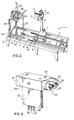
- an automatic case erector and sealer 1 of the invention is notable for its compact size and efficient construction, considering the number of operations which must take place in erecting a case from the flat state, i.e. a so-called "case flat", and gluing it in erected form.
- the magazine of flat boxes is shown at the right side of the erector and sealer 1.
- the spraying and sealing operations for the case erector and sealer 1 are housed in a hood 3, constructed of suitable metal or fibreglass.
- the hood 3 and the magazine 2 rest on a stong frame 4.
- the magazine 2 has, in effect, infinite length because it houses the cases in an edge-supported arrangement (in contrast to vertical hoppers).
- the length of the magazine 2 can be varied to hold, for example, a 1/2 hour supply or many hours supply of flat cases.
- Figure 2 illustrates a perspective view of the framework and various components of the case erector and sealer 1.
- the cases are placed on a walking track 5, which advances the horizontal stack of flat cases to the left.
- the frame 4 bearing the walking track 5 can be adjusted to accommodate different case or box lengths by a case-length adjusting handle 6.
- the frame 4 can be adjusted to accommodate various widths of boxes by a case-width adjusting handle 7.
- the walking track 5 is driven by a walking track drive 8, which, by' means of an eccentric mechanism, causes a pair of the bars of the walking track 5 to rise slightly, move forward slightly and then drop sligthly, before returning to their original position. In this way, the cases mounted on the walking track 5 are urged to move to the left slightly, so that there is always a flat case at the front of the magazine 2.
- two case injectors 9 are positioned at the front of the walking track 5. These injectors 9 drive one case upwardly on to pin and dome combinations 11, which are mounted respectively on the inside jaws of a pair of pin erector jaws 10. The bottom edges of the pin erector jaws 10 are curved upwardly to facilitate upward movement of the case on to the pin and dome combinations 11 of the two jaws 10.
- the pin erector jaws 10 are mounted on a vertical wheeled bogey 12.
- the bogey 12 by means of four circular V-grooved castors, can travel upwardly and downwardly on a V-edge vertical erector track 13.
- the pin erector jaws 10 are connected to the bogey 12 by means of parallel motion pivot bars 14.
- the minor flap front tucker 17 is shown in raised position.
- the slanted faces of the minor flap tuckers 16 and 17 cause the minor flaps of the erected case to bend inwardly and subsequently to lie flat in a horizontal position.
- major flap tuckers 18, one mounted on each side of the assembly line cause the major flaps of the erected case to bend inwardly into a partially tucked position.
- the random glue switch sequencing system 19 determines the position of the case on the apparatus and signals the glue head 20 to spray cold adhesive according to a predetermined pattern on to the inside surface of the two partially-opened major flaps of the case.
- a case compression platen 24, affixed to a case compression mast 25, is mounted above the compression plate 22 by means of support legs 23. This unit is capable of travelling upwardly and downwardly by means of mast travel wheels 26.
- the platen 24 descends into the interior of the case resting on the compression plate 22 and applies a strong force to the bottom major and minor flaps of the case, with sprayed cold adhesive therein, thereby rapidly adhering the flaps together.
- a strong force is applied to the top of the compression mast 25 by means of a high compression rocker 27 and compression booster 28.
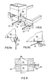
- FIG. 3 illustrates in perspective a detailed view of the glue head 20.
- the glue head 20 is constructed of a main body 29, which has mounted on its front, a pair of 360° rotating nozzle heads 30.
- a cover plate 31 is secured to the rear of the main body 29, which, with the cover plate 31, is affixed on a mounting and supply fin 32 by means of suitable screws and bolts through holes 33.
- the rotating nozzle heads 30 are each constructed with a glue jet and needle combination 34.
- a cross-blower air nozzle 35 is positioned at right-angles and close to the glue jet needle 34.
- Glue for the glue head 20 is supplied through a glue supply port 36.
- Air for the air nozzle 35 is supplied through an air port 37.
- Air required to retract the needle 34 in the glue jet 34 is supplied through an air port 38.
- Figure 4 represents, close to actual size, a side elevation view of the glue head 20, described in association with Figure 3. It should be noted that the glue head 20, as shown in Figure 4, includes an adjusting screw 40 which is located on the rear face of the cover plate 31.
- Figure 5 illustrates an end elevation view of the glue head 20, which is again shown close to actual size, as in Figure 4.
- the diminutive size of the glue head 20 and the fact that it is reliable in operation are believed to be major innovations and represent substantial advances over much larger and more cumbersome glue heads now used in case-erector and sealing lines and equipment.
- the rotating nozzle heads 30, as shown in Figure 5, are positioned so as to spray adhesive in opposite directions to one another, that is, horizontally to either side of the glue head 20.
- the cross-blower air nozzle 35 for each nozzle head 30 is carried in a rotary air nozzle body 39 for each nozzle.
- Figure 6 illustrates a cut-away view, larger than actual size, of glue head 20.
- the rotating nozzle head 30 is shown at the top of the main body 29.
- the manner in which a glue volume adjusting screw 40 fits within the cover plate 31 is readily seen.
- Extending over a substantial length within the body 29 is a needle stem 43.
- this needle stem 43 fits within a nozzle cone 42.
- the needle stem 43 can move slightly upwardly or downwardly as required to enable glue to be ejected around the circumference of the needle 43.
- the needle 43 is pointed and fits within a seat 41 in the cone 42.
- the needle stem 43 is mounted within the body 29 by means of a series of seals comprising needle stem seals 44, a brass seal retainer 45, a seal pressure spring 46, a piston 48 and a piston seal 49.
- An air chamber 47 is located above the piston 48.
- a variable spring 50 (piston return) is positioned below the piston 48 and forces it upwardly.
- Figure 7 shows the glue head spraying adhesive on the insides of the major flaps 55 of a case 54.
- the spray pattern 53 assumes a fan shape in each case.
- a further advantage of this arrangement is that the glue head 20 is confined within the partially-closed major flaps 55, so that very little of the glue escapes into the air. Thus coating-out. of the glue on surrounding equipment is minimized.
- the direction of travel of the case 54 along the line is shown by an arrow.
- Figure 8 illustrates how glue from the glue head 20 is sprayed in a fan-like pattern 53 from the pair of nozzles 34 to apply four generally square areas of adhesive 56 at four locations on the major flaps 55 of the case 54. It is important to note that the glue is applied in the four areas so that a margin is left around the circumferences of these four glue areas 56, to avoid overspray on to the exterior portions of the case or surrounding equipment.
- the timing of glue application is governed by the random glue switch 19 described in detail later in association with Figure 21.
- the random glue switch 19 is very versatile and can sense various sizes of box. By sending appropriate electrical signals, it can ensure that glue is properly sprayed at predetermined points upon the interior surfaces of the major flaps of cases as they travel along the line.
- Figure 9 represents a perspective view of the major flap turning and hold-down mechanism 18.
- the mechanism 18 comprises a pair of parallel finger-like prongs 57 extending from an axially- rotatable cylindrical base 58, which is affixed to the frame 4 immediately ahead of the case magazine section.
- the case 54 after being erected by the pin erector jaws 10 and moved over the tackers 16 and 17, is lowered with its flaps down, so that the two major flaps 55b extend downwardly between the two respective pairs of prongs 57.
- FIG. 9a The manner in which a major flap 55 extends downwardly between the pair of prongs 57 is illustrated in end elevation view in Figure 9a.
- the prongs 57 then rotate clockwise (as seen in Figure 9a) through approximately 90° (see Figure 9b), whereby the major flap 55 is turned inwardly and upwardly to an almost horizontal position.
- the prongs 57 and base 58 are rotated by an automatic rotating mechanism (not shown) mounted on the back of the plate or frame 4.
- the prongs 57 by gripping the major flaps 55 in effect, hold the case 54 down and permit the pins 64 of the jaw 10 to be pulled upwardly out of the case.
- the box pusher 15 pushes the case 54 along the apparatus over the glue section and off the prongs 57.
- FIG. 10 illustrates in detail the construction of the erector jaws 10, the pin and dome combination 11, the wheeled bogey 12 and the parallel-motion side pivot arms 14.
- the entire assembly is capable of travelling upwardly and downwardly on the vertical erector track 13 by means V-grooved castors 67.
- These castors 67 are rotationally mounted on the bogey 12 by means of four castor axles 69.
- the castors 67 travel in pairs upwardly and downwardly on the pair of V-faced tracks 68. Upward motion of the bogey 12 is stopped at a predetermined point by a pivot stop 80.
- the pair of erector jaws 10 operate in clamshell manner about a pivot point from a position where they are proximate and parallel.to one another to a position where they are at right-angles to one another (as shown in Figure 10).
- Mounted in linear series on the two respective interior faces of the pair of erector jaws 10 are a plurality of the pin and dome combinations 11. While the number of pin and dome combinations 11 can be varied as required, as shown in Figure 10, five pin and dome combinations 11 are preferably positioned in a line on the main erector jaw 10, shown at the left side of Figure 10, while three pin and dome combinations 11 are preferably positioned in a line on the right erector jaw 10.
- the two pin and dome combinations 11 mounted in the region of the erector jaw 10 remote from the pivot point have pairs of pins, while the three combinations 11 nearer to the pivot point have single pins.
- a pair of pins rather than a single pin, provides better gripping action on a case which has been opened by means of the clam-shell-like action of the pair of erector jaws 10.
- the two sides of the opened case not held by the pair of erector jaws 10 create a bending moment on the two erector jaws 10 and this moment is better handled by having pairs of pins located at the remote wings of the erector jaws 10.
- Single pins are used in the interior where the grip need not be as strong.
- Domes 61 are preferred because they guide the upper edges of the flat case easily and smoothly on to the sharp points of the needles or pins 64.
- the pins 64 are mounted in pin-retaining blocks 63, which are held on the erector jaws 10 at desired locations by retaining screws 65.
- the sharpened points of the pins 64 are hardened by known metal-hardening techniques and are carefully polished to ensure that they easily penetrate the edges of a corrugated cardboard box, without creating a substantial amount of resistance. This ensures trouble-free operation.
- Relative orientation of the erector jaws 10 and the wheeled bogey 12 is maintained by means of a set of four parallel-motion side pivot arms 14. These arms 14 permit the erector jaws 10 to be moved from left to right and in reverse, as seen in Figure 10, and thus permit the erected case to be opened from a closed flat position and moved from right to left along the case erector and gluing line.
- the action of the pivot arms 14 is controlled by side-motion acutation dogs 71 which are located on the reverse side of the bogey 12. These dogs 71 are controlled by an actuation bar 72, which moves upwardly and downwardly.
- Figure 10a illustrates a detailed side view of the relative orientation of a pin 64 with its dome 61, as mounted on the jaw plate 10.
- the pin 64 can be removed for shaprening or replacement and is secured in the pin block 63 by means of a pin-holding screw 66.
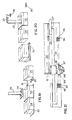
- Figure 11 illustrates in enlarged view, the manner in which the edge of a corrugated Kraft cardboard piece 73 is guided by means of a dome 61 on to the sharpened tip of a needle 62.
- a dome 61 To enable efficient operation of the case-erecting line, at high speed, it is extremely important that the edge of the corrugated board 73 of the flat case is guided precisely on to the sharpened tip of the needle 62. This is accomplished by the dome 61.
- Figure 12 illustrates in enlarged and exaggerated end elvation view the manner in which the alternating positioning of the domes 61 and pins 62, on the respective parallel opposing erector jaw faces 10, forces the edge of the corrugated cardboard 73 to be guided on to the tips of the pins 62 such that the edge of the cardboard 73 assumes a sine-wave pattern.
- This sine-wave pattern in combination with the action of the plurality of domes 61, ensures that the edge of the corrugated cardboard 73 is injected on to the sharp tips of all of the plurality of pins 62. This ensures that the cardboard edge does not miss the hardened points or is skewered only by some of the pins.
- the alternating dome and pin design permits various thicknesses of cardboard 73 to be handled by the pin 62 and dome 61 combination. This is done by the clearance 74 between the pin 62 and the face of the opposite erector jaw 10.
- Figure 13 reflects the prior art and illustrates the number of steps required in order to glue a case using conventional case-gluing equipment. Using such equipment, it is necessary for the case to travel through four case (box) lengths before the major and minor flaps of the case can be compression sealed. Furthermore, the process is energy-consumptive, not only because the case must pass through four case lengths in order to be glued, but also the major flaps of the case must be folded, completely opened and closed during the sequence.
- Figure 14 shows the marked contrast in distance, time and technique possible with the case gluing system of this invention, when compared to the conventional method illustrated in Figure 13.
- An important distinction is that the major flaps of the case, in the process of the invention, need not be fully opened and closed in order to be glued. This is because of the unprecedented diminutive size of the glue head 20 (which heretofore was not thought possible), and the extremely efficient glue-spraying pattern which can be created by this glue head 20.
- the walker bar 5 continually moves the flat cases (blanks) so that the front case (the left-most case) abuts the case injector 9.
- an injector cylinder 75 upon automatic command, this injects a single flat case upwardly into the space between the two parallel erector jaws 10 and on to the pins mounted between the two jaw faces (as seen in enlarged detail in Figure 12).
- the pair of erector jaws 10 by means of the parallel motion pivot bars 14, move the case or box and themselves away from the magazine 2 of the cases 76 and, at the same time, they open to a point where they are at right-angles to one another. In this manner, the case is simultaneously moved away from the magazine of flat cases 76 and is opened onto a rectangular orientation (when viewed from above or below) to a point where the opened case 54 is positioned immediately above the minor flap tuckers 16 and 17.
- the fold-down front minor flap tucker 17 is raised upon command by means of an air cylinder 78 and, subsequently, when the case 54 is moved down the line, the air cylinder 78 operates to pull the flap tucker 17 downwardly to a horizontal position, thereby enabling the case 54 to pass over it (see Figure 17).
- the case 54 As seen in Figure 17, the case 54, by means of the bogey 12 which travels downwardly on the vertical erector track 13, descends upon the minor flap tuckers 16 and 17, so as to fold the two minor flaps of the case 54 inwardly and upwardly. Then, as seen in Figure 18, the pair of rotatable major flap tuckers 18, with the prongs 57, grip the major flaps 55 on either side of the case 54. The two pairs of prongs 57 rotate and tuck the two major flaps 55 of the case inwardly and slightly upwardly to a point where the major flaps are within approximately 30 degrees of being completely folded horizontally against the bottom of the case 54.
- the glue head 20 is shown as spraying adhesive in a fan-like pattern laterally to either side from two nozzles.
- adhesive is not sprayed by the glue head 20 until it is completely housed within the major flaps 55 of the case 54. This ensures that adhesive will not be sprayed at large on to surrounding equipment.
- Timing of the spray of adhesive from the glue head 20 on to the interior surfaces of the major and minor flaps is determined by the random glue switch 19, which by means of sensors detects the leading edge of the case 54, permits it to proceed along the line a small further distance, and then signals the glue head 20 and its air supply to spray adhesive inside the two major flaps.
- the preferred adhesive pattern is four separate rectangular patches of glue on the major and minor flaps, as illustrated and discussed previously in association with Figure 8.
- the two major flaps 55 of the case 54 are closed to a horizontal position by pushing the case 54 further to a position where it rests on the compression plate 22. At this point, the case 54 is directly under the compression platen 24. Also, the case 54 is held between two parallel side mounted endless alignment belts 21 (see Figure 2).
- the compression platen 24, by means of a vertical ram 25, is moved downwardly in the case 54 to a point where it touches the upper surfaces of the two minor bottom flaps.
- high pressure is applied to the top of the ram 25 by means of the booster cylinder 28, which acts through the rocker arm 27. This high pressure forces the interfaces of the major and minor flaps of the case 54 tightly together and ensures that the flaps are glued securely together.
- the ram 25 moves upwardly to a point where the compression platen 24 is withdrawn above the upper regions of the case 54.
- the case 54 is then moved further down the line to a point where it is pulled away by means of an outfeed belt 79.
- the case 54 can be filled with appropriate consumer items, such as cans or bottles.
- Figure 21 illustrates in side elevation view a detail of the random glue switch sequencer 19, which automatically determines the leading and trailing edges of the case 54 and regulates the turning on and off of the air and glue supplies to the glue head 20.
- a wheeled bogey 81 rides on a central track 82 and is located and oriented with the box pusher 15.
- a front air switch 83 and a front glue switch 84 are mounted on a carrier connected to the case magazine rack 76.
- a back blowing air switch 85 and a back glue switch 86 are mounted on a second support affixed to the compression plate 22.
- the wheeled bogey 81 carries a glue carrier 87 which has thereon a glue cam 88 and an air cam 89.
- the leading edge of the magazine location is determined by the adjustment position of the box length adjusting handle 6. This determines the location of the front air switch 83 and the front glue switch 84.
- the distance between the front switches 83 and 84 and the back switches 85 and 86 is related to the length of the case 54.
- the air cam 89 and glue cam 88 which move in unison with the box pusher 15, first contact respectively the switches 83 and 84, which in turn, by electrical signals, cause the glue head 20 to spray adhesive on the flaps 55 of the case 54.
- the length of adhesive spray time is proportionately determined by the length of the glue cam 88 and the air cam 89. A longer length means a longer spray time, and vice versa.
- the glue cam carrier 87 during its travel along the track 82, after contacting the switches 83 and 84, covers a distance where the cams contact no switches. Then, after travelling over this region, the carrier 87 approaches the compression plate 22, whereupon the cams 88 and 89 contact the back blowing air switch 85 and the back glue switch 86. This contact causes a second application of adhesive by the glue head 20 to a second area of the flaps 55 (see Figure 8).
- the glue spray actuation mechanism starts prior to the air flow and ceases prior to the air being turned off, which assists in keeping the glue head 20 clean and functioning efficiently.
- the carrier 87 illustrated in Figure 21 shows different lengths of cams above one another.
- the carrier 87 can be adjusted upwardly or downwardly in order to expose various lengths of cams to the air and glue switches, thereby regulating as required the length of the adhesive spray time.
- the cam length can be varied by constructing the cams in two parallel strips which can be moved relative to one another, thereby in effect providing a longer or shorter cam length, as required.
- the switches 83, 84, 85 and 86 can be inactivated, or the carrier 82 can be drawn back, on return of the carrier 87 to its original position, thereby preventing the spraying of adhesive from the glue head 20 when it is not wanted.
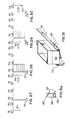
- FIGs 22 to 30 illustrate the construction and sequential operation of an alternative type of random glue switch sequencer 19.
- this other form of random glue switch sequencer 19 comprises four electrical switches 91, 92, 93 and 94, arranged in a line parallel and adjacent to the path travelled by a case to be glued (indicated by the two double-headed arrows).
- the four switches have four respective contact sensors 95, 86, 97 and 98.
- Each switch is connected in series to an electrical power supply 99 according to the circuit diagram shown in Figure 22.
- the switches 91 to 94 are also connected to a solenoid-actuated air valve 90 which in turn delivers compressed air to the glue head 20 and causes it to spray glue as required.
- the case 54 As may be seen in sequence in Figures 23 to 30, the case 54, as it travels along the line as indicated by the arrow, first contacts the switch 91 ( Figure 23) and then the switch 92. Contact with these two switches does not activate the solenoid-actuated air valve 90 and hence no glue is sprayed on the major flaps of the case 54. However, when the case 54 advances along the line to the point where it contacts the switch 93 ( Figure 25), then the valve 90 is actuated and the glue head 20 commences to spray glue on the major flaps of the case 54 (the second major flap and glue nozzle are not shown for simplicity of illustration). Glue continues to be sprayed on the case 54 until the switch 94 is contacted. Then the air valve is turned off and glue spraying stops.
- the case 54 proceeds further along the line until its end loses contact with the switch 91 ( Figure 27). This activates the valve 90 a second time and the glue head 20 commences to spray glue on the major flap of the case 54 at a second location (see the pattern shown in Figure 8).
- the glue head 20 continues to spray glue on the major flap (see Figure 28) until the rear corner of the case 54 advances to the point where it loses contact with the switch 92. This de-activates the air valve 90 and the glue head 20 stops spraying glue. The case 54 then proceeds along the line, ultimately losing contact with the switches 93 and 94 as well (see Figures 29 and 30). These two switches acivate the air valve 90 only when contacted by the leading edge of the case 54 and have no function when released by the rear edge of the case 54.
- This embodiment of the random glue switch sequencer 19 requires a between-case resetting mechanism (not shown) or a on-case length space between cases so that the sensors 85, 86, 87 and 88 can return to their original positions after being triggered.
- the contact sensors 95, 96, 97 and 98 have sufficient length of function properly, even though there may be significant variations in the widths of the cases 54 proceeding in series along the line.
- the position of the overall random glue switch sequencer 19 can be moved inwardly or outwardly, as required.
- the relative lengths and distances between the glue-sprayed areas can be adjusted as required by varying the distances between the four switches 91, 92, 93 and 94.
- Figure 31 illustrates in perspective view an alternative apparatus for holding the case 54 downwardly by means of a pair of transit bars 155 positioned overthe minor front flap tucker 17.
- the case 54 is gripped by means of hold-down strips 157, mounted on the interior sides of the two transit bars 155.
- hold-down strips 157 mounted on the interior sides of the two transit bars 155.
- This force attempts to drive the case 54 upwardly, which is detrimental to proper functioning of the line.
- This force can be resisted by means of the hold-down strips 157, which, in association with the retaining or transit bars 155, are mounted in a self- correcting manner about a pivot point 158.
- the retaining transit bars 155, together with the hold-down strips 157 can be moved unwardly or outwardly in a lateral direction from each side of the case 54. This can be done by actuator bars or some other acceptable and known technique.
- one of the major flaps 55 is shown in a vertically downward orientation. This is for illustrative purposes only. In operation, the two major flaps are bent inwardly by the fingers of the major flap tuckers and the hold-downs 155 which pivotally rotate inwardly and upwardly as required.
- Figure 31a shows in detail the way in which the pair of hold-down strips 157 are mounted within the retaining bar 155 by means of rubber retaining rings 160.
- a mechanical system has been devised which takes advantage of this discovery and puts it to practical use.
- the system is basically designed for gluing together the flaps of boxes, cartons or cases erected from the flat state and used as packaging for articles such as cans or bottles.
- the system compresses tightly together the bottom of a partially-assembled corrugated cardboard box, including the flaps, by using a primary compression plate system with a secondary booster system.
- the key to the invention is the discovery and recognition that it is possible to adhere two pieces of pressed fibrous material together, such as corrugated cardboard, using a cold-cure adhesive, in a matter of only 0.25 to 1.5 seconds by using a combination of high pressure and a thinly-spread atomized pattern of adhesive discretely broadcast over one or both of the interface surfaces to be glued together in a parallel manner. While a pressure within a broad range may suffice, it has been found that a pressure in the range from 1.4 to 11.2 kg/cm 2 , (namely 20 to 1601bs per sq. in) gives good results.
- the items in erected form are around 25 to 75 cm (10-30 inches) in depth. Furthermore, the boxes, cases or cartons are travelling along the line at a rate of 20 to 40 boxes per minute. These rates allow only short manipulation times for each box, ranging from 1 to 3 seconds.
- the high pressure applicator in order to accomplish an operation, such as the sealing of the bottom flaps of a box, it is necessary for the high pressure applicator to descend rapidly into the interior of the box for a distance of at least 25 to 75 cm (10 to 30 inches) to a position nearthe bottom of the box and then, at the end of the stroke, to apply a pressure of 1.4 to 11.2 kg/cm 2 (20 to 160 Ibs per sq in) to the bottom of the box.
- the pressure applied will vary according to process conditions and requirements. These conditions present a difficult operational problem, because the pressure applicator not only has to travel at substantial speeds, but it must be heavy and strong enough (which creates an unwanted high inertia coefficient) to generate a substantial force at the end of each stroke.
- a secondary booster system which operates in the following manner. After the lightweight pressure applicator descends rapidly into the interior of the corrugated box by 25 to 75 cm (10 to 30 inches) as required, a secondary pressure booster system comes into play and applies 1.4 to 11.2 kg/cm 2 (20 to 160 Ibs sq in) of pressure for the last 3 mm (1/8 inch) stroke of the pressure applicator. This system is described in more detail below in association with Figures 32 to 34 of the accompanying drawings.
- FIG 32 two parallel horizontal pieces of corrugated cardboard 201 and 202 are shown separated from one another.
- An atomized dot-like pattern of discrete particles of liquid or emulsified cold-cure adhesive 203 has been applied over the the top surface of the bottom piece of cardboard 202.
- the adhesive 203 can be applied by any suitable adhesive applicator nozzle. However, it is highly important that the adhesive is sprayed over the surface in a thin pattern of tiny discrete particles and not as large drops or globules. If required or desirable, adhesive can also be sprayed on the under surface of the top piece of cardboard 201.
- a pressure applicator 204 Positioned above the upper piece of cardboard 201 is a pressure applicator 204, which consists of a horizontal broad and flat compression platen 205 constructed of steel or other suitably strong material.
- the platen 205 is controlled by a vertical cam bar 206, which travels upwardly or downwardly through a vertical stroke, as required.
- the platen 205 is reinforced by a support 207 at the point where it meets the ram bar 206.
- Figure 33 depicts, in side elevation view, the position of the applicator 204 before it descends to the bottom of its travel to press the cardboard pieces 201 and 202 together in parallel fashion.
- the upward and downward movement of the bar 206 is controlled by an air cylinder 208, which operates at 4.2 to 7.0 kg/cm 2 (60 to 100 Ibs per sq in) pressure and extends a rod 209 from an upper position, as shown in Figure 33, to a lower position as shown in Figure 34.
- the rod 209 is connected to the bar 206 by an attachment 210.
- the air cylinder 208 is capable of moving the platen 205 from its top position (as shown in Figure 33) to its bottom position, and in reverse, in rapid succession. This action enables the platen 205 to be moved upwardly and downwardly into and out of the interiors of corrugated cardboard boxes travelling along lines which erect and assemble 20 to 30 boxes per minute.
- the final pressure of the order of 1.4 to 11.2 kg/cm 2 (20 to 160 Ibs per sq in), over the last 3 mm (1/8 inch) of travel of the applicator 204, is provided by a high-compression hammer 210 and a high-compression booster cylinder 211 in combination.
- a booster force is applied to the top of the ram bar 206 by the hammer 210 which is activated by the booster cylinder 211.
- the booster hammer 210 pivots about a horizontal pivot 212 or similar device.
- the cylinder 211 automatically becomes activated at the bottom of the stroke of the pressure applicator 204 by means of a ram bar hammer advance knob 213 contacting an advance crank 214 (see Figure 34) to provide a stong solid force generating 1.4 to 11.2 kg/cm 2 (20 to 160 Ibs per sq in), to the top of the bar 206.
- the action of the hammer 210 on the top of the bar 206 causes the applicator 204 to travel approximately 3 mm (1/8 inch) further at the bottom of its stroke, thereby firmly pressing together the cardboard pieces 201 and 202 and the discrete interface of the cold-cure adhesive.
- the booster pressure can typically be 1/2 to 2 seconds in duration, or longer or shorter, as required to meet process requirements.
- the hammer 210 at the bottom of the stroke by means of contact of the knob 213 with the crank 214, rotates slightly to the right about the pivot 215, so that its right end is over the bar 206 : While it is not shown, the air cylinder 208, the air cylinder 211 and the pivot 215 are secured to a frame for solid support. Ths sides of this case can be held by a suitable hold-down mechanism such as mechanical flap-clutching fingers, side clamps or transit bars 216, as shown.
- liquid polyvinyl acetate cold-cure resin adhesive is satisfactory for the purposes of this invention. Maximum adhesion strength, following initial adhesion, is obtained within the next 5 to 10 seconds.
- the adhesion provided by a liquid cold-cure adhesive is substantially superior to a hot-melt adhesive system and, unlike a hot-melt adhesive system, is so strong upon ultimate cure that the cardboard itself will part, before the adhesive will part.
- a distinct advantage of the secondary high pressure booster step is that it saves energy and cuts down on equipment costs by eliminating heavy equipment capable of applying and transmitting high pressure throughout the entire operation cycle. High pressure is applied only at the last critical portion of the stroke cycle of the pressure applicator 204 and thus enables a lighter construction of apparatus to be used.
- a compressed air system is believed to be the preferred system for driving the various components of the apparatus.
- a hydraulic oil system is not satisfactory for line speeds as described, because such a system is too slow.
- air is clean whereas oil tends to leak from time to time and provides a hygiene problem which is not accepted in many packaging environments such as food packaging.
- the upper line displays the amount of fibre tear using a light dense spray of droplets, while the lower line displays the amount of fibre tear using a heavy atomised spray of droplets.
- the graph is based on 1.5 seconds of compression time. Beyond this time, further compression does not appear- to influence adhesive droplet penetration. Therefore, adhesive curing time starts no later than 1.5 seconds.
- Fibre tear testing was caculated 1.0 second after 1.5 seconds of compression time.
- the graph displays the correct percentage of fibre tear for 1.5 seconds of compression.
- Reactivation of dried adhesive using forms of water application has also been found to result in usable bonding when subjected to high compression techniques according to the invention.
Landscapes
- Package Closures (AREA)
- Making Paper Articles (AREA)
Description
- This invention is directed to a case erecting and sealing apparatus useful in erecting packaging cases, boxes and cartons from flat cases, sealing the minor and major flaps of the erected cases with adhesive and applying compression for securing the major and minor flaps, so that the case, box or other carton so formed can be subsequently filled with various types of consumer goods.
- In carrying out this invention, use is preferably made of a particular high-speed liquid cold adhesive curing process, described in more detail below and useful in the assembly and fastening together of two fibrous surfaces, such as the surfaces of corrugated Kraft paper cardboard boxes.
- Automatic case erector and sealing methods and apparatus now available commercially, in order to cope with box speeds of 20 to 40 per minute, are of appreciable size in length and so are space-consuming and also are generally complicated and expensive to operate. Known methods and apparatus only use hot-melt adhesives for sealing the erected boxes. Case erecting and sealing systems now available and in use suffer particularly from a number of specific disadvantages which are discussed in some detail below.
- Hot-melt adhesives are much more expensive than and not as strong as cold-cure adhesives. Long case erector and sealer lines are expensive, because they take up large amounts of expensive and valuable heated and weather- protected space.
- The apparatus currently available is generally of high cost, complicated to operate, subject to frequent breakdown and expensive in maintenance costs.
- The suction cups used in conventional apparatus are liable to lose suction due to uneven case surfaces, score or crease lines, slots, dust pick-up and debris which may be found in any normal case-erecting environment.
- Suction cup case-erecting systems used in conventional case-erecting equipment are somewhat delicate to operate and do not permit the cases to be moved about rapidly. This is because the inertia inherent in a typical flat case causes the suction used to grip the flat case to be readily broken, if the case is moved quickly from a standing position and quickly returned to a standing position.
- Case-erecting systems using suction cups, because of their delicacy, frequently fail to function and case-erecting lines moving at 10 to 40 cases per minute must be shut down as soon as one case slips out of place. Following cases on the line quickly pile up and, consequently, the line must be stopped while the cases are placed back in position, all of which results in costly downtime for the case-erecting system.
- Vacuum cup grips are used in erecting flat cases, to pull both sides of the case into a convave configuration, particularly cases made of recycled cardboard, and this concave configuration tends to cause line jamming problems when the cases enter the sealing stage of the case processing line.
- The dust collected by suction cups must be filtered out of the suction system, thereby creating considerable nuisance and expense. Further, if the filters are not cleaned or changed at appropriate intervals, the suction systems lose vacuum and the line must be shut down.
- Vacuum cup case-handling lines have difficulty handling material which shows the undersirable defect known as "wash boarding" (where the corrugated cardboard core imprints through the. outer sheets) on the surfaces of cases maufactured of corrugated cardboard made of recycled Kraft paper (which tends not to be as strong as virgin Kraft paper used in North America).
- Case-erecting systems using vacuum cups cannot tolerate a substantial amount of downward or upward force on the cases. Since considerable force is required to bend under the case of major and minor flaps of an erected case, it is not uncommon for cases to break away from the suction cups when the cases are lowered on to or are struck by the flap tuckers.
- Conventional case-erecting systems, in order to secure by adhesive the major and minor flaps of the cases, must be completely opened and then completely closed, thereby necessitating lengthy case-erecting lines to carry out these operations.
- Adhesive applicator systems used in conventional case-erecting and sealing lines are heavy, bulky and expensive, cannot operate effectively in confined spaces and can only handle hot-melt adhesives at the speeds now common in case-erecting lines.
- Conventional case-erecting and sealing apparatus use substantial quantities of expensive hot-melt adhesive and consume large quantities of valuable energy in order to function.
- Conventional case-erecting lines are noisy, dusty and become adhesive-laden because of stray droplets of adhesive which miss the flaps of the cases and collect on the various pieces of equipment and, in the case of hot glue, cause stringing or webbing.
- The large distances customary with conventional case-erector and sealing lines necessitate the cases being moved through substantial distances which is energy inefficient.
- The adhesive systems used in conventional case-sealing lines tend to create rebound from the flaps on to the spray head and free floating adhesive droplets, thereby tending to clog the nozzles of the spray head and creating irregular spray patterns which cause sealing problems for the case-sealing line.
- Conventional case-erector and sealing systems require 1/2 hour to 1/2 day down time in order to set them up for a second size of case following processing of a first size of case.
- Finally, at present, no acceptable process or apparatus is commercially available for erecting corrugated cardboard boxes from the flat state and gluing the flaps together using a liquid-cold adhesive. Such boxes are used as cases for packaging various articles such as cans and the like. The reason for this absence is simple: it takes 4 to 6 seconds using conventional case-erecting and gluing systems for a cold adhesive to reach a cure stage which causes the glued components of the box to adhere together to a point where subsequent operations can be done to the case. Most commercial box or case construction lines run at a rate of 20 to 30 boxes per minute and, consequently, the 4 to 6 second cure time is not economically viable. The assembly line has to be unduly and uneconomically long in order to provide the 4 to 6 second adhesion time before each box or case can be filled or used.
- Cold-cure adhesives also are generallly not favoured because it has been believed that such adhesives cannot be applied to a surface, set and dried and then subsequently used in adhesive applications by rewetting the dried adhesive. The adhesive strength obtained in such applications has generally been found to be unsatisfactory.
- Because of the slow cure-time required for liquid cold adhesive systems, the preferred practice in corrugated box or case construction has been to use a hot-melt adhesive. Hot-melt adhesives have the advantage that they have a relatively rapid adhesive cure-time. Unfortunately, however, these adhesives have a number of serious shortcomings.
- They generally cost about two times more than cold-cure adhesives. Furthermore, the equipment required to spray and apply hot-melt adhesives costs about five times as much as cold-cure adhesive application equipment.
- A second serious disadvantage is that hot-melt adhesives have considerably lower adhesive strength than cold-cure adhesives. Hot-melt adhesives are relatively viscous and this detracts from their ability to spread in a thin discrete particulated pattern, as is required to provide a strong adhesive bond. Further, the high viscosity inhibits the hot-melt adhesive from penetrating the fibres of the corrugated cardboard and forming a strong bond.
- A third major disadvantage with hot-melt adhesives is that they tend to be brittle at low temperatures so that boxes or cases made using hot-melt adhesives are not useful in freezer environments or in winter packaging applications.
- In view of the foregoing, it can be readily understood that there is a strong commercial need for a rapid-cure cold adhesive system which can be used for gluing corrugated boxes or cases together from corrugated cardboard blanks.
- From DE-B-2500568, a case erecting and sealing apparatus is known, which comprises means for withdrawing a case in a flat state from a supply, means for gripping the case in a flat state and means for causing the gripping means to bring the case into a tubular or erected configuration.
- According to one aspect of this invention, in a case erecting and sealing apparatus of the last- mentioned kind, the gripping means comprise at least two gripping pins, means are provided for moving the case in a flat state relative to the gripping pins, so that the leading edges of two of its sides are impaled respectively upon the gripping pins, and the means comprise first and second relatively pivotally-movable and parallel supports, the two gripping pins being mounted so as to face one another on the respective first and second supports.
- The case-erecting apparatus and method of this invention desirably use a pin and dome picking or board gripping system for erecting rectangular .cases from the flat state. The pin and dome combination is far superior to the conventional suction cup system and permits cases to be handled more rapidly and surely than is now possible with conventional case-erecting lines. This pin and dome system simplifies the actual case erection method dramatically and improves its reliability.
- The method has a number of significant advantages:
- (1) The pin and dome system reliably holds the case by the pins penetrating the extreme edges of the flattened corrugated cases. This system avoids failures when the corrugated edge of the flat case is presented to the pins in damaged condition.
- (2) The domes are offset from each other, thereby causing the corrugated box to assume a snake-like (sine-wave) configuration through the domes. This enables the pins to puncture the edges of the cases reliably and to hold each flat case accurately in position as it is tensioned over the individual domes. It also enables the apparatus to deal with a reasonable range of different thicknesses of corrugated cases without adjustment.
- (3) The pin and dome system enables the rapid erection and accurate placement of a corrugated case into the forming section of a corrugated case-erecting machine. Compensation can be readily made for unsquare cases, poor quality and different thicknesses.
- (4) One adjustment of the pin and dome combination suits many sizes. However, if case sizes are particularly large, end dome sections can be added to the erector jaws to carry greater weights or greater widths.
- Major and minor flaps of the erected case are adhesively secured, preferably by means of cold adhesive, using a specially-designed spray applicator which is capable of working within confined spaces and spraying adhesive on the insides of the two major or minor flaps of the case without having to open the flaps completely, as is now required in conventional case-erecting equipment. This procedure shortens the case-erecting line by approximately two box lengths.
- The system preferably also utilizes a random glue switch apparatus which automatically determines the leading and trailing edges of cases on the line and so determines when adhesive should be applied to the interior surfaces of the flaps.
- The adhesive applicator system is based on the concept of spraying the adhesive sideways, i.e. laterally, using an adjustable and rotatable nozzle. This makes it possible to spray inside the case flap gap, typically about 35-40 mm (H inch), without minimum adhesive bouce-back on to the spray head, which bounce-back would lower the efficient operation of the spray head.
- The advantages of this system include the following:
- (1) The device eliminates approximately two case lengths in the erecting machine, by eliminating-the necessity to open the flaps of the case fully to apply adhesive to the interior surfaces of the flaps.
- (2) The device enables the adhesive to be sprayed inside the closed case flaps, thereby drammaticallly reducing the amount of free adhesive spray floating in the air. Such adhesive tends to land on non-related mechanical parts causing mechanical failure.
- (3) The glue nozzles are rotatable through 360° and thereby provide a very high degree of flexibility.
- (4) Because the air blows at right-angles to the fluid adhesive spray emission is very close proximity to one another, a wide spray pattern can be obtained by employing an acute strike angle through the spray and at the same time a high degree of tip cleanliness is possible, giving efficient clean performance and a high repeatability to the specific adhesive pattern.
- (5) The glue head can be used for case bottom sealing, top sealing or any sealing application where a consistent spray pattern of fine or variable adhesive atomization is required, at close quarters.
- According to a preferred embodiment of the invention, the means for moving the case in a flat state relative to the gripping pins comprise at least a pair of supports upon which at least a pair of sharp pointed pins are mounted on each respective support, the two supports being mutually pivotally arranged so as to be movable from a closed position, where they are parallel to one another, to a position where they are at right-angles to one another, and wherein an injector is provided, the injector being arranged to remove a flat case from the magazine of such flat cases and to force each of two of its edges on to the points of the respective pins.
- According to another preferred feature of the invention, the apparatus includes a spray nozzle for spraying liquid adhesive on to flaps of the erected cases and an air nozzle is mounted adjacent the location of emission of the adhesive from the spray nozzle and at right-angles to the direction of emission, whereby adhesive emitted from the spray nozzle is directed by air emitted from the air nozzle.
- The apparatus of the invention desirably also includes a random glue switch sequencer system, which comprises at least two switches, sensors are mounted on the switches for detecting the leading and trailing edges of errected cases and each of the switches is arranged, upon activation by the sensors, to emit an electrical signal, whereby the case, upon being moved along the apparatus, moves sensor activating means which in turn operate the sensor of the respective switch.
- A further aspect of the invention is a method of holding and erecting a rectangular case from a flat case by means of an erector mechanism, which is characterised by (a) moving the flat case so that the leading edges of two of its sides are impaled respectively upon at least two sharpened pins mounted so as to face one another on respective first and second relatively pivotally-movable and parallel supports of the erector; and (b) relatively pivotally moving the first and second supports so that the respective leading edges of the case impaled on the pins move to a position where the associated sides of the case are at right-angles to one another.
- In accordance with a preferred embodiment of the method of this invention, the interior surfaces of the major flaps and the exterior surfaces of the minor flaps of an erected case are sprayed with liquid adhesive by:
- (a) moving the leading edge of a case past first electric sensing means arranged to detect such leading edge;
- (b) moving the leading edge of the case past second electric sensing means arranged to detect such leading edge and disposed with the first electric sensing means in a path parallel to the path of movement of the case;
- (c) moving the leading edge of the case past third electric sensing means arranged to detect such leading edge and disposed with the first and second electric sensing means in a path parallel to the path of movement of the case, the third sensing means being connected to an electrical power supply so as to send, upon actuation, an electrical signal to operate a solenoid-actuated air valve which in turn actuates a liquid adhesive spray means, whereby adhesive is sprayed upon the interior surfaces of the major flaps and the exterior surfaces of the minor flaps of the case at a first location;
- (d) moving the leading edge of the case past fourth electric sensing means arranged to detect such leading edge and disposed with the first, second and third electric sensing means in a path parallel to the path of movement of the case, the fourth electric sensing means being connected to an electrical power supply so as to send, upon detecting the leading edge of the case, an electrical signal to stop operation of the air valve and further spraying of the liquid adhesive;
- (e) detecting the trailing edge of the case by means of the first electric sensing means as the case continues to move so as thereby to connect the first sensing means to an electrical power supply and send, upon actuation, an electical signal to operate the air valve which in turn causes the liquid adhesive spray means to spray adhesive on the interior surfaces of the major flaps and the external surfaces of the minor flaps of the case at a second location; and
- (f) detecting the trailing edge of the case by means of the second electric sensing means as the case continues to move so as thereby to connect the second sensing means to an electrical power supply source and send, upon actuation, an electrical signal to stop operation of the air valve and further spraying of the liquid adhesive at the second location.
- The process and apparatus of the present invention are desirably put into effect using liquid cold-cure adhesives. These cause the rapid adhering together of fibrous surfaces, such as takes place in the erection and construction of corrugated cardboard boxes and cases from corrugated cardboard flats. Useful adhesion set times can be acheived, in using the process and apparatus of the invention, and are in the range from virtually instantaneous to 1-1/2 seconds, depending upon process variables such as temperature, pressure and the type of corrugated cardboard used. Since the cold adhesive cure-time is very short, the invention can be carried out in conjunction with conventional hot-melt adhesive box erection and gluing lines. A significant advantage of this is that the overall cost of the system is about one fifth of the cost of a typical hot-melt adhesive system.
- The cold adhesive preferably used in carrying out the process and apparatus of the invention is desirably sprayed or broadcast upon the corrugated cardboard in atomized form, using adhesive spray nozzles. A thin spread-out dotted or atomized pattern of cold adhesive, distributed over the surface of the corrugated cardboard to be glued, is believed to be a requiremnet for satisfactory performance of the system under the process conditions and apparatus of our invention.
- The pressure applied in securing two surfaces together by means of adhesive, in carrying out this invention, can be in the range from 1.4 to 11.2 kg/cm2, i.e. about 20-160 Ibs per sq. in. The cold cure adhesive may be a polyvinyl acetate resin emulsion. The fibrous surfaces being adhered together are the interface surfaces of two pieces of corrugated cardboard. The duration of the compression can usefully be about 1.0 to 2.0 seconds.
- The invention can also include the use of cold-cure adhesives which are applied to a fibrous surface, allowed to set and dry and then rewetted at some later suitable time. It has been discovered that satisfactory adhesive strengths can be obtained using our system and apparatus on rewetted surfaces having previously applied and dried cold-cure adhesive thereon.
- In order that the invention may be readily understood, preferred embodiments are described below, by way of example, in conjunction with the accompanying drawings, in which:
- Figure 1 represents a perspective view of the automatic case erector and sealer;
- Figure 2 represents a perspective view of some of the components and framework of the automatic case erector and sealer;
- Figure 3 represents a perspective view of the glue head;
- Figure 4 represents a side elevation view of the glue head;
- Figure 5 represents an end elevation view of the glue head;
- Figure 6 represents a cut-away view of the internal components of the glue head;
- Figure 7 represents a perspective view of the glue head spraying adhesive on the insides of the major flaps of a case;
- Figure 8 represents a top elevation view of the major flaps of a case with adhesive sprayed thereon at four locations;
- Figure 9 represents a perspective view of the flap turning and hold-down mechanism;
- Figure 9a represents an end view of the flap turning and hold-down mechanism with a flap extending downwardly;
- Figure 9b represents an end view of the flap turning and hold-down mechanism with a flap turned inwardly and upwardly;
- Figure 10 represents a perspective view of the box erector jaws and mounting assembly;
- Figure 10a represents an end view of the case erector jaw with pin and dome combination thereon;
- Figure 11 represents a side elevation view of the pin and dome combination aligned with the end of a corrugaged cardboard piece;
- Figure 12 represents an end elevation view of a corrugated cardboard piece fitting between alternating dome and pin combinations mounted on two parallel disposed case erector jaws;
- Figure 13 represents sequential depiction of the case erecting and gluing procedures followed in a conventional case erecting line;
- Figure 14 represents sequential depiction of the case erector and gluing procedures followed in carrying out the invention;
- Figure 15 to 18 represent sequential views of the case-erecting procedure, Figure 15 representing a perspective view of the procedure by which a box in the flattened state is projected upwardly on to the pins of the erector jaws;
- Figure 16 represents a perspective view of the procedure by which the flat box is opened and moved away from the magazine by means of the erector jaws;
- Figure 17 represents a perspective view of the procedure by which the minor flaps of the case are tucked;
- Figure 18 represents a perspective view of the procedure by which the major flaps of the case are tucked;
- Figure 19 represents a perspective view of three cases on the process line, the major flaps of one case being sprayed by a glue head, the second case being moved in position under the compression platen and the third case having been moved further along the line;
- Figure 20 represents a perspective view of the procedure by which the compression platen is lowered into the interior of one erected case so as to seal together the major and minor flaps of the erected case;
- Figure 21 represents a side elevation view of an air and glue switch system with automatic case size adjustment;
- Figure 22 represents a schematic illustration of an alternative design of random glue switch with late and early skip gap timing; and
- Figures 23 to 30 represent sequentially the operation and timing of the glue switch as it is contacted by a moving case;
- Figure 31 represents a perspective view of an erected case resting upon a portion of the automatic erector and sealer;
- Figure 31a a represents an end elevation view of a transit control bar;
- Figure 32 represents a perspective view of a lower horizontal corrugated cardboard piece, with a cold cure adhesive pattern sprayed thereon, and a superimposed horizontal corrugated cardboard piece with a high-pressure applicator positioned on the top surface of the superimposed cardboard piece;
- Figure 33 represents a side elevation view of a corrugated cardboard piece (such as a case or box) and an underlying corrugated cardboard piece (such as the flaps of the box) prior to being pressed together by means of a pressure applicator (platen);
- Figure 34 represents a side elevation view of the corrugated cardbard pieces illustrated in Figure 32 pressed together by the pressure applicator;
- Figure 35 represents a graphical depiction of the relationship between percentage of fibre tear and compression exerted on a paper-adhesive- paper interface.
- As can be seen from Figure 1, an automatic case erector and
sealer 1 of the invention is notable for its compact size and efficient construction, considering the number of operations which must take place in erecting a case from the flat state, i.e. a so-called "case flat", and gluing it in erected form. The magazine of flat boxes is shown at the right side of the erector andsealer 1. The spraying and sealing operations for the case erector andsealer 1 are housed in ahood 3, constructed of suitable metal or fibreglass. Thehood 3 and themagazine 2 rest on astong frame 4. - The
magazine 2 has, in effect, infinite length because it houses the cases in an edge-supported arrangement (in contrast to vertical hoppers). Thus, the length of themagazine 2 can be varied to hold, for example, a 1/2 hour supply or many hours supply of flat cases. - Figure 2 illustrates a perspective view of the framework and various components of the case erector and
sealer 1. The cases are placed on awalking track 5, which advances the horizontal stack of flat cases to the left. - The
frame 4 bearing thewalking track 5 can be adjusted to accommodate different case or box lengths by a case-length adjusting handle 6. Theframe 4 can be adusted to accommodate various widths of boxes by a case-width adjusting handle 7. - The
walking track 5 is driven by awalking track drive 8, which, by' means of an eccentric mechanism, causes a pair of the bars of thewalking track 5 to rise slightly, move forward slightly and then drop sligthly, before returning to their original position. In this way, the cases mounted on thewalking track 5 are urged to move to the left slightly, so that there is always a flat case at the front of themagazine 2. - At the front of the
walking track 5, twocase injectors 9 are positioned. Theseinjectors 9 drive one case upwardly on to pin and dome combinations 11, which are mounted respectively on the inside jaws of a pair ofpin erector jaws 10. The bottom edges of thepin erector jaws 10 are curved upwardly to facilitate upward movement of the case on to the pin and dome combinations 11 of the twojaws 10. - The
pin erector jaws 10 are mounted on a verticalwheeled bogey 12. Thebogey 12, by means of four circular V-grooved castors, can travel upwardly and downwardly on a V-edgevertical erector track 13. Thepin erector jaws 10 are connected to thebogey 12 by means of parallel motion pivot bars 14. - Once a flat case has been injected rapidly upwardly on to the pins of the erector jaws 10 (in closed parallel position), thereby forcing the top edges of the flat case on to the pins, the two
jaws 10 open, so that rather than being parallel to one another, they are oriented at right-angles to one another. In doing this, they open out the flat case into a rectangular shape (as seen from the top). The opened case is shifted forwardly by the opening motion of theerector jaws 10 to a point where it can be lowered on to a minor case flaprear tucker 16 and a minor caseflap front tucker 17. The open case is then lowered by thewheeled bogey 12 running down thevertical erector track 13. - In Figure 2, the minor
flap front tucker 17 is shown in raised position. The slanted faces of the minor flap tuckers 16 and 17 cause the minor flaps of the erected case to bend inwardly and subsequently to lie flat in a horizontal position. Shortly thereafter, major flap tuckers 18, one mounted on each side of the assembly line, cause the major flaps of the erected case to bend inwardly into a partially tucked position. Then, the minorflap front tucker 17, being pivotally mounted, pivots downwardly to a horizontal position, to permit acase transit pusher 15 to push the case forwardly (to the left) over aglue head 20. - Not shown in Figure 2 is the random glue
switch sequencing system 19, described in more detail later in association with figure 21. The randomglue switch system 19 determines the position of the case on the apparatus and signals theglue head 20 to spray cold adhesive according to a predetermined pattern on to the inside surface of the two partially-opened major flaps of the case. - Once the adhesive has been applied, the case is pushed forwardly (to the left) so that the major flaps move off the hold-down
fingers 18 and on to acompression plate 22, betweenendless alignment belts 21. Acase compression platen 24, affixed to acase compression mast 25, is mounted above thecompression plate 22 by means ofsupport legs 23. This unit is capable of travelling upwardly and downwardly by means ofmast travel wheels 26. Theplaten 24 descends into the interior of the case resting on thecompression plate 22 and applies a strong force to the bottom major and minor flaps of the case, with sprayed cold adhesive therein, thereby rapidly adhering the flaps together. A strong force is applied to the top of thecompression mast 25 by means of ahigh compression rocker 27 andcompression booster 28. - Figure 3 illustrates in perspective a detailed view of the
glue head 20. Theglue head 20 is constructed of amain body 29, which has mounted on its front, a pair of 360° rotating nozzle heads 30. Acover plate 31 is secured to the rear of themain body 29, which, with thecover plate 31, is affixed on a mounting andsupply fin 32 by means of suitable screws and bolts throughholes 33. - The rotating nozzle heads 30 are each constructed with a glue jet and
needle combination 34. Across-blower air nozzle 35 is positioned at right-angles and close to theglue jet needle 34. Glue for theglue head 20 is supplied through aglue supply port 36. Air for theair nozzle 35 is supplied through anair port 37. Air required to retract theneedle 34 in theglue jet 34 is supplied through anair port 38. - Figure 4 represents, close to actual size, a side elevation view of the
glue head 20, described in association with Figure 3. It should be noted that theglue head 20, as shown in Figure 4, includes an adjustingscrew 40 which is located on the rear face of thecover plate 31. - Figure 5 illustrates an end elevation view of the
glue head 20, which is again shown close to actual size, as in Figure 4. The diminutive size of theglue head 20 and the fact that it is reliable in operation are believed to be major innovations and represent substantial advances over much larger and more cumbersome glue heads now used in case-erector and sealing lines and equipment. The rotating nozzle heads 30, as shown in Figure 5, are positioned so as to spray adhesive in opposite directions to one another, that is, horizontally to either side of theglue head 20. Thecross-blower air nozzle 35 for eachnozzle head 30 is carried in a rotaryair nozzle body 39 for each nozzle. - Figure 6 illustrates a cut-away view, larger than actual size, of
glue head 20. Therotating nozzle head 30 is shown at the top of themain body 29. The manner in which a gluevolume adjusting screw 40 fits within thecover plate 31 is readily seen. Extending over a substantial length within thebody 29 is aneedle stem 43. At the top, this needle stem 43 fits within anozzle cone 42. The needle stem 43 can move slightly upwardly or downwardly as required to enable glue to be ejected around the circumference of theneedle 43. At the top, theneedle 43 is pointed and fits within aseat 41 in thecone 42. The needle stem 43 is mounted within thebody 29 by means of a series of seals comprising needle stem seals 44, abrass seal retainer 45, aseal pressure spring 46, apiston 48 and apiston seal 49. Anair chamber 47 is located above thepiston 48. A variable spring 50 (piston return) is positioned below thepiston 48 and forces it upwardly. - Figure 7 shows the glue head spraying adhesive on the insides of the
major flaps 55 of acase 54. Thespray pattern 53 assumes a fan shape in each case. A further advantage of this arrangement is that theglue head 20 is confined within the partially-closedmajor flaps 55, so that very little of the glue escapes into the air. Thus coating-out. of the glue on surrounding equipment is minimized. The direction of travel of thecase 54 along the line is shown by an arrow. - Figure 8 illustrates how glue from the
glue head 20 is sprayed in a fan-like pattern 53 from the pair ofnozzles 34 to apply four generally square areas of adhesive 56 at four locations on themajor flaps 55 of thecase 54. It is important to note that the glue is applied in the four areas so that a margin is left around the circumferences of these fourglue areas 56, to avoid overspray on to the exterior portions of the case or surrounding equipment. The timing of glue application is governed by therandom glue switch 19 described in detail later in association with Figure 21. Therandom glue switch 19 is very versatile and can sense various sizes of box. By sending appropriate electrical signals, it can ensure that glue is properly sprayed at predetermined points upon the interior surfaces of the major flaps of cases as they travel along the line. - Figure 9 represents a perspective view of the major flap turning and hold-
down mechanism 18. Themechanism 18 comprises a pair of parallel finger-like prongs 57 extending from an axially- rotatablecylindrical base 58, which is affixed to theframe 4 immediately ahead of the case magazine section. Thecase 54, after being erected by thepin erector jaws 10 and moved over thetackers prongs 57. - The manner in which a
major flap 55 extends downwardly between the pair ofprongs 57 is illustrated in end elevation view in Figure 9a. Theprongs 57 then rotate clockwise (as seen in Figure 9a) through approximately 90° (see Figure 9b), whereby themajor flap 55 is turned inwardly and upwardly to an almost horizontal position. Theprongs 57 andbase 58 are rotated by an automatic rotating mechanism (not shown) mounted on the back of the plate orframe 4. Theprongs 57, by gripping themajor flaps 55 in effect, hold thecase 54 down and permit thepins 64 of thejaw 10 to be pulled upwardly out of the case. After theflaps 55 have been turned inwardly and upwardly and the pins removed, thebox pusher 15 pushes thecase 54 along the apparatus over the glue section and off theprongs 57. - Figure 10 illustrates in detail the construction of the
erector jaws 10, the pin and dome combination 11, thewheeled bogey 12 and the parallel-motionside pivot arms 14. The entire assembly is capable of travelling upwardly and downwardly on thevertical erector track 13 by means V-groovedcastors 67. Thesecastors 67 are rotationally mounted on thebogey 12 by means of fourcastor axles 69. Thecastors 67 travel in pairs upwardly and downwardly on the pair of V-faced tracks 68. Upward motion of thebogey 12 is stopped at a predetermined point by apivot stop 80. - The pair of
erector jaws 10 operate in clamshell manner about a pivot point from a position where they are proximate and parallel.to one another to a position where they are at right-angles to one another (as shown in Figure 10). Mounted in linear series on the two respective interior faces of the pair oferector jaws 10 are a plurality of the pin and dome combinations 11. While the number of pin and dome combinations 11 can be varied as required, as shown in Figure 10, five pin and dome combinations 11 are preferably positioned in a line on themain erector jaw 10, shown at the left side of Figure 10, while three pin and dome combinations 11 are preferably positioned in a line on theright erector jaw 10. The two pin and dome combinations 11 mounted in the region of theerector jaw 10 remote from the pivot point have pairs of pins, while the three combinations 11 nearer to the pivot point have single pins. - A pair of pins, rather than a single pin, provides better gripping action on a case which has been opened by means of the clam-shell-like action of the pair of
erector jaws 10. The two sides of the opened case not held by the pair oferector jaws 10 create a bending moment on the twoerector jaws 10 and this moment is better handled by having pairs of pins located at the remote wings of theerector jaws 10. Single pins are used in the interior where the grip need not be as strong. -
Domes 61 are preferred because they guide the upper edges of the flat case easily and smoothly on to the sharp points of the needles or pins 64. Thepins 64 are mounted in pin-retainingblocks 63, which are held on theerector jaws 10 at desired locations by retainingscrews 65. The sharpened points of thepins 64 are hardened by known metal-hardening techniques and are carefully polished to ensure that they easily penetrate the edges of a corrugated cardboard box, without creating a substantial amount of resistance. This ensures trouble-free operation. - Relative orientation of the
erector jaws 10 and thewheeled bogey 12 is maintained by means of a set of four parallel-motionside pivot arms 14. Thesearms 14 permit theerector jaws 10 to be moved from left to right and in reverse, as seen in Figure 10, and thus permit the erected case to be opened from a closed flat position and moved from right to left along the case erector and gluing line. The action of thepivot arms 14 is controlled by side-motion acutation dogs 71 which are located on the reverse side of thebogey 12. Thesedogs 71 are controlled by anactuation bar 72, which moves upwardly and downwardly. - Figure 10a illustrates a detailed side view of the relative orientation of a
pin 64 with itsdome 61, as mounted on thejaw plate 10. Thepin 64 can be removed for shaprening or replacement and is secured in thepin block 63 by means of a pin-holdingscrew 66. - Figure 11 illustrates in enlarged view, the manner in which the edge of a corrugated
Kraft cardboard piece 73 is guided by means of adome 61 on to the sharpened tip of aneedle 62. To enable efficient operation of the case-erecting line, at high speed, it is extremely important that the edge of thecorrugated board 73 of the flat case is guided precisely on to the sharpened tip of theneedle 62. This is accomplished by thedome 61. - Figure 12 illustrates in enlarged and exaggerated end elvation view the manner in which the alternating positioning of the
domes 61 and pins 62, on the respective parallel opposing erector jaw faces 10, forces the edge of thecorrugated cardboard 73 to be guided on to the tips of thepins 62 such that the edge of thecardboard 73 assumes a sine-wave pattern. This sine-wave pattern in combination with the action of the plurality ofdomes 61, ensures that the edge of thecorrugated cardboard 73 is injected on to the sharp tips of all of the plurality ofpins 62. This ensures that the cardboard edge does not miss the hardened points or is skewered only by some of the pins. It can be seen in Figure 12 that the alternating dome and pin design permits various thicknesses ofcardboard 73 to be handled by thepin 62 anddome 61 combination. This is done by theclearance 74 between thepin 62 and the face of theopposite erector jaw 10. - Figure 13 reflects the prior art and illustrates the number of steps required in order to glue a case using conventional case-gluing equipment. Using such equipment, it is necessary for the case to travel through four case (box) lengths before the major and minor flaps of the case can be compression sealed. Furthermore, the process is energy-consumptive, not only because the case must pass through four case lengths in order to be glued, but also the major flaps of the case must be folded, completely opened and closed during the sequence.
- Figure 14 shows the marked contrast in distance, time and technique possible with the case gluing system of this invention, when compared to the conventional method illustrated in Figure 13. An important distinction is that the major flaps of the case, in the process of the invention, need not be fully opened and closed in order to be glued. This is because of the unprecedented diminutive size of the glue head 20 (which heretofore was not thought possible), and the extremely efficient glue-spraying pattern which can be created by this
glue head 20. - The method whereby a flat case is taken from a magazine, opened into a rectangular case shape, folded to tuck the underlying minor and major flaps of the case, glue-sprayed and then compression sealed is illustrated sequentially in Figures 15 to 20.
- As can be seen in Figure 15, the
walker bar 5 continually moves the flat cases (blanks) so that the front case (the left-most case) abuts thecase injector 9. By means of aninjector cylinder 75, upon automatic command, this injects a single flat case upwardly into the space between the twoparallel erector jaws 10 and on to the pins mounted between the two jaw faces (as seen in enlarged detail in Figure 12). Then, as seen in Figure 16, the pair oferector jaws 10, by means of the parallel motion pivot bars 14, move the case or box and themselves away from themagazine 2 of thecases 76 and, at the same time, they open to a point where they are at right-angles to one another. In this manner, the case is simultaneously moved away from the magazine offlat cases 76 and is opened onto a rectangular orientation (when viewed from above or below) to a point where the openedcase 54 is positioned immediately above the minor flap tuckers 16 and 17. - In Figure 16, the fold-down front
minor flap tucker 17 is raised upon command by means of anair cylinder 78 and, subsequently, when thecase 54 is moved down the line, theair cylinder 78 operates to pull theflap tucker 17 downwardly to a horizontal position, thereby enabling thecase 54 to pass over it (see Figure 17). - As seen in Figure 17, the
case 54, by means of thebogey 12 which travels downwardly on thevertical erector track 13, descends upon the minor flap tuckers 16 and 17, so as to fold the two minor flaps of thecase 54 inwardly and upwardly. Then, as seen in Figure 18, the pair of rotatable major flap tuckers 18, with theprongs 57, grip themajor flaps 55 on either side of thecase 54. The two pairs ofprongs 57 rotate and tuck the twomajor flaps 55 of the case inwardly and slightly upwardly to a point where the major flaps are within approximately 30 degrees of being completely folded horizontally against the bottom of thecase 54. At the same time, because thecase 54 is being held down by the rotatedprongs 57, the pair oferector jaws 10 and thepins 62 can be withdrawn upwardly from the top edges of thecase 54 by thebogey 12 riding upwardly on thevertical erector track 13. At this point, thebox pusher 15 comes into play and pushes thecase 54 in a leftward direction over theglue head 20. - The positioning of the
glue head 20 can better be seen in Figure in Figure 19. For illustrative purposes only, theglue head 20 is shown as spraying adhesive in a fan-like pattern laterally to either side from two nozzles. In actuality, adhesive is not sprayed by theglue head 20 until it is completely housed within themajor flaps 55 of thecase 54. This ensures that adhesive will not be sprayed at large on to surrounding equipment. Timing of the spray of adhesive from theglue head 20 on to the interior surfaces of the major and minor flaps is determined by therandom glue switch 19, which by means of sensors detects the leading edge of thecase 54, permits it to proceed along the line a small further distance, and then signals theglue head 20 and its air supply to spray adhesive inside the two major flaps. The preferred adhesive pattern is four separate rectangular patches of glue on the major and minor flaps, as illustrated and discussed previously in association with Figure 8. - After passing over the
glue head 20 and having been properly sprayed with adhesive, the twomajor flaps 55 of thecase 54 are closed to a horizontal position by pushing thecase 54 further to a position where it rests on thecompression plate 22. At this point, thecase 54 is directly under thecompression platen 24. Also, thecase 54 is held between two parallel side mounted endless alignment belts 21 (see Figure 2). - As seen in Figure 20, the
compression platen 24, by means of avertical ram 25, is moved downwardly in thecase 54 to a point where it touches the upper surfaces of the two minor bottom flaps. At this point, high pressure is applied to the top of theram 25 by means of thebooster cylinder 28, which acts through therocker arm 27. This high pressure forces the interfaces of the major and minor flaps of thecase 54 tightly together and ensures that the flaps are glued securely together. - Following the application of high pressure by means of the
compression platen 24, theram 25 moves upwardly to a point where thecompression platen 24 is withdrawn above the upper regions of thecase 54. Thecase 54 is then moved further down the line to a point where it is pulled away by means of anoutfeed belt 79. At this point, thecase 54 can be filled with appropriate consumer items, such as cans or bottles. - Figure 21 illustrates in side elevation view a detail of the random
glue switch sequencer 19, which automatically determines the leading and trailing edges of thecase 54 and regulates the turning on and off of the air and glue supplies to theglue head 20. Awheeled bogey 81 rides on acentral track 82 and is located and oriented with thebox pusher 15. Afront air switch 83 and afront glue switch 84 are mounted on a carrier connected to thecase magazine rack 76. A back blowingair switch 85 and aback glue switch 86 are mounted on a second support affixed to thecompression plate 22. Thewheeled bogey 81 carries aglue carrier 87 which has thereon aglue cam 88 and anair cam 89. - In operation, the leading edge of the magazine location is determined by the adjustment position of the box length adjusting handle 6. This determines the location of the
front air switch 83 and thefront glue switch 84. Thus, the distance between thefront switches case 54. As thecase 54 is pushed along by thebox pusher 15, theair cam 89 andglue cam 88, which move in unison with thebox pusher 15, first contact respectively theswitches glue head 20 to spray adhesive on theflaps 55 of thecase 54. The length of adhesive spray time is proportionately determined by the length of theglue cam 88 and theair cam 89. A longer length means a longer spray time, and vice versa. Theglue cam carrier 87, during its travel along thetrack 82, after contacting theswitches carrier 87 approaches thecompression plate 22, whereupon thecams air switch 85 and theback glue switch 86. This contact causes a second application of adhesive by theglue head 20 to a second area of the flaps 55 (see Figure 8). The glue spray actuation mechanism starts prior to the air flow and ceases prior to the air being turned off, which assists in keeping theglue head 20 clean and functioning efficiently. - The
carrier 87 illustrated in Figure 21 shows different lengths of cams above one another. Thecarrier 87 can be adjusted upwardly or downwardly in order to expose various lengths of cams to the air and glue switches, thereby regulating as required the length of the adhesive spray time. As an alternative to this system, the cam length can be varied by constructing the cams in two parallel strips which can be moved relative to one another, thereby in effect providing a longer or shorter cam length, as required. Theswitches carrier 82 can be drawn back, on return of thecarrier 87 to its original position, thereby preventing the spraying of adhesive from theglue head 20 when it is not wanted. - Figures 22 to 30 illustrate the construction and sequential operation of an alternative type of random
glue switch sequencer 19. Basically, this other form of randomglue switch sequencer 19 comprises fourelectrical switches respective contact sensors electrical power supply 99 according to the circuit diagram shown in Figure 22. Theswitches 91 to 94 are also connected to a solenoid-actuatedair valve 90 which in turn delivers compressed air to theglue head 20 and causes it to spray glue as required. - As may be seen in sequence in Figures 23 to 30, the
case 54, as it travels along the line as indicated by the arrow, first contacts the switch 91 (Figure 23) and then theswitch 92. Contact with these two switches does not activate the solenoid-actuatedair valve 90 and hence no glue is sprayed on the major flaps of thecase 54. However, when thecase 54 advances along the line to the point where it contacts the switch 93 (Figure 25), then thevalve 90 is actuated and theglue head 20 commences to spray glue on the major flaps of the case 54 (the second major flap and glue nozzle are not shown for simplicity of illustration). Glue continues to be sprayed on thecase 54 until theswitch 94 is contacted. Then the air valve is turned off and glue spraying stops. - The
case 54 proceeds further along the line until its end loses contact with the switch 91 (Figure 27). This activates the valve 90 a second time and theglue head 20 commences to spray glue on the major flap of thecase 54 at a second location (see the pattern shown in Figure 8). - The
glue head 20 continues to spray glue on the major flap (see Figure 28) until the rear corner of thecase 54 advances to the point where it loses contact with theswitch 92. This de-activates theair valve 90 and theglue head 20 stops spraying glue. Thecase 54 then proceeds along the line, ultimately losing contact with theswitches air valve 90 only when contacted by the leading edge of thecase 54 and have no function when released by the rear edge of thecase 54. - This embodiment of the random
glue switch sequencer 19 requires a between-case resetting mechanism (not shown) or a on-case length space between cases so that thesensors - The
contact sensors cases 54 proceeding in series along the line. To accommodate large differences in case widths, however, such as when the line is being converted from handling one width of case to handling another width of case, the position of the overall randomglue switch sequencer 19 can be moved inwardly or outwardly, as required. Further, the relative lengths and distances between the glue-sprayed areas can be adjusted as required by varying the distances between the fourswitches - Figure 31 illustrates in perspective view an alternative apparatus for holding the
case 54 downwardly by means of a pair oftransit bars 155 positioned overthe minorfront flap tucker 17. Thecase 54 is gripped by means of hold-downstrips 157, mounted on the interior sides of the two transit bars 155. As can be recognized, when the bottom major and minor flaps of the case are forced to bend inwardly, a substantial amount of upward force is exerted on thecase 54. This force attempts to drive thecase 54 upwardly, which is detrimental to proper functioning of the line. This force can be resisted by means of the hold-downstrips 157, which, in association with the retaining ortransit bars 155, are mounted in a self- correcting manner about apivot point 158. The retainingtransit bars 155, together with the hold-downstrips 157, can be moved unwardly or outwardly in a lateral direction from each side of thecase 54. This can be done by actuator bars or some other acceptable and known technique. - In Figure 31, one of the
major flaps 55 is shown in a vertically downward orientation. This is for illustrative purposes only. In operation, the two major flaps are bent inwardly by the fingers of the major flap tuckers and the hold-downs 155 which pivotally rotate inwardly and upwardly as required. - Figure 31a shows in detail the way in which the pair of hold-down
strips 157 are mounted within the retainingbar 155 by means of rubber retaining rings 160. In the development of the corrugated board box-sealing equipment, it has been discovered that two pieces of corrugated cardboard with small atomized particles of cold-cure adhesive broadcast thinly and discretely on the interface surfaces of one or both of the pieces can be rapidly set in a matter of 0.25 to 1.5 seconds, by the application of high external pressure upon the two outer faces of the two pieces of cardboard, thereby forcing the adhesive interface together. - A mechanical system has been devised which takes advantage of this discovery and puts it to practical use. The system is basically designed for gluing together the flaps of boxes, cartons or cases erected from the flat state and used as packaging for articles such as cans or bottles. The system compresses tightly together the bottom of a partially-assembled corrugated cardboard box, including the flaps, by using a primary compression plate system with a secondary booster system.
- While various mechanical systems can probably be developed and used to practice the discovery, the key to the invention is the discovery and recognition that it is possible to adhere two pieces of pressed fibrous material together, such as corrugated cardboard, using a cold-cure adhesive, in a matter of only 0.25 to 1.5 seconds by using a combination of high pressure and a thinly-spread atomized pattern of adhesive discretely broadcast over one or both of the interface surfaces to be glued together in a parallel manner. While a pressure within a broad range may suffice, it has been found that a pressure in the range from 1.4 to 11.2 kg/cm2, (namely 20 to 1601bs per sq. in) gives good results.
- In most corrugated box carton or case assembly lines, the items in erected form are around 25 to 75 cm (10-30 inches) in depth. Furthermore, the boxes, cases or cartons are travelling along the line at a rate of 20 to 40 boxes per minute. These rates allow only short manipulation times for each box, ranging from 1 to 3 seconds. Thus, in order to accomplish an operation, such as the sealing of the bottom flaps of a box, it is necessary for the high pressure applicator to descend rapidly into the interior of the box for a distance of at least 25 to 75 cm (10 to 30 inches) to a position nearthe bottom of the box and then, at the end of the stroke, to apply a pressure of 1.4 to 11.2 kg/cm2 (20 to 160 Ibs per sq in) to the bottom of the box. The pressure applied will vary according to process conditions and requirements. These conditions present a difficult operational problem, because the pressure applicator not only has to travel at substantial speeds, but it must be heavy and strong enough (which creates an unwanted high inertia coefficient) to generate a substantial force at the end of each stroke.
- To deal with these problems and to reduce weight in the high-speed pressure applicator, we have invented a secondary booster system which operates in the following manner. After the lightweight pressure applicator descends rapidly into the interior of the corrugated box by 25 to 75 cm (10 to 30 inches) as required, a secondary pressure booster system comes into play and applies 1.4 to 11.2 kg/cm2 (20 to 160 Ibs sq in) of pressure for the last 3 mm (1/8 inch) stroke of the pressure applicator. This system is described in more detail below in association with Figures 32 to 34 of the accompanying drawings.
- Referring to Figure 32, two parallel horizontal pieces of
corrugated cardboard cure adhesive 203 has been applied over the the top surface of the bottom piece ofcardboard 202. The adhesive 203 can be applied by any suitable adhesive applicator nozzle. However, it is highly important that the adhesive is sprayed over the surface in a thin pattern of tiny discrete particles and not as large drops or globules. If required or desirable, adhesive can also be sprayed on the under surface of the top piece ofcardboard 201. - Positioned above the upper piece of
cardboard 201 is apressure applicator 204, which consists of a horizontal broad andflat compression platen 205 constructed of steel or other suitably strong material. Theplaten 205 is controlled by avertical cam bar 206, which travels upwardly or downwardly through a vertical stroke, as required. Theplaten 205 is reinforced by asupport 207 at the point where it meets theram bar 206. - Figure 33 depicts, in side elevation view, the position of the
applicator 204 before it descends to the bottom of its travel to press thecardboard pieces bar 206 is controlled by anair cylinder 208, which operates at 4.2 to 7.0 kg/cm2 (60 to 100 Ibs per sq in) pressure and extends arod 209 from an upper position, as shown in Figure 33, to a lower position as shown in Figure 34. Therod 209 is connected to thebar 206 by anattachment 210. Theair cylinder 208 is capable of moving theplaten 205 from its top position (as shown in Figure 33) to its bottom position, and in reverse, in rapid succession. This action enables theplaten 205 to be moved upwardly and downwardly into and out of the interiors of corrugated cardboard boxes travelling along lines which erect and assemble 20 to 30 boxes per minute. - The final pressure, of the order of 1.4 to 11.2 kg/cm2 (20 to 160 Ibs per sq in), over the last 3 mm (1/8 inch) of travel of the
applicator 204, is provided by a high-compression hammer 210 and a high-compression booster cylinder 211 in combination. When the two pieces ofcorrugated cardboard 201 and 202 (such as the major and minor flaps of an erected case) meet one another at the region of the bottom of the stroke of the applicator 204 (as seen in Figure 34), a booster force is applied to the top of theram bar 206 by thehammer 210 which is activated by thebooster cylinder 211. Thebooster hammer 210 pivots about ahorizontal pivot 212 or similar device. Thecylinder 211 automatically becomes activated at the bottom of the stroke of thepressure applicator 204 by means of a ram barhammer advance knob 213 contacting an advance crank 214 (see Figure 34) to provide a stong solid force generating 1.4 to 11.2 kg/cm2 (20 to 160 Ibs per sq in), to the top of thebar 206. The action of thehammer 210 on the top of thebar 206 causes theapplicator 204 to travel approximately 3 mm (1/8 inch) further at the bottom of its stroke, thereby firmly pressing together thecardboard pieces - As can be seen in Figure 34, the
hammer 210 at the bottom of the stroke, by means of contact of theknob 213 with thecrank 214, rotates slightly to the right about thepivot 215, so that its right end is over thebar 206: While it is not shown, theair cylinder 208, theair cylinder 211 and thepivot 215 are secured to a frame for solid support. Ths sides of this case can be held by a suitable hold-down mechanism such as mechanical flap-clutching fingers, side clamps ortransit bars 216, as shown. - We have found that a liquid polyvinyl acetate cold-cure resin adhesive is satisfactory for the purposes of this invention. Maximum adhesion strength, following initial adhesion, is obtained within the next 5 to 10 seconds. The adhesion provided by a liquid cold-cure adhesive is substantially superior to a hot-melt adhesive system and, unlike a hot-melt adhesive system, is so strong upon ultimate cure that the cardboard itself will part, before the adhesive will part.
- A distinct advantage of the secondary high pressure booster step is that it saves energy and cuts down on equipment costs by eliminating heavy equipment capable of applying and transmitting high pressure throughout the entire operation cycle. High pressure is applied only at the last critical portion of the stroke cycle of the
pressure applicator 204 and thus enables a lighter construction of apparatus to be used. - A compressed air system is believed to be the preferred system for driving the various components of the apparatus. A hydraulic oil system is not satisfactory for line speeds as described, because such a system is too slow. Furthermore, air is clean whereas oil tends to leak from time to time and provides a hygiene problem which is not accepted in many packaging environments such as food packaging.
- Referring to Figure 35, which depicts in graphical manner the behaviour of cold-cure adhesive sprayed on to the interface of two sheets of paper, the upper line displays the amount of fibre tear using a light dense spray of droplets, while the lower line displays the amount of fibre tear using a heavy atomised spray of droplets.
- The adhesive used in the tests giving rise to the graphical data depicted in Figure 35 is available under the trade mark RESYN 33-1583 (formerly 72-1142) and has the following characteristics:
- Product type:
- Formulated emulsion cold-cure adhesive.
- Physical properties:
- Appearance: Fluid, white product
- Viscosity: Approx. 2500 mPa.s (cP)
- Solids: Approx. 56%
- pH: Approx. 4.5
- Relative Density: Approx. 1.08 (10.8 lbs/lmp Gal)
- Meets composition requirements of U.S. F.D.A.
- Regulation 121.2520 "Adhesives".
- The graph is based on 1.5 seconds of compression time. Beyond this time, further compression does not appear- to influence adhesive droplet penetration. Therefore, adhesive curing time starts no later than 1.5 seconds.
- Fibre tear testing was caculated 1.0 second after 1.5 seconds of compression time. The graph displays the correct percentage of fibre tear for 1.5 seconds of compression.
- The compression times below reflect a percentage loss of fibre tear 1.0 second after compression.
- 1.0 sec. compression-8% reduction in fibre tear
- 0.5 sec. compression-12% reduction in fibre tear
- 0.25 sec. compression-25% reduction in fibre tear
- According to tests, 100% fibre tear is achieved in tests below 11.2 kg/cm2 (160 lbs) pressure, to as low as 1.4 kg/cm2 (20ibs) pressure. This only occurs seconds after compression, for example:
- 1.5 seconds of 1.4 to 11.2 kg/cm2 (20 Ibs to 160 lbs) pressure yields 100% fibre tear after 3.0 secs.
- 1.0 second of 1.4 to 11.2 kg/cm2 (20 Ibs to 160 lbs) pressure yields 100% fibre tear after 4.0 secs.
- 0.5 second of 1.4 to 11.2 kg/cm2 (20 Ibs to 160 lbs) pressure yields 100% fibre tear after 4.0 secs.
- 0.25 second of 1.4 to 11.2 kg/cm2 (20 lbs to 160 ibs) pressure yields 100% fibre tear after 7.0 secs.
- These results, even at the 0.25 second time,' demonstrate an initial and secondary fibre tear result which can have very viable practical applications in corrugated and related paper industries.
- Reactivation of dried adhesive using forms of water application has also been found to result in usable bonding when subjected to high compression techniques according to the invention.
Claims (28)
Priority Applications (1)
| Application Number | Priority Date | Filing Date | Title |
|---|---|---|---|
| AT82301970T ATE30535T1 (en) | 1981-04-17 | 1982-04-16 | CONTAINER FORMER AND GLUING MACHINE THAT USES A FAST AND COLD CURING ADHESIVE. |
Applications Claiming Priority (4)
| Application Number | Priority Date | Filing Date | Title |
|---|---|---|---|
| US25509581A | 1981-04-17 | 1981-04-17 | |
| US255095 | 1981-04-17 | ||
| US06/255,336 US4375383A (en) | 1981-04-17 | 1981-04-17 | High speed cold adhesive curing process and apparatus therefor |
| US255336 | 1994-06-07 |
Publications (3)
| Publication Number | Publication Date |
|---|---|
| EP0063484A2 EP0063484A2 (en) | 1982-10-27 |
| EP0063484A3 EP0063484A3 (en) | 1983-08-24 |
| EP0063484B1 true EP0063484B1 (en) | 1987-11-04 |
Family
ID=26944428
Family Applications (1)
| Application Number | Title | Priority Date | Filing Date |
|---|---|---|---|
| EP82301970A Expired EP0063484B1 (en) | 1981-04-17 | 1982-04-16 | Case erector and sealer using high speed cold-cure adhesive |
Country Status (2)
| Country | Link |
|---|---|
| EP (1) | EP0063484B1 (en) |
| DE (1) | DE3277572D1 (en) |
Families Citing this family (8)
| Publication number | Priority date | Publication date | Assignee | Title |
|---|---|---|---|---|
| US6913568B2 (en) * | 2002-12-06 | 2005-07-05 | Robert Bosch Gmbh | Apparatus for removing and erecting a folding-box blank |
| ES2422956B1 (en) * | 2012-03-09 | 2014-07-15 | Tel�sforo GONZ�LEZ OLMOS | COLA COLD INJECTED UNIT |
| BE1025786B1 (en) * | 2017-12-15 | 2019-07-15 | Pattyn Packing Lines Nv | IMPROVED DEVICE FOR FORMING A BOX |
| CN108582871A (en) * | 2018-04-10 | 2018-09-28 | 东莞市欣豪印刷包装有限公司 | A semi-automatic high-efficiency forming machine for color boxes |
| CN112549646B (en) * | 2021-01-02 | 2023-02-24 | 益阳湘芬纸业包装股份有限公司 | Removal of packing carton processing usefulness glues punch-out equipment |
| CN113479402B (en) * | 2021-06-18 | 2023-02-14 | 武汉人天包装自动化技术股份有限公司 | Vertical high-speed case unpacking machine |
| CN113479401B (en) * | 2021-06-18 | 2023-01-20 | 武汉人天包装自动化技术股份有限公司 | Unpacking method of vertical high-speed unpacking machine |
| CN113978026A (en) * | 2021-11-23 | 2022-01-28 | 高友军 | A corrugated paper box forming equipment |
Family Cites Families (5)
| Publication number | Priority date | Publication date | Assignee | Title |
|---|---|---|---|---|
| US2577205A (en) * | 1946-11-20 | 1951-12-04 | Owens Corning Fiberglass Corp | Method of producing a fabric construction for reinforcing plastics and product |
| CH300320A (en) * | 1951-05-15 | 1954-07-31 | E Abel Heinrich | Device for producing a textile material from at least two lengths of material which are glued together by means of an adhesive mass. |
| GB984038A (en) * | 1963-03-08 | 1965-02-24 | Dennis Killen | Improvements relating to the combining of continuous webs together |
| DE2500568B2 (en) * | 1975-01-09 | 1978-04-20 | Carl Edelmann Gmbh, 7920 Heidenheim | Method and machine for erecting flat blanks to form cardboard packs |
| GB2052380B (en) * | 1979-06-29 | 1983-04-07 | Chromatex Inc | Laminated polypropylene fabric |
-
1982
- 1982-04-16 DE DE8282301970T patent/DE3277572D1/en not_active Expired
- 1982-04-16 EP EP82301970A patent/EP0063484B1/en not_active Expired
Also Published As
| Publication number | Publication date |
|---|---|
| DE3277572D1 (en) | 1987-12-10 |
| EP0063484A2 (en) | 1982-10-27 |
| EP0063484A3 (en) | 1983-08-24 |
Similar Documents
| Publication | Publication Date | Title |
|---|---|---|
| US4553954A (en) | Automatic case erector and sealer | |
| US4578054A (en) | Carton erection and sealing apparatus | |
| US4348853A (en) | Case opening and sealing apparatus | |
| US8177698B2 (en) | Apparatus and method for forming a container having an enhanced corner support structure | |
| US5980440A (en) | Carton forming | |
| US10118359B2 (en) | Tray forming apparatus and method | |
| US6468025B1 (en) | Blank separation method and apparatus | |
| EP0766621B1 (en) | Apparatus and method for picking and erecting carton blanks | |
| GB2093762A (en) | Forming and/or closing cartons | |
| US4289491A (en) | Apparatus for adhesively bonding a carton | |
| EP0063484A2 (en) | Case erector and sealer using high speed cold-cure adhesive | |
| US4817931A (en) | Folded leaflet and method and apparatus for making same | |
| GB2023536A (en) | Process and apparatus for erecting and sealing a collapsedcarton | |
| US4816014A (en) | Carton handle applicator | |
| US4331435A (en) | Method and apparatus for erecting a carton | |
| US4256025A (en) | Apparatus for forming a hinged carton | |
| GB2207083A (en) | Tray forming apparatus | |
| US4378080A (en) | Fluid velocity attenuating nozzle | |
| US4375383A (en) | High speed cold adhesive curing process and apparatus therefor | |
| US3511138A (en) | Box erecting devices for reducing the effect of stringing out of adhesives | |
| US20210114326A1 (en) | Machine and methods for attaching retaining web to container blank | |
| US2696612A (en) | Boxmaking machine | |
| US4875895A (en) | Buffing apparatus for book-fold carton; and method | |
| US2570146A (en) | Folding box forming machine | |
| US3709114A (en) | Container forming machine |
Legal Events
| Date | Code | Title | Description |
|---|---|---|---|
| PUAI | Public reference made under article 153(3) epc to a published international application that has entered the european phase |
Free format text: ORIGINAL CODE: 0009012 |
|
| AK | Designated contracting states |
Designated state(s): AT BE CH DE FR GB IT LI LU NL SE |
|
| PUAL | Search report despatched |
Free format text: ORIGINAL CODE: 0009013 |
|
| RHK1 | Main classification (correction) |
Ipc: B31B 5/74 |
|
| AK | Designated contracting states |
Designated state(s): AT BE CH DE FR GB IT LI LU NL SE |
|
| 17P | Request for examination filed |
Effective date: 19840206 |
|
| GRAA | (expected) grant |
Free format text: ORIGINAL CODE: 0009210 |
|
| AK | Designated contracting states |
Kind code of ref document: B1 Designated state(s): AT BE CH DE FR GB IT LI LU NL SE |
|
| PG25 | Lapsed in a contracting state [announced via postgrant information from national office to epo] |
Ref country code: LI Effective date: 19871104 Ref country code: IT Free format text: LAPSE BECAUSE OF FAILURE TO SUBMIT A TRANSLATION OF THE DESCRIPTION OR TO PAY THE FEE WITHIN THE PRESCRIBED TIME-LIMIT;WARNING: LAPSES OF ITALIAN PATENTS WITH EFFECTIVE DATE BEFORE 2007 MAY HAVE OCCURRED AT ANY TIME BEFORE 2007. THE CORRECT EFFECTIVE DATE MAY BE DIFFERENT FROM THE ONE RECORDED. Effective date: 19871104 Ref country code: CH Effective date: 19871104 Ref country code: BE Effective date: 19871104 Ref country code: AT Effective date: 19871104 |
|
| REF | Corresponds to: |
Ref document number: 30535 Country of ref document: AT Date of ref document: 19871115 Kind code of ref document: T |
|
| PG25 | Lapsed in a contracting state [announced via postgrant information from national office to epo] |
Ref country code: SE Effective date: 19871130 |
|
| REF | Corresponds to: |
Ref document number: 3277572 Country of ref document: DE Date of ref document: 19871210 |
|
| ET | Fr: translation filed | ||
| REG | Reference to a national code |
Ref country code: CH Ref legal event code: PL |
|
| PG25 | Lapsed in a contracting state [announced via postgrant information from national office to epo] |
Ref country code: LU Free format text: LAPSE BECAUSE OF NON-PAYMENT OF DUE FEES Effective date: 19880430 |
|
| PLBE | No opposition filed within time limit |
Free format text: ORIGINAL CODE: 0009261 |
|
| STAA | Information on the status of an ep patent application or granted ep patent |
Free format text: STATUS: NO OPPOSITION FILED WITHIN TIME LIMIT |
|
| 26N | No opposition filed | ||
| PGFP | Annual fee paid to national office [announced via postgrant information from national office to epo] |
Ref country code: FR Payment date: 19950330 Year of fee payment: 14 |
|
| PGFP | Annual fee paid to national office [announced via postgrant information from national office to epo] |
Ref country code: GB Payment date: 19950406 Year of fee payment: 14 |
|
| PGFP | Annual fee paid to national office [announced via postgrant information from national office to epo] |
Ref country code: NL Payment date: 19950430 Year of fee payment: 14 |
|
| PGFP | Annual fee paid to national office [announced via postgrant information from national office to epo] |
Ref country code: DE Payment date: 19950614 Year of fee payment: 14 |
|
| PG25 | Lapsed in a contracting state [announced via postgrant information from national office to epo] |
Ref country code: GB Effective date: 19960416 |
|
| PG25 | Lapsed in a contracting state [announced via postgrant information from national office to epo] |
Ref country code: NL Effective date: 19961101 |
|
| GBPC | Gb: european patent ceased through non-payment of renewal fee |
Effective date: 19960416 |
|
| PG25 | Lapsed in a contracting state [announced via postgrant information from national office to epo] |
Ref country code: FR Effective date: 19961227 |
|
| PG25 | Lapsed in a contracting state [announced via postgrant information from national office to epo] |
Ref country code: DE Effective date: 19970101 |
|
| NLV4 | Nl: lapsed or anulled due to non-payment of the annual fee |
Effective date: 19961101 |
|
| REG | Reference to a national code |
Ref country code: FR Ref legal event code: ST |