EP0063318B1 - Lufttrennung durch Freon-Kühlung mit geringem Energieverbrauch - Google Patents
Lufttrennung durch Freon-Kühlung mit geringem Energieverbrauch Download PDFInfo
- Publication number
- EP0063318B1 EP0063318B1 EP82102989A EP82102989A EP0063318B1 EP 0063318 B1 EP0063318 B1 EP 0063318B1 EP 82102989 A EP82102989 A EP 82102989A EP 82102989 A EP82102989 A EP 82102989A EP 0063318 B1 EP0063318 B1 EP 0063318B1
- Authority
- EP
- European Patent Office
- Prior art keywords
- air stream
- stream
- heat exchanger
- cooled
- air
- Prior art date
- Legal status (The legal status is an assumption and is not a legal conclusion. Google has not performed a legal analysis and makes no representation as to the accuracy of the status listed.)
- Expired
Links
- 238000005057 refrigeration Methods 0.000 title claims abstract description 31
- 238000000926 separation method Methods 0.000 title claims abstract description 24
- IJGRMHOSHXDMSA-UHFFFAOYSA-N Atomic nitrogen Chemical compound N#N IJGRMHOSHXDMSA-UHFFFAOYSA-N 0.000 claims abstract description 44
- 229910052757 nitrogen Inorganic materials 0.000 claims abstract description 22
- 238000009434 installation Methods 0.000 claims abstract description 21
- 239000007788 liquid Substances 0.000 claims abstract description 17
- MYMOFIZGZYHOMD-UHFFFAOYSA-N Dioxygen Chemical compound O=O MYMOFIZGZYHOMD-UHFFFAOYSA-N 0.000 claims abstract description 16
- 238000000034 method Methods 0.000 claims abstract description 13
- 238000004064 recycling Methods 0.000 claims abstract description 5
- 238000004821 distillation Methods 0.000 claims description 26
- 238000001816 cooling Methods 0.000 claims description 14
- XLYOFNOQVPJJNP-UHFFFAOYSA-N water Substances O XLYOFNOQVPJJNP-UHFFFAOYSA-N 0.000 claims description 8
- CURLTUGMZLYLDI-UHFFFAOYSA-N Carbon dioxide Chemical compound O=C=O CURLTUGMZLYLDI-UHFFFAOYSA-N 0.000 claims description 6
- 239000012263 liquid product Substances 0.000 claims description 6
- 229910002092 carbon dioxide Inorganic materials 0.000 claims description 3
- 239000001569 carbon dioxide Substances 0.000 claims description 3
- 229930195733 hydrocarbon Natural products 0.000 claims description 3
- 150000002430 hydrocarbons Chemical class 0.000 claims description 3
- VUZPPFZMUPKLLV-UHFFFAOYSA-N methane;hydrate Chemical compound C.O VUZPPFZMUPKLLV-UHFFFAOYSA-N 0.000 claims description 2
- 238000011084 recovery Methods 0.000 claims 1
- 239000002808 molecular sieve Substances 0.000 description 5
- URGAHOPLAPQHLN-UHFFFAOYSA-N sodium aluminosilicate Chemical compound [Na+].[Al+3].[O-][Si]([O-])=O.[O-][Si]([O-])=O URGAHOPLAPQHLN-UHFFFAOYSA-N 0.000 description 5
- 239000000306 component Substances 0.000 description 4
- 239000007789 gas Substances 0.000 description 4
- 239000000047 product Substances 0.000 description 4
- 238000011144 upstream manufacturing Methods 0.000 description 4
- QVGXLLKOCUKJST-UHFFFAOYSA-N atomic oxygen Chemical compound [O] QVGXLLKOCUKJST-UHFFFAOYSA-N 0.000 description 3
- 239000012535 impurity Substances 0.000 description 3
- 239000001301 oxygen Substances 0.000 description 3
- 229910052760 oxygen Inorganic materials 0.000 description 3
- 238000010992 reflux Methods 0.000 description 3
- 238000007906 compression Methods 0.000 description 2
- 230000006835 compression Effects 0.000 description 2
- 238000002955 isolation Methods 0.000 description 2
- 238000004519 manufacturing process Methods 0.000 description 2
- 239000000203 mixture Substances 0.000 description 2
- 230000007420 reactivation Effects 0.000 description 2
- 238000003860 storage Methods 0.000 description 2
- 239000002699 waste material Substances 0.000 description 2
- 239000006096 absorbing agent Substances 0.000 description 1
- 238000003889 chemical engineering Methods 0.000 description 1
- 239000000498 cooling water Substances 0.000 description 1
- 125000004122 cyclic group Chemical group 0.000 description 1
- 230000009977 dual effect Effects 0.000 description 1
- 239000000428 dust Substances 0.000 description 1
- 230000008030 elimination Effects 0.000 description 1
- 238000003379 elimination reaction Methods 0.000 description 1
- 239000012530 fluid Substances 0.000 description 1
- 238000011010 flushing procedure Methods 0.000 description 1
- 239000000463 material Substances 0.000 description 1
- 238000012986 modification Methods 0.000 description 1
- 230000004048 modification Effects 0.000 description 1
- 239000013618 particulate matter Substances 0.000 description 1
- 238000005549 size reduction Methods 0.000 description 1
- 230000000153 supplemental effect Effects 0.000 description 1
Images


Classifications
-
- F—MECHANICAL ENGINEERING; LIGHTING; HEATING; WEAPONS; BLASTING
- F25—REFRIGERATION OR COOLING; COMBINED HEATING AND REFRIGERATION SYSTEMS; HEAT PUMP SYSTEMS; MANUFACTURE OR STORAGE OF ICE; LIQUEFACTION SOLIDIFICATION OF GASES
- F25J—LIQUEFACTION, SOLIDIFICATION OR SEPARATION OF GASES OR GASEOUS OR LIQUEFIED GASEOUS MIXTURES BY PRESSURE AND COLD TREATMENT OR BY BRINGING THEM INTO THE SUPERCRITICAL STATE
- F25J3/00—Processes or apparatus for separating the constituents of gaseous or liquefied gaseous mixtures involving the use of liquefaction or solidification
- F25J3/02—Processes or apparatus for separating the constituents of gaseous or liquefied gaseous mixtures involving the use of liquefaction or solidification by rectification, i.e. by continuous interchange of heat and material between a vapour stream and a liquid stream
- F25J3/04—Processes or apparatus for separating the constituents of gaseous or liquefied gaseous mixtures involving the use of liquefaction or solidification by rectification, i.e. by continuous interchange of heat and material between a vapour stream and a liquid stream for air
- F25J3/04006—Providing pressurised feed air or process streams within or from the air fractionation unit
- F25J3/04109—Arrangements of compressors and /or their drivers
- F25J3/04139—Combination of different types of drivers mechanically coupled to the same compressor, possibly split on multiple compressor casings
-
- F—MECHANICAL ENGINEERING; LIGHTING; HEATING; WEAPONS; BLASTING
- F25—REFRIGERATION OR COOLING; COMBINED HEATING AND REFRIGERATION SYSTEMS; HEAT PUMP SYSTEMS; MANUFACTURE OR STORAGE OF ICE; LIQUEFACTION SOLIDIFICATION OF GASES
- F25J—LIQUEFACTION, SOLIDIFICATION OR SEPARATION OF GASES OR GASEOUS OR LIQUEFIED GASEOUS MIXTURES BY PRESSURE AND COLD TREATMENT OR BY BRINGING THEM INTO THE SUPERCRITICAL STATE
- F25J3/00—Processes or apparatus for separating the constituents of gaseous or liquefied gaseous mixtures involving the use of liquefaction or solidification
- F25J3/02—Processes or apparatus for separating the constituents of gaseous or liquefied gaseous mixtures involving the use of liquefaction or solidification by rectification, i.e. by continuous interchange of heat and material between a vapour stream and a liquid stream
- F25J3/04—Processes or apparatus for separating the constituents of gaseous or liquefied gaseous mixtures involving the use of liquefaction or solidification by rectification, i.e. by continuous interchange of heat and material between a vapour stream and a liquid stream for air
- F25J3/04006—Providing pressurised feed air or process streams within or from the air fractionation unit
- F25J3/04012—Providing pressurised feed air or process streams within or from the air fractionation unit by compression of warm gaseous streams; details of intake or interstage cooling
- F25J3/04018—Providing pressurised feed air or process streams within or from the air fractionation unit by compression of warm gaseous streams; details of intake or interstage cooling of main feed air
-
- F—MECHANICAL ENGINEERING; LIGHTING; HEATING; WEAPONS; BLASTING
- F25—REFRIGERATION OR COOLING; COMBINED HEATING AND REFRIGERATION SYSTEMS; HEAT PUMP SYSTEMS; MANUFACTURE OR STORAGE OF ICE; LIQUEFACTION SOLIDIFICATION OF GASES
- F25J—LIQUEFACTION, SOLIDIFICATION OR SEPARATION OF GASES OR GASEOUS OR LIQUEFIED GASEOUS MIXTURES BY PRESSURE AND COLD TREATMENT OR BY BRINGING THEM INTO THE SUPERCRITICAL STATE
- F25J3/00—Processes or apparatus for separating the constituents of gaseous or liquefied gaseous mixtures involving the use of liquefaction or solidification
- F25J3/02—Processes or apparatus for separating the constituents of gaseous or liquefied gaseous mixtures involving the use of liquefaction or solidification by rectification, i.e. by continuous interchange of heat and material between a vapour stream and a liquid stream
- F25J3/04—Processes or apparatus for separating the constituents of gaseous or liquefied gaseous mixtures involving the use of liquefaction or solidification by rectification, i.e. by continuous interchange of heat and material between a vapour stream and a liquid stream for air
- F25J3/04006—Providing pressurised feed air or process streams within or from the air fractionation unit
- F25J3/04012—Providing pressurised feed air or process streams within or from the air fractionation unit by compression of warm gaseous streams; details of intake or interstage cooling
- F25J3/04024—Providing pressurised feed air or process streams within or from the air fractionation unit by compression of warm gaseous streams; details of intake or interstage cooling of purified feed air, so-called boosted air
-
- F—MECHANICAL ENGINEERING; LIGHTING; HEATING; WEAPONS; BLASTING
- F25—REFRIGERATION OR COOLING; COMBINED HEATING AND REFRIGERATION SYSTEMS; HEAT PUMP SYSTEMS; MANUFACTURE OR STORAGE OF ICE; LIQUEFACTION SOLIDIFICATION OF GASES
- F25J—LIQUEFACTION, SOLIDIFICATION OR SEPARATION OF GASES OR GASEOUS OR LIQUEFIED GASEOUS MIXTURES BY PRESSURE AND COLD TREATMENT OR BY BRINGING THEM INTO THE SUPERCRITICAL STATE
- F25J3/00—Processes or apparatus for separating the constituents of gaseous or liquefied gaseous mixtures involving the use of liquefaction or solidification
- F25J3/02—Processes or apparatus for separating the constituents of gaseous or liquefied gaseous mixtures involving the use of liquefaction or solidification by rectification, i.e. by continuous interchange of heat and material between a vapour stream and a liquid stream
- F25J3/04—Processes or apparatus for separating the constituents of gaseous or liquefied gaseous mixtures involving the use of liquefaction or solidification by rectification, i.e. by continuous interchange of heat and material between a vapour stream and a liquid stream for air
- F25J3/04151—Purification and (pre-)cooling of the feed air; recuperative heat-exchange with product streams
- F25J3/04157—Afterstage cooling and so-called "pre-cooling" of the feed air upstream the air purification unit and main heat exchange line
-
- F—MECHANICAL ENGINEERING; LIGHTING; HEATING; WEAPONS; BLASTING
- F25—REFRIGERATION OR COOLING; COMBINED HEATING AND REFRIGERATION SYSTEMS; HEAT PUMP SYSTEMS; MANUFACTURE OR STORAGE OF ICE; LIQUEFACTION SOLIDIFICATION OF GASES
- F25J—LIQUEFACTION, SOLIDIFICATION OR SEPARATION OF GASES OR GASEOUS OR LIQUEFIED GASEOUS MIXTURES BY PRESSURE AND COLD TREATMENT OR BY BRINGING THEM INTO THE SUPERCRITICAL STATE
- F25J3/00—Processes or apparatus for separating the constituents of gaseous or liquefied gaseous mixtures involving the use of liquefaction or solidification
- F25J3/02—Processes or apparatus for separating the constituents of gaseous or liquefied gaseous mixtures involving the use of liquefaction or solidification by rectification, i.e. by continuous interchange of heat and material between a vapour stream and a liquid stream
- F25J3/04—Processes or apparatus for separating the constituents of gaseous or liquefied gaseous mixtures involving the use of liquefaction or solidification by rectification, i.e. by continuous interchange of heat and material between a vapour stream and a liquid stream for air
- F25J3/04151—Purification and (pre-)cooling of the feed air; recuperative heat-exchange with product streams
- F25J3/04187—Cooling of the purified feed air by recuperative heat-exchange; Heat-exchange with product streams
- F25J3/04193—Division of the main heat exchange line in consecutive sections having different functions
- F25J3/042—Division of the main heat exchange line in consecutive sections having different functions having an intermediate feed connection
-
- F—MECHANICAL ENGINEERING; LIGHTING; HEATING; WEAPONS; BLASTING
- F25—REFRIGERATION OR COOLING; COMBINED HEATING AND REFRIGERATION SYSTEMS; HEAT PUMP SYSTEMS; MANUFACTURE OR STORAGE OF ICE; LIQUEFACTION SOLIDIFICATION OF GASES
- F25J—LIQUEFACTION, SOLIDIFICATION OR SEPARATION OF GASES OR GASEOUS OR LIQUEFIED GASEOUS MIXTURES BY PRESSURE AND COLD TREATMENT OR BY BRINGING THEM INTO THE SUPERCRITICAL STATE
- F25J3/00—Processes or apparatus for separating the constituents of gaseous or liquefied gaseous mixtures involving the use of liquefaction or solidification
- F25J3/02—Processes or apparatus for separating the constituents of gaseous or liquefied gaseous mixtures involving the use of liquefaction or solidification by rectification, i.e. by continuous interchange of heat and material between a vapour stream and a liquid stream
- F25J3/04—Processes or apparatus for separating the constituents of gaseous or liquefied gaseous mixtures involving the use of liquefaction or solidification by rectification, i.e. by continuous interchange of heat and material between a vapour stream and a liquid stream for air
- F25J3/04248—Generation of cold for compensating heat leaks or liquid production, e.g. by Joule-Thompson expansion
- F25J3/04278—Generation of cold for compensating heat leaks or liquid production, e.g. by Joule-Thompson expansion using external refrigeration units, e.g. closed mechanical or regenerative refrigeration units
-
- F—MECHANICAL ENGINEERING; LIGHTING; HEATING; WEAPONS; BLASTING
- F25—REFRIGERATION OR COOLING; COMBINED HEATING AND REFRIGERATION SYSTEMS; HEAT PUMP SYSTEMS; MANUFACTURE OR STORAGE OF ICE; LIQUEFACTION SOLIDIFICATION OF GASES
- F25J—LIQUEFACTION, SOLIDIFICATION OR SEPARATION OF GASES OR GASEOUS OR LIQUEFIED GASEOUS MIXTURES BY PRESSURE AND COLD TREATMENT OR BY BRINGING THEM INTO THE SUPERCRITICAL STATE
- F25J3/00—Processes or apparatus for separating the constituents of gaseous or liquefied gaseous mixtures involving the use of liquefaction or solidification
- F25J3/02—Processes or apparatus for separating the constituents of gaseous or liquefied gaseous mixtures involving the use of liquefaction or solidification by rectification, i.e. by continuous interchange of heat and material between a vapour stream and a liquid stream
- F25J3/04—Processes or apparatus for separating the constituents of gaseous or liquefied gaseous mixtures involving the use of liquefaction or solidification by rectification, i.e. by continuous interchange of heat and material between a vapour stream and a liquid stream for air
- F25J3/04248—Generation of cold for compensating heat leaks or liquid production, e.g. by Joule-Thompson expansion
- F25J3/04284—Generation of cold for compensating heat leaks or liquid production, e.g. by Joule-Thompson expansion using internal refrigeration by open-loop gas work expansion, e.g. of intermediate or oxygen enriched (waste-)streams
- F25J3/0429—Generation of cold for compensating heat leaks or liquid production, e.g. by Joule-Thompson expansion using internal refrigeration by open-loop gas work expansion, e.g. of intermediate or oxygen enriched (waste-)streams of feed air, e.g. used as waste or product air or expanded into an auxiliary column
- F25J3/04296—Claude expansion, i.e. expanded into the main or high pressure column
-
- F—MECHANICAL ENGINEERING; LIGHTING; HEATING; WEAPONS; BLASTING
- F25—REFRIGERATION OR COOLING; COMBINED HEATING AND REFRIGERATION SYSTEMS; HEAT PUMP SYSTEMS; MANUFACTURE OR STORAGE OF ICE; LIQUEFACTION SOLIDIFICATION OF GASES
- F25J—LIQUEFACTION, SOLIDIFICATION OR SEPARATION OF GASES OR GASEOUS OR LIQUEFIED GASEOUS MIXTURES BY PRESSURE AND COLD TREATMENT OR BY BRINGING THEM INTO THE SUPERCRITICAL STATE
- F25J3/00—Processes or apparatus for separating the constituents of gaseous or liquefied gaseous mixtures involving the use of liquefaction or solidification
- F25J3/02—Processes or apparatus for separating the constituents of gaseous or liquefied gaseous mixtures involving the use of liquefaction or solidification by rectification, i.e. by continuous interchange of heat and material between a vapour stream and a liquid stream
- F25J3/04—Processes or apparatus for separating the constituents of gaseous or liquefied gaseous mixtures involving the use of liquefaction or solidification by rectification, i.e. by continuous interchange of heat and material between a vapour stream and a liquid stream for air
- F25J3/04248—Generation of cold for compensating heat leaks or liquid production, e.g. by Joule-Thompson expansion
- F25J3/04333—Generation of cold for compensating heat leaks or liquid production, e.g. by Joule-Thompson expansion using quasi-closed loop internal vapor compression refrigeration cycles, e.g. of intermediate or oxygen enriched (waste-)streams
- F25J3/04339—Generation of cold for compensating heat leaks or liquid production, e.g. by Joule-Thompson expansion using quasi-closed loop internal vapor compression refrigeration cycles, e.g. of intermediate or oxygen enriched (waste-)streams of air
- F25J3/04345—Generation of cold for compensating heat leaks or liquid production, e.g. by Joule-Thompson expansion using quasi-closed loop internal vapor compression refrigeration cycles, e.g. of intermediate or oxygen enriched (waste-)streams of air and comprising a gas work expansion loop
-
- F—MECHANICAL ENGINEERING; LIGHTING; HEATING; WEAPONS; BLASTING
- F25—REFRIGERATION OR COOLING; COMBINED HEATING AND REFRIGERATION SYSTEMS; HEAT PUMP SYSTEMS; MANUFACTURE OR STORAGE OF ICE; LIQUEFACTION SOLIDIFICATION OF GASES
- F25J—LIQUEFACTION, SOLIDIFICATION OR SEPARATION OF GASES OR GASEOUS OR LIQUEFIED GASEOUS MIXTURES BY PRESSURE AND COLD TREATMENT OR BY BRINGING THEM INTO THE SUPERCRITICAL STATE
- F25J3/00—Processes or apparatus for separating the constituents of gaseous or liquefied gaseous mixtures involving the use of liquefaction or solidification
- F25J3/02—Processes or apparatus for separating the constituents of gaseous or liquefied gaseous mixtures involving the use of liquefaction or solidification by rectification, i.e. by continuous interchange of heat and material between a vapour stream and a liquid stream
- F25J3/04—Processes or apparatus for separating the constituents of gaseous or liquefied gaseous mixtures involving the use of liquefaction or solidification by rectification, i.e. by continuous interchange of heat and material between a vapour stream and a liquid stream for air
- F25J3/04406—Processes or apparatus for separating the constituents of gaseous or liquefied gaseous mixtures involving the use of liquefaction or solidification by rectification, i.e. by continuous interchange of heat and material between a vapour stream and a liquid stream for air using a dual pressure main column system
- F25J3/04412—Processes or apparatus for separating the constituents of gaseous or liquefied gaseous mixtures involving the use of liquefaction or solidification by rectification, i.e. by continuous interchange of heat and material between a vapour stream and a liquid stream for air using a dual pressure main column system in a classical double column flowsheet, i.e. with thermal coupling by a main reboiler-condenser in the bottom of low pressure respectively top of high pressure column
-
- F—MECHANICAL ENGINEERING; LIGHTING; HEATING; WEAPONS; BLASTING
- F25—REFRIGERATION OR COOLING; COMBINED HEATING AND REFRIGERATION SYSTEMS; HEAT PUMP SYSTEMS; MANUFACTURE OR STORAGE OF ICE; LIQUEFACTION SOLIDIFICATION OF GASES
- F25J—LIQUEFACTION, SOLIDIFICATION OR SEPARATION OF GASES OR GASEOUS OR LIQUEFIED GASEOUS MIXTURES BY PRESSURE AND COLD TREATMENT OR BY BRINGING THEM INTO THE SUPERCRITICAL STATE
- F25J2205/00—Processes or apparatus using other separation and/or other processing means
- F25J2205/02—Processes or apparatus using other separation and/or other processing means using simple phase separation in a vessel or drum
-
- F—MECHANICAL ENGINEERING; LIGHTING; HEATING; WEAPONS; BLASTING
- F25—REFRIGERATION OR COOLING; COMBINED HEATING AND REFRIGERATION SYSTEMS; HEAT PUMP SYSTEMS; MANUFACTURE OR STORAGE OF ICE; LIQUEFACTION SOLIDIFICATION OF GASES
- F25J—LIQUEFACTION, SOLIDIFICATION OR SEPARATION OF GASES OR GASEOUS OR LIQUEFIED GASEOUS MIXTURES BY PRESSURE AND COLD TREATMENT OR BY BRINGING THEM INTO THE SUPERCRITICAL STATE
- F25J2230/00—Processes or apparatus involving steps for increasing the pressure of gaseous process streams
- F25J2230/04—Compressor cooling arrangement, e.g. inter- or after-stage cooling or condensate removal
-
- F—MECHANICAL ENGINEERING; LIGHTING; HEATING; WEAPONS; BLASTING
- F25—REFRIGERATION OR COOLING; COMBINED HEATING AND REFRIGERATION SYSTEMS; HEAT PUMP SYSTEMS; MANUFACTURE OR STORAGE OF ICE; LIQUEFACTION SOLIDIFICATION OF GASES
- F25J—LIQUEFACTION, SOLIDIFICATION OR SEPARATION OF GASES OR GASEOUS OR LIQUEFIED GASEOUS MIXTURES BY PRESSURE AND COLD TREATMENT OR BY BRINGING THEM INTO THE SUPERCRITICAL STATE
- F25J2250/00—Details related to the use of reboiler-condensers
- F25J2250/20—Boiler-condenser with multiple exchanger cores in parallel or with multiple re-boiling or condensing streams
-
- F—MECHANICAL ENGINEERING; LIGHTING; HEATING; WEAPONS; BLASTING
- F25—REFRIGERATION OR COOLING; COMBINED HEATING AND REFRIGERATION SYSTEMS; HEAT PUMP SYSTEMS; MANUFACTURE OR STORAGE OF ICE; LIQUEFACTION SOLIDIFICATION OF GASES
- F25J—LIQUEFACTION, SOLIDIFICATION OR SEPARATION OF GASES OR GASEOUS OR LIQUEFIED GASEOUS MIXTURES BY PRESSURE AND COLD TREATMENT OR BY BRINGING THEM INTO THE SUPERCRITICAL STATE
- F25J2250/00—Details related to the use of reboiler-condensers
- F25J2250/30—External or auxiliary boiler-condenser in general, e.g. without a specified fluid or one fluid is not a primary air component or an intermediate fluid
- F25J2250/42—One fluid being nitrogen
-
- F—MECHANICAL ENGINEERING; LIGHTING; HEATING; WEAPONS; BLASTING
- F25—REFRIGERATION OR COOLING; COMBINED HEATING AND REFRIGERATION SYSTEMS; HEAT PUMP SYSTEMS; MANUFACTURE OR STORAGE OF ICE; LIQUEFACTION SOLIDIFICATION OF GASES
- F25J—LIQUEFACTION, SOLIDIFICATION OR SEPARATION OF GASES OR GASEOUS OR LIQUEFIED GASEOUS MIXTURES BY PRESSURE AND COLD TREATMENT OR BY BRINGING THEM INTO THE SUPERCRITICAL STATE
- F25J2250/00—Details related to the use of reboiler-condensers
- F25J2250/30—External or auxiliary boiler-condenser in general, e.g. without a specified fluid or one fluid is not a primary air component or an intermediate fluid
- F25J2250/50—One fluid being oxygen
-
- F—MECHANICAL ENGINEERING; LIGHTING; HEATING; WEAPONS; BLASTING
- F25—REFRIGERATION OR COOLING; COMBINED HEATING AND REFRIGERATION SYSTEMS; HEAT PUMP SYSTEMS; MANUFACTURE OR STORAGE OF ICE; LIQUEFACTION SOLIDIFICATION OF GASES
- F25J—LIQUEFACTION, SOLIDIFICATION OR SEPARATION OF GASES OR GASEOUS OR LIQUEFIED GASEOUS MIXTURES BY PRESSURE AND COLD TREATMENT OR BY BRINGING THEM INTO THE SUPERCRITICAL STATE
- F25J2250/00—Details related to the use of reboiler-condensers
- F25J2250/30—External or auxiliary boiler-condenser in general, e.g. without a specified fluid or one fluid is not a primary air component or an intermediate fluid
- F25J2250/52—One fluid being oxygen enriched compared to air, e.g. "crude oxygen"
-
- F—MECHANICAL ENGINEERING; LIGHTING; HEATING; WEAPONS; BLASTING
- F25—REFRIGERATION OR COOLING; COMBINED HEATING AND REFRIGERATION SYSTEMS; HEAT PUMP SYSTEMS; MANUFACTURE OR STORAGE OF ICE; LIQUEFACTION SOLIDIFICATION OF GASES
- F25J—LIQUEFACTION, SOLIDIFICATION OR SEPARATION OF GASES OR GASEOUS OR LIQUEFIED GASEOUS MIXTURES BY PRESSURE AND COLD TREATMENT OR BY BRINGING THEM INTO THE SUPERCRITICAL STATE
- F25J2270/00—Refrigeration techniques used
- F25J2270/90—External refrigeration, e.g. conventional closed-loop mechanical refrigeration unit using Freon or NH3, unspecified external refrigeration
-
- Y—GENERAL TAGGING OF NEW TECHNOLOGICAL DEVELOPMENTS; GENERAL TAGGING OF CROSS-SECTIONAL TECHNOLOGIES SPANNING OVER SEVERAL SECTIONS OF THE IPC; TECHNICAL SUBJECTS COVERED BY FORMER USPC CROSS-REFERENCE ART COLLECTIONS [XRACs] AND DIGESTS
- Y10—TECHNICAL SUBJECTS COVERED BY FORMER USPC
- Y10S—TECHNICAL SUBJECTS COVERED BY FORMER USPC CROSS-REFERENCE ART COLLECTIONS [XRACs] AND DIGESTS
- Y10S62/00—Refrigeration
- Y10S62/912—External refrigeration system
Definitions
- This invention relates to the production of liquid oxygen and liquid nitrogen in an air separation system of relatively small capacity.
- the demand for the components of air in their separated form exists for both large volume demand and relatively smaller volume demand.
- This invention is directed to a system commensurate with relatively smaller volume demand. Therefore, this system is designed for economies of size and capital expenditure, as well as economies in operation due to the low specific power required to operate such a system.
- U.S. Patent 3,492,828 discloses an installation for the separation of gas mixtures wherein a single compander is utilized to cool a feed gas stream by indirect heat exchange rather than by direct expansion of the gas feed stream. Additional expansion valves and heat exchangers are utilized for supplemental refrigeration.
- U.S. Patent 3,091,094 teaches the utilization of a split-out stream from a heat exchange unit in an air separation installation.
- the split-out stream is not utilized to further refrigerate the feed air stream of the installation.
- U.S. Patent 3,079,759 discloses an air separation unit wherein a portion of the feed air stream is split out from the main heat exchanger and refrigerated by expansion through an expander prior to introduction into a distillation column. Auxiliary Freon@ refrigeration is not set forth.
- British Patent 943 669 discloses an air separation scheme wherein a portion of a compressed feed air stream is expanded to provide power and refrigeration for the compression and cooling of the feed air stream. The heat of this compression of the feed air is removed by an external refrigeration system. Liquid oxygen is recovered from the single distillation column, and a nitrogen enriched waste stream is also removed. Alternately, a portion of the feed to the distillation column is expanded in a turbine, but in either case, no recycle to the feed air stream is provided.
- This invention is directed to air separation in the range of 18 to 90 tonnes per day (T/D) of liquid product and preferably 27 to 54 T/D.
- the present invention provides a method for producing liquid oxygen and liquid nitrogen in an air separation system of relatively smaller capacity wherein the process is comprised of the steps of compressing an initial feed air stream, separating carbon dioxide and water from said compressed feed air stream, compressing the separated feed air stream in at least one recycle compressor, further compressing the air stream in the compressor end of a single compander, cooling the air stream initially in a main heat exchanger, further cooling at least a portion of the initially cooled air stream by heat exchange of said air stream with a Freon@ refrigeration unit and reintroducing the portion into the air stream to provide refrigeration dividing the cooled feed air stream into a sidestream and a remaining stream, expanding the sidestream to a lower temperature and pressure and cooling said remaining stream in heat exchange relationship with at least a portion of said expanded sidestream, injecting the cooled remaining stream into distillation column, recycling at least a portion of said expanded sidestream to said recycle compressor, separating the remaining stream in said distillation column and producing both liquid oxygen and liquid nitrogen in said column.
- the expanded sidestream can be split into two streams in order that a portion of said sidestream can be delivered to the distillation column of the air separation unit, while a second portion of the expanded sidestream is recycled in order to provide refrigeration in the main heat exchanger for the incoming feed air stream.
- all of the initial feed air stream which is cooled in the main heat exchanger is diverted from the main heat exchanger and is further cooled by the Freon@ refrigeration unit.
- the process may also include, advantageously, an auxiliary heat exchanger to cool the remaining feed air stream subsequent to its being cooled by the main heat exchanger.
- the present invention also provides an installation for producing liquid oxygen and liquid nitrogen wherein such installation comprises at least one compressor for compressing an initial feed air stream, means for separating water and hydrocarbons from said compressed feed air stream, at least one recycle compressor for together compressing the cleaned air stream, and a recycle air stream which is split from the feed air stream a compressor operated from a single compander unit for further compressing the air streams, a main heat exchanger for cooling said clean compressed air stream, against the recycle stream and other process streams a Freon@ operated refrigeration unit connected in heat exchange relation with at least a portion of the feed air stream passing through said main heat exchanger, in order to further cool said stream an expander for cooling at least a portion of the cooled air stream from the main heat exchanger, means for recycling at least a portion of said expanded air stream through said main heat exchanger in order to cool the feed air stream and to mix said expanded air stream with said feed air stream, a distillation column for separating the cooled air stream into liquid nitrogen and liquid oxygen, and means for withdrawing liquid oxygen from the bottom of the low pressure stage
- the installation may optionally include an auxiliary heat exchanger connected in serial flow arrangement with the main heat exchanger.
- the invention provides an air separation system which has an economic, low specific power of 7555 kwh/T (kilowatt hour per liquid tonnes).
- the reduction in the amount of necessary refrigeration equipment enjoyed by the present invention design provides greater simplicity and a reduction in size of the main heat exchanger as well as reduced capital cost because of the elimination of a typical compander unit used by the prior art devices.
- the invention pertains to a process and an installation for producing 18-90 T/D of liquid product and preferably 27-54 T/D.
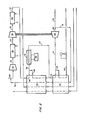
- atmospheric air is introduced into the system through inlet air filer 1 wherein dust and particulate matter are removed from the air prior to entering the initial air compressor 3 by way of line 2.
- the compressed air emanating from compressor 3 is conducted through conduit 4 to an aftercooler 5.
- the aftercooler 5 is operated by heat exchanging cooling water against the heated and compressed air stream.
- the air stream is conducted through conduit 6 to feed cooler 7.
- the feed air stream is cooled in this cooler 7 by heat exchange with air further processed in the system.
- the air stream is sufficiently reduced in temperature to condense water vapor contained within the air stream. Therefore, the air stream is passed through conduit 8 to aftercooler separator 9.
- the condensed moisture from the air is removed from the air stream as a bottom fraction 11.
- the separated air stream in a drier condition, is led off through conduit 10 to absorber precooler 12.
- This cooler is operated in heat exchange with a refrigeration unit 13.
- the air stream emanating from this cooler in conduit 14 is approximately 3.9°C.
- additional moisture in the air is condensed and removed in drier condensate separator 15. Again, condensed water is removed as a bottom fraction 17 from the separator, while dried air is removed as a head fraction from the upper portion of the separator.
- the air stream travels through conduit 16 to switching molecular sieve driers 18 and 19.
- the molecular sieve driers consist of two molecular sieve beds which remove water, carbon dioxide and hydrocarbons from the air stream. These impurities are absorbed by the molecular sieve material inside the vessel, thus resulting in a clean, dry air stream.
- the two drier units 18 and 19 are on a staggered cycle. One bed is absorbing the contained impurities from the air stream, while the other bed is being reactivated by flushing with warm gaseous nitrogen conducted from further down the air separation system.
- Each drier typically has an on-stream time of 2 to 12 hours after which it is taken off-stream for reactivation, and the other drier is put on-stream.
- the dryers are operated by valves 20, 21, 22 and 23.
- the air emanates from the molecular sieve driers through line 24 whereby it is introduced into drier filter 25, which insures that there is no carry-over of impurities or sieve components from the upstream apparatus.
- the cool, dry and clean air stream in line 26 is then recycled past feed cooler 7 to heat exchange with the incoming air stream in order to reduce the refrigeration load on refrigeration unit 13.
- the air stream is then conducted through line 27 and defrost heater 28 to be blended with recycled air in line 29 just upstream from air recycle compressor 30.
- the recycled air from line 52 and the feed air from line 29 are then compressed in air recycle compressor 30 and subsequently cooled in aftercooler 32 to which the air is admitted by way of line 31.
- the air stream in line 33 is further compressed in the compressor end 34 of a single compander.
- the compander consists of a compressor 34 which is mechanically joined and driven by an expander 48.
- the compressor and expander making up the compander are usually on the same shaft despite their functioning at different points of the stream flowpath.
- the compressed air stream is aftercooled in cooler 36 to which the air is admitted by way of line 35.
- the air stream at this point is at 33°C and 42.3 kg/cm 2.
- the air stream is introduced into main heat exchanger 44 through line 37. After an initial flow 38 through heat exchanger 44, the air stream, in line 39, is split into two separate lines 39 and 40. The air stream in line 39 becomes a split-out sidestream, while the air stream in line 40 is conducted back through heat exchanger 44 as a remaining stream.
- the air stream in line 39 is introduced into a Freon@ refrigeration unit 41 and 42. Upon introduction of the air stream into this unit, it is at 12.8°C. Upon exiting from the refrigeration unit, the air stream is at -77.8°C. At this point, the sidestream is reintroduced into the remaining stream in order to provide a significant level of refrigeration to the combined streams.
- the combined stream in line 45 then enters a second heat exchanger 54. A portion of the stream is then split-out as sidestream 47, which is at a temperature of -107°C and 42.4 kg/cm 2 .
- the sidestream is then expanded and further cooled in expander 48 of the single compander unit. The sidestream leaves the expander 48 in line 49 at -166°C and 7 kg/cm 2. At this point, the cooled and expanded stream is split into a distillation column air feed stream in line 50 and an air recycle stream in line 51.
- a remaining stream from line 45 passes through the second heat exchanger 54 in line 46.
- This cooled air stream is conducted to the distillation column 55 by means of line 53.
- the main and second heat exchangers 44 and 54 can be combined into one integral heat exchange unit.
- the streams are introduced into the high pressure column 56 at a point commensurate with their composition and phase.
- the distillation column is of a standard type wherein pure liquid nitrogen is removed from the high pressure column 56 as a head fraction at reboiler/condensor 58.
- the liquid nitrogen leaves the distillation column 55 through line 59 before being split into a product line and a reflux line.
- the reflux is reintroduced into the high pressure column 56, while the product liquid nitrogen is subcooled in heat exchanger 60, flashed to a lower temperature and conducted to a nitrogen separator through line 61.
- Liquid product nitrogen is removed from the bottom of the separator and is conducted to a liquid nitrogen storage unit via line 62 for further utilization.
- Impure reflux leaves the high pressure column 56 in line 69, is subcooled in heat exchanger 60 and introduced to the top of low pressure column 57.
- Crude liquid oxygen is removed as a bottom fraction in line 65 from the high pressure column 56. It is heat exchanged several times in exchangers 60 and 66 and is then introduced into low pressure column 57 for further refinement by way of line 67. A waste nitrogen stream 68 is removed from the head of the low pressure column for heat exchange and use as a reactivation gas in the upstream equipment. A pure oxygen product is removed from the bottom of the low pressure column 57 through line 63. After heat exchange with the crude oxygen flowing from the high pressure column to the low pressure column in exchanger 66, the liquid product oxygen is transported to a liquid oxygen storage unit via line 64.
- the compressed and aftercooled air stream in line 37 enters main heat exchanger 44 wherein a portion of the stream is split-out from the heat exchanger in a sidestream 39 to be further refrigerated by a multi-stage Freon@ refrigeration unit 41 and 42.
- This sidestream 43 is returned to the remaining stream 45 conducted through the heat exchanger 44.
- a second split-out sidestream 47 is removed from the remaining stream conducted through heat exchanger 54.
- This second split-out sidestream at a temperature of -107°C and a pressure of 42.4 kg/cm 2 is expanded through the expander 48 of a single compander to a temperature of -166°C at 7 kg/cm 2 .
- This stream 49 is further split into line 50 which leads to the distillation colum and line 51 which returns a portion of the cooled and expanded sidestream through the heat exchangers 44 and 54 countercurrently with the main remaining stream.
- This recycle stream 51 effectuates the refrigeration which occurs in the heat exchangers.
- the expanded and split air stream in line 50 can optionally be conducted through a third heat exchanger for further cooling before entering the distillation column. Such a heat exchanger is a tradeoff between increased separation efficiency and capital costs. It can be utilized depending upon the particular importance of initial cost or operational costs. Alternatively, this expanded stream may be recycled in full as discussed below.
- FIG. 3 The alternate embodiment noted above is shown in Fig. 3.
- This embodiment utilizes all of the upstream apparatus above the air recycle compressor 30 as shown in Fig. 1.
- air is compressed in air recycle compressor 130, and aftercooled in water cooled heat exchanger 132.
- the air is introduced into the compressor end 134 of a single compander and again is cooled in an aftercooler 136.
- the compressed air stream now at 41 kg/cm 2 is conducted along line 137 to main heat exchanger 144.
- the air stream is totally diverted from the heat exchanger 144 in line 139 to a single-stage Freon@ refrigeration unit 141.
- This is distinguished from the embodiment shown in Fig. 2 wherein the air stream is split into a remaining stream and a sidestream.
- All of the air stream in this alternate embodiment is conducted through the Freon@ refrigeration unit 141, wherein the air stream enters the exchanger at -34.4°C and exits the exchanger in line 143 at -40°C.
- the refrigerated air stream is then further cooled in main heat exchanger 144 before being divided into a split-out sidestream 147 and a remaining stream 145.
- the sidestream 147, at -84.4°C and 40 kg/cm 2 is expanded through the expander end 148 of a single compander to a temperature of -151°C and a pressure of 6.6 kg/cm 2. This expanded stream 149 is completely recycled back through the heat exchanger 144 countercurrent to the initial air stream 137.
- the expanded and recycled stream conducted through line 149 is introduced in line 152 to the feed air stream being conducted into the air recycle compressor 130 to complete its cyclic path.
- the remaining air stream in the heat exchanger 144 is conducted through line 145 to a second heat exchanger 154. This air stream is cooled to approximately -151 °C and is conducted in line 153 to the high pressure portion of the distillation column.
- the embodiments discussed above provide an economic manner in which to provide an air separation installation of a relatively smaller output, in a range of 27-90 tonnes per day, preferably 54 tonnes per day, rather than the greater than 90 tonnes per day installations of the prior art.
- Reduced capital outlay and installation size reduction are achieved without the use of cascade, double refrigeration provided by dual compander (compressor and expander) apparatus.
- the refrigeration necessary to operate the air separation unit and particularly the distillation column of this invention is achieved by the tandem operation of an in-line single compander unit and an in-line Freon@ refrigeration unit.
- the Freon@ refrigeration unit may provide a relatively large amount of refrigeration or a relatively minor amount of refrigeration.
Landscapes
- Engineering & Computer Science (AREA)
- Physics & Mathematics (AREA)
- Mechanical Engineering (AREA)
- Thermal Sciences (AREA)
- General Engineering & Computer Science (AREA)
- Separation By Low-Temperature Treatments (AREA)
- Transition And Organic Metals Composition Catalysts For Addition Polymerization (AREA)
- Gas Separation By Absorption (AREA)
Claims (9)
Priority Applications (1)
| Application Number | Priority Date | Filing Date | Title |
|---|---|---|---|
| AT82102989T ATE11820T1 (de) | 1981-04-20 | 1982-04-07 | Lufttrennung durch freon-kuehlung mit geringem energieverbrauch. |
Applications Claiming Priority (2)
| Application Number | Priority Date | Filing Date | Title |
|---|---|---|---|
| US06/255,910 US4375367A (en) | 1981-04-20 | 1981-04-20 | Lower power, freon refrigeration assisted air separation |
| US255910 | 1981-04-20 |
Publications (2)
| Publication Number | Publication Date |
|---|---|
| EP0063318A1 EP0063318A1 (de) | 1982-10-27 |
| EP0063318B1 true EP0063318B1 (de) | 1985-02-13 |
Family
ID=22970360
Family Applications (1)
| Application Number | Title | Priority Date | Filing Date |
|---|---|---|---|
| EP82102989A Expired EP0063318B1 (de) | 1981-04-20 | 1982-04-07 | Lufttrennung durch Freon-Kühlung mit geringem Energieverbrauch |
Country Status (9)
| Country | Link |
|---|---|
| US (1) | US4375367A (de) |
| EP (1) | EP0063318B1 (de) |
| JP (1) | JPS5939671B2 (de) |
| AT (1) | ATE11820T1 (de) |
| AU (1) | AU534408B2 (de) |
| BR (1) | BR8202249A (de) |
| CA (1) | CA1161745A (de) |
| DE (1) | DE3262281D1 (de) |
| MX (1) | MX159068A (de) |
Families Citing this family (34)
| Publication number | Priority date | Publication date | Assignee | Title |
|---|---|---|---|---|
| US4557735A (en) * | 1984-02-21 | 1985-12-10 | Union Carbide Corporation | Method for preparing air for separation by rectification |
| US4707994A (en) * | 1986-03-10 | 1987-11-24 | Air Products And Chemicals, Inc. | Gas separation process with single distillation column |
| US4715873A (en) * | 1986-04-24 | 1987-12-29 | Air Products And Chemicals, Inc. | Liquefied gases using an air recycle liquefier |
| US4705548A (en) * | 1986-04-25 | 1987-11-10 | Air Products And Chemicals, Inc. | Liquid products using an air and a nitrogen recycle liquefier |
| US4934148A (en) * | 1989-05-12 | 1990-06-19 | Union Carbide Corporation | Dry, high purity nitrogen production process and system |
| FR2661841B1 (fr) * | 1990-05-09 | 1992-07-17 | Air Liquide | Procede et appareil d'epuration par adsorption d'air destine a etre distille. |
| FR2681415B1 (fr) * | 1991-09-18 | 1999-01-29 | Air Liquide | Procede et installation de production d'oxygene gazeux sous haute pression par distillation d'air. |
| US5365741A (en) * | 1993-05-13 | 1994-11-22 | Praxair Technology, Inc. | Cryogenic rectification system with liquid oxygen boiler |
| US5376742A (en) * | 1993-09-23 | 1994-12-27 | Quantum Chemical Corporation | Monomer recovery in gas phase fluid bed olefin polymerization |
| FR2711778B1 (fr) * | 1993-10-26 | 1995-12-08 | Air Liquide | Procédé et installation de production d'oxygène et/ou d'azote sous pression. |
| FR2728663B1 (fr) | 1994-12-23 | 1997-01-24 | Air Liquide | Procede de separation d'un melange gazeux par distillation cryogenique |
| US5560763A (en) * | 1995-05-24 | 1996-10-01 | The Boc Group, Inc. | Integrated air separation process |
| GB9513766D0 (en) * | 1995-07-06 | 1995-09-06 | Boc Group Plc | Air separation |
| US5611218A (en) * | 1995-12-18 | 1997-03-18 | The Boc Group, Inc. | Nitrogen generation method and apparatus |
| US5678425A (en) * | 1996-06-07 | 1997-10-21 | Air Products And Chemicals, Inc. | Method and apparatus for producing liquid products from air in various proportions |
| US6000239A (en) * | 1998-07-10 | 1999-12-14 | Praxair Technology, Inc. | Cryogenic air separation system with high ratio turboexpansion |
| CN1079277C (zh) * | 1998-07-22 | 2002-02-20 | 北京燕山石油化工(集团)有限公司 | 净化风干燥器塔的自动切换系统及其控制程序 |
| KR20000033057A (ko) * | 1998-11-19 | 2000-06-15 | 서두칠 | 유리용융로의 청징부용 온도제어장치 |
| US6112550A (en) * | 1998-12-30 | 2000-09-05 | Praxair Technology, Inc. | Cryogenic rectification system and hybrid refrigeration generation |
| US6053008A (en) * | 1998-12-30 | 2000-04-25 | Praxair Technology, Inc. | Method for carrying out subambient temperature, especially cryogenic, separation using refrigeration from a multicomponent refrigerant fluid |
| US6298688B1 (en) | 1999-10-12 | 2001-10-09 | Air Products And Chemicals, Inc. | Process for nitrogen liquefaction |
| US6230519B1 (en) | 1999-11-03 | 2001-05-15 | Praxair Technology, Inc. | Cryogenic air separation process for producing gaseous nitrogen and gaseous oxygen |
| US6260380B1 (en) | 2000-03-23 | 2001-07-17 | Praxair Technology, Inc. | Cryogenic air separation process for producing liquid oxygen |
| FR2828273A1 (fr) * | 2001-07-31 | 2003-02-07 | Air Liquide | Procede d'alimentation en air epure d'une unite de distillation d'air cryogenique et installation de mise en oeuvre de ce procede |
| FR2830928B1 (fr) * | 2001-10-17 | 2004-03-05 | Air Liquide | Procede de separation d'air par distillation cryogenique et une installation pour la mise en oeuvre de ce procede |
| US7296437B2 (en) * | 2002-10-08 | 2007-11-20 | L'air Liquide, Societe Anonyme A Directoire Et Conseil De Surveillance Pour L'etude Et L'exploitation Des Procedes Georges Claude | Process for separating air by cryogenic distillation and installation for implementing this process |
| US6591632B1 (en) | 2002-11-19 | 2003-07-15 | Praxair Technology, Inc. | Cryogenic liquefier/chiller |
| US7712543B2 (en) * | 2004-06-24 | 2010-05-11 | Tyco Fire Products Lp | Residential dry sprinkler design method and system |
| US20070084225A1 (en) * | 2005-10-13 | 2007-04-19 | Imperial Research Llc | Air cycle system with variable mix recuperator |
| US8020408B2 (en) | 2006-12-06 | 2011-09-20 | Praxair Technology, Inc. | Separation method and apparatus |
| JP5643491B2 (ja) * | 2009-07-24 | 2014-12-17 | 大陽日酸株式会社 | 空気液化分離方法及び装置 |
| US9726427B1 (en) | 2010-05-19 | 2017-08-08 | Cosmodyne, LLC | Liquid nitrogen production |
| CN112857809B (zh) * | 2020-12-31 | 2022-08-19 | 中国航发沈阳发动机研究所 | 一种低温换热装置 |
| US12117240B2 (en) | 2021-07-19 | 2024-10-15 | L'air Liquide, Societe Anonyme Pour L'etude Et L'exploitation Des Procedes Georges Claude | Integrated multicomponent refrigerant and air separation process for producing liquid oxygen |
Citations (2)
| Publication number | Priority date | Publication date | Assignee | Title |
|---|---|---|---|---|
| US3905201A (en) | 1969-08-12 | 1975-09-16 | Union Carbide Corp | Air separation with work expansion to high and low pressure rectification stages |
| US4152130A (en) | 1977-03-19 | 1979-05-01 | Air Products And Chemicals, Inc. | Production of liquid oxygen and/or liquid nitrogen |
Family Cites Families (6)
| Publication number | Priority date | Publication date | Assignee | Title |
|---|---|---|---|---|
| US3091094A (en) * | 1957-07-04 | 1963-05-28 | Linde Eismasch Ag | Process of and apparatus for separating gases with cold production by workproducing expansion of low-boiling product |
| US3079759A (en) * | 1961-03-22 | 1963-03-05 | Air Prod & Chem | Separation of gaseous mixtures |
| GB943669A (en) * | 1961-11-03 | 1963-12-04 | Petrocarbon Dev Ltd | Separation of oxygen from air |
| DE1275076B (de) * | 1965-07-20 | 1968-08-14 | Linde Ag | Verfahren zur Durchfuehrung des Waermeaustausches bei der Tieftemperaturzerlegung von Gasgemischen |
| NL7210626A (de) * | 1972-08-03 | 1974-02-05 | ||
| IT1019710B (it) * | 1974-07-12 | 1977-11-30 | Nuovo Pignone Spa | Processo ed apparato per la produ zione di elevate percentuali di os sigeno e/o azoto allo stato liquido |
-
1981
- 1981-04-20 US US06/255,910 patent/US4375367A/en not_active Expired - Fee Related
-
1982
- 1982-03-31 CA CA000400315A patent/CA1161745A/en not_active Expired
- 1982-04-02 AU AU82285/82A patent/AU534408B2/en not_active Ceased
- 1982-04-07 AT AT82102989T patent/ATE11820T1/de not_active IP Right Cessation
- 1982-04-07 DE DE8282102989T patent/DE3262281D1/de not_active Expired
- 1982-04-07 EP EP82102989A patent/EP0063318B1/de not_active Expired
- 1982-04-19 MX MX192310A patent/MX159068A/es unknown
- 1982-04-19 BR BR8202249A patent/BR8202249A/pt unknown
- 1982-04-20 JP JP57066070A patent/JPS5939671B2/ja not_active Expired
Patent Citations (2)
| Publication number | Priority date | Publication date | Assignee | Title |
|---|---|---|---|---|
| US3905201A (en) | 1969-08-12 | 1975-09-16 | Union Carbide Corp | Air separation with work expansion to high and low pressure rectification stages |
| US4152130A (en) | 1977-03-19 | 1979-05-01 | Air Products And Chemicals, Inc. | Production of liquid oxygen and/or liquid nitrogen |
Non-Patent Citations (1)
| Title |
|---|
| R.E. LATIMER: "Distillation of Air. The primary distillation is carried out in a single, double, or triple distilling column and in a crude argon column to recover oxygen, nitrogen, and argon; recovery is made by distillation of the rare gases krypton, xenon, neon, and helium", CHEMICAL ENGINEERING PROGRESS, vol. 62, no. 2, 1 February 1967 (1967-02-01), pages 35 - 59, XP001253423 |
Also Published As
| Publication number | Publication date |
|---|---|
| BR8202249A (pt) | 1983-04-05 |
| US4375367A (en) | 1983-03-01 |
| AU8228582A (en) | 1983-01-13 |
| AU534408B2 (en) | 1984-01-26 |
| DE3262281D1 (en) | 1985-03-28 |
| EP0063318A1 (de) | 1982-10-27 |
| CA1161745A (en) | 1984-02-07 |
| MX159068A (es) | 1989-04-14 |
| JPS5939671B2 (ja) | 1984-09-25 |
| JPS57182069A (en) | 1982-11-09 |
| ATE11820T1 (de) | 1985-02-15 |
Similar Documents
| Publication | Publication Date | Title |
|---|---|---|
| EP0063318B1 (de) | Lufttrennung durch Freon-Kühlung mit geringem Energieverbrauch | |
| CA1078301A (en) | Production of liquid oxygen and/or liquid nitrogen | |
| AU653120B2 (en) | Process for low-temperature air fractionation | |
| US3216206A (en) | Low temperature distillation of normally gaseous substances | |
| US4595405A (en) | Process for the generation of gaseous and/or liquid nitrogen | |
| CN112005067B (zh) | 用于从产氮低温空气分离单元增强回收氩和氧的系统和方法 | |
| US4464188A (en) | Process and apparatus for the separation of air | |
| US4617036A (en) | Tonnage nitrogen air separation with side reboiler condenser | |
| US4592766A (en) | Parallel stream heat exchange for separation of ethane and higher hydrocarbons from a natural or refinery gas | |
| US4806136A (en) | Air separation method with integrated gas turbine | |
| KR102438959B1 (ko) | 질소 생성 극저온 공기 분리 유닛으로부터의 아르곤 및 산소의 향상된 회수율을 위한 시스템 및 방법 | |
| KR0149174B1 (ko) | 공기로부터의 질소의 제조 방법 및 장치 | |
| US2873583A (en) | Dual pressure cycle for air separation | |
| US4367082A (en) | Air separating system | |
| US4704146A (en) | Liquid carbon dioxide recovery from gas mixtures with methane | |
| CN111989528B (zh) | 用于从产氮低温空气分离单元增强回收氩和氧的系统和方法 | |
| US5325674A (en) | Process for the production of nitrogen by cryogenic distillation of atmospheric air | |
| KR20200130478A (ko) | 중압 극저온 공기 분리 유닛으로부터의 질소 및 아르곤의 고 회수율을 위한 시스템 및 방법 | |
| CN105466154B (zh) | 一种空分工艺方法 | |
| CN101270952A (zh) | 一种空气回热式的矿井瓦斯气的分离液化方法及设备 | |
| US4659351A (en) | Combined process to produce liquid helium, liquid nitrogen, and gaseous nitrogen from a crude helium feed | |
| US4783208A (en) | Air separation | |
| US4732597A (en) | Low energy consumption method for separating gaseous mixtures and in particular for medium purity oxygen production | |
| US2526996A (en) | Method and apparatus for separating mixed gases | |
| CN106595221A (zh) | 制氧系统和制氧方法 |
Legal Events
| Date | Code | Title | Description |
|---|---|---|---|
| PUAI | Public reference made under article 153(3) epc to a published international application that has entered the european phase |
Free format text: ORIGINAL CODE: 0009012 |
|
| AK | Designated contracting states |
Designated state(s): AT BE CH DE FR GB IT LU NL SE |
|
| 17P | Request for examination filed |
Effective date: 19830210 |
|
| ITF | It: translation for a ep patent filed | ||
| GRAA | (expected) grant |
Free format text: ORIGINAL CODE: 0009210 |
|
| AK | Designated contracting states |
Designated state(s): AT BE CH DE FR GB IT LI LU NL SE |
|
| PG25 | Lapsed in a contracting state [announced via postgrant information from national office to epo] |
Ref country code: LI Free format text: LAPSE BECAUSE OF NON-PAYMENT OF DUE FEES Effective date: 19850213 Ref country code: CH Free format text: LAPSE BECAUSE OF NON-PAYMENT OF DUE FEES Effective date: 19850213 |
|
| REF | Corresponds to: |
Ref document number: 11820 Country of ref document: AT Date of ref document: 19850215 Kind code of ref document: T |
|
| REF | Corresponds to: |
Ref document number: 3262281 Country of ref document: DE Date of ref document: 19850328 |
|
| PG25 | Lapsed in a contracting state [announced via postgrant information from national office to epo] |
Ref country code: LU Free format text: LAPSE BECAUSE OF NON-PAYMENT OF DUE FEES Effective date: 19850430 |
|
| ET | Fr: translation filed | ||
| PLBI | Opposition filed |
Free format text: ORIGINAL CODE: 0009260 |
|
| 26 | Opposition filed |
Opponent name: LINDE AKTIENGESELLSCHAFT, WIESBADEN Effective date: 19851022 |
|
| NLR1 | Nl: opposition has been filed with the epo |
Opponent name: LINDE AKTIENGESELLSCHAFT |
|
| PGFP | Annual fee paid to national office [announced via postgrant information from national office to epo] |
Ref country code: AT Payment date: 19860305 Year of fee payment: 5 |
|
| PGFP | Annual fee paid to national office [announced via postgrant information from national office to epo] |
Ref country code: NL Payment date: 19870430 Year of fee payment: 6 |
|
| PG25 | Lapsed in a contracting state [announced via postgrant information from national office to epo] |
Ref country code: GB Effective date: 19890407 Ref country code: AT Effective date: 19890407 |
|
| PG25 | Lapsed in a contracting state [announced via postgrant information from national office to epo] |
Ref country code: SE Effective date: 19890408 |
|
| PG25 | Lapsed in a contracting state [announced via postgrant information from national office to epo] |
Ref country code: BE Effective date: 19890430 |
|
| BERE | Be: lapsed |
Owner name: AIR PRODUCTS AND CHEMICALS INC. Effective date: 19890430 |
|
| PG25 | Lapsed in a contracting state [announced via postgrant information from national office to epo] |
Ref country code: NL Effective date: 19891101 |
|
| GBPC | Gb: european patent ceased through non-payment of renewal fee | ||
| NLV4 | Nl: lapsed or anulled due to non-payment of the annual fee | ||
| PG25 | Lapsed in a contracting state [announced via postgrant information from national office to epo] |
Ref country code: FR Free format text: LAPSE BECAUSE OF NON-PAYMENT OF DUE FEES Effective date: 19891228 |
|
| REG | Reference to a national code |
Ref country code: CH Ref legal event code: PL |
|
| PG25 | Lapsed in a contracting state [announced via postgrant information from national office to epo] |
Ref country code: DE Effective date: 19900103 |
|
| REG | Reference to a national code |
Ref country code: FR Ref legal event code: ST |
|
| RDAG | Patent revoked |
Free format text: ORIGINAL CODE: 0009271 |
|
| STAA | Information on the status of an ep patent application or granted ep patent |
Free format text: STATUS: PATENT REVOKED |
|
| 27W | Patent revoked |
Effective date: 19900705 |
|
| GBPR | Gb: patent revoked under art. 102 of the ep convention designating the uk as contracting state | ||
| EUG | Se: european patent has lapsed |
Ref document number: 82102989.9 Effective date: 19891114 |
|
| APAH | Appeal reference modified |
Free format text: ORIGINAL CODE: EPIDOSCREFNO |