EP0063074A1 - High speed rotor especially for flywheel - Google Patents
High speed rotor especially for flywheel Download PDFInfo
- Publication number
- EP0063074A1 EP0063074A1 EP82400574A EP82400574A EP0063074A1 EP 0063074 A1 EP0063074 A1 EP 0063074A1 EP 82400574 A EP82400574 A EP 82400574A EP 82400574 A EP82400574 A EP 82400574A EP 0063074 A1 EP0063074 A1 EP 0063074A1
- Authority
- EP
- European Patent Office
- Prior art keywords
- rim
- arms
- hub
- arm
- loop
- Prior art date
- Legal status (The legal status is an assumption and is not a legal conclusion. Google has not performed a legal analysis and makes no representation as to the accuracy of the status listed.)
- Granted
Links
Images


Classifications
-
- F—MECHANICAL ENGINEERING; LIGHTING; HEATING; WEAPONS; BLASTING
- F16—ENGINEERING ELEMENTS AND UNITS; GENERAL MEASURES FOR PRODUCING AND MAINTAINING EFFECTIVE FUNCTIONING OF MACHINES OR INSTALLATIONS; THERMAL INSULATION IN GENERAL
- F16F—SPRINGS; SHOCK-ABSORBERS; MEANS FOR DAMPING VIBRATION
- F16F15/00—Suppression of vibrations in systems; Means or arrangements for avoiding or reducing out-of-balance forces, e.g. due to motion
- F16F15/30—Flywheels
- F16F15/305—Flywheels made of plastics, e.g. fibre-reinforced plastics [FRP], i.e. characterised by their special construction from such materials
-
- Y—GENERAL TAGGING OF NEW TECHNOLOGICAL DEVELOPMENTS; GENERAL TAGGING OF CROSS-SECTIONAL TECHNOLOGIES SPANNING OVER SEVERAL SECTIONS OF THE IPC; TECHNICAL SUBJECTS COVERED BY FORMER USPC CROSS-REFERENCE ART COLLECTIONS [XRACs] AND DIGESTS
- Y10—TECHNICAL SUBJECTS COVERED BY FORMER USPC
- Y10T—TECHNICAL SUBJECTS COVERED BY FORMER US CLASSIFICATION
- Y10T74/00—Machine element or mechanism
- Y10T74/21—Elements
- Y10T74/2117—Power generating-type flywheel
Definitions
- the elongation in the bar is the third of the elongation in the rim and that consequently one cannot center the rim j by the bar b without obligatorily introducing connections at points A and B, which connections will themselves introduce constraints to ensure the coincidence of the bar-rim contact points.
- the Applicant has developed a technique which has evolved over the course of its studies, in an attempt to definitively resolve the basic structure problem of rotors with high rotational speed, more particularly those intended to be used as as flywheel for energy storage-recovery applications.
- the Applicant firstly revealed for the first time the subcircular rotors in its French patent N ° 70 08 394 of March 9, 1970. It will be recalled briefly that the subcircular concept is based on the following principle: the elongation of the rim j (see FIG. 2) corresponds to a change in shape and not to an increase in diameter, between the initial pseudopolygonal shape at rest P and the outer circle C whose radius is that of the support webs b of the rim. It is thus possible to use for the rim a material which has a greater elongation than that accepted by the arms, either because of their modulus, or because of their shape.
- the stress that the rim applies on the arms can be measured. This depends, among other parameters, on the shape of the rim, once placed on the arm. This results in a certain residual subcircularity at the maximum speed on which the level of compression on the arm depends, as, moreover, appears on reading the diagram in FIG. 2. This compression of the rim on the arms promotes their joining already effected. , for example, by means of a collage.
- FIG. 3 The principle of this solution has been shown diagrammatically in FIG. 3 in which we find the combination of a rim i, a hub m o of at least one connecting arm b with two branches b l , b 2 surrounding said hub .
- Masses ma l and ma 2 are located at the ends of the arm b so that, during rotation, they secure, by pressure, between the arm and the rim, on the one hand, and by traction on the branches between the arm and the hub, on the other hand.
- Anisotropic masses ma n distributed between the arms keep the circularity of the rim constant. Static and dynamic balancing is ensured by the action of electromechanical means e and t acting differently on the masses located ma l , ma 2 , from sensors c a .
- the rotor can be balanced by acting differently by the action of an electromechanical system e, t, from information from sensors c.
- the present invention relates to a process for producing a high-speed rotor more particularly applicable to a flywheel, which constitutes an improved synthesis of the prior systems of the Applicant which have been discussed above.
- This process not only makes it possible to eliminate the drawbacks inherent in each of the prior systems, taken in themselves, but also brings significant advantages which will become apparent as the detailed description of the invention which will be given later.
- the invention also relates to high speed rotors more particularly applicable to flywheels which implement the method according to the invention.
- the method according to the invention essentially consists in centering a rim relative to a hub by means of a certain number of link arms, each of which takes the form of an elongated loop, the two sides of which include rectilinear parts, the internal end of said loop being centered and held against the centrifugal force by a central element forming part of the hub, while the external end of said loop comes to bear constantly against the rim on which it is preferably assembled by gluing, a mass being included inside said outer end of the loop to cause the desired elongation of the loop under the effect of centrifugal force and ensure constant contact between the arm and the rim.
- the link arms are produced by winding, on a suitable mandrel, filamentary composite materials such as glass fibers, carbon, polymers, boron, steel or the like.
- the end mass of the arms is dimensioned such that the end of the arm on the rim side is always in abutment on the rim, which leads to a certain subcircularity of the rim, during rotation, and therefore reinforces the arm-rim connection while maintaining the advantage of having arms remaining in tension.
- connection between the rim and the hub is carried out by means of arms or spokes formed in the manner described below from the main but not exclusive use of materials. filamentary composites.
- each arm is made up, as shown in FIGS. 5, 6 and 7, by winding, on a suitable mandrel, of filamentary composite materials such as fiberglass, carbon, polymers, boron, steel , etc. which gives said arm the general shape of an elongated loop whose two sides have rectilinear parts.
- the arm consists of two thin plates 1a and 1b joined at their ends by rounded elements 2a and 2b, it should be noted that these rounded elements can be circular but can advantageously also have an optimized elongated shape, called Horn shape, in order to improve the distribution of mechanical stresses in the connection zone between the arm and the part with which it is in contact.
- the circular crown 5 comprises, at the places where the different arms are to be applied, bearing surfaces 5a which are machined exactly to the internal support form of the end 2b of the arm.
- each arm receives, at the end 2a located on the side of the rim 6, on the one hand an internal part 7 whose mass is defined so as to cause an elongation of the arm adapted to that of the rim 6, on the other hand, a second external part 8 which has the effect of ensuring the adaptation of the shapes allowing a bonding by bonding with the rim 6.
- each of the arms can advantageously be equipped with stiffeners, such as that shown in 9, which have the effect of increasing the stiffness of the attachment of the rim relative to the hub, either in torque if the embodiment of Figure 5 is implemented, or in the axial direction if the embodiment of Figure 6 is applied.
- the central fixing ring consists of an appropriate number of thin elementary rings 9a, 9b ... 9n assembled between them by gluing. Furthermore, each of the elementary rings consists of two thin half-sectors 9a 1 , 9a 2 for the elementary crown 9a and 9b 1 , 9b 2 for the elementary crown 9b.
- the half-sectors constituting an elementary crown are assembled by bonding, it should be noted that the bonding lines 9a 3 of the elementary crown 9a and the bonding lines 9b 3 of the elementary crown 9b are offset by 90 ° with respect to the others when the elementary rings 9a and 9b are assembled together by gluing and so on until the assembly of the elementary crown 9n.
- the number of arms can be adapted to each final configuration of the high speed rotor. Thus, if the rim has a certain height, we will have to use at least two sets of arms, one at each end of the rim, or even a greater number of sets of arms depending on the height of said rim. .
- the height of the rim 6 requires, in this case, the use of two sets of arms 10a and 10b mounted at the two ends of said rim.
- Each set here consists of eight arms paired by pairs of opposite arms: lla, llb, 12a, 12b, 13a, 13b and 14a, 14b.
- Each of the arms here is of the type of FIG. 5 and the central crown here consists of two flanges 4a and 4b joined together by adapter pieces 3, 3a, 3b on which the internal ends 2b of the arms bear.
- the internal flange 4a is part of the hub 16.
- the central shaft 18 is here rotating and integral with said hub 16. Bearings 19 allow the assembly to be mounted in a frame as will be seen in detail.
- central circular fixing ring 5 is continuous.
- This crown which is part of the hub is fixed by fasteners 15 between the shoulder 16a of the middle part of the hub 16 and an outer crown 17.
- the central shaft 18 is again here integral with the hub 16 and bearings 19 allow mounting the whole in a frame.
- Arms of the type of that of FIG. 8 could also be used. This is how one can enhance the characteristic of the invention according to which filamentary composite materials are used for the constitution of the arms. In this eventuality, it is advantageously possible to apply the variant embodiment shown in FIG. 14 in which the end of the arm, on the rim side, is glued directly against the rim and in which materials are advantageously used, the longitudinal elastic modules E and the masses specific e lead to different values of the ratio E for the arms on the one hand and the rim on the other.
- the arm is for example of the type of that shown in FIG. 5 in which the adaptation part 8 is here replaced by a part 20 which includes the end 2a of the arm containing the internal mass 7, this part 20 being provided at its end in contact with the rim 6 with a plate 21 made of a material whose elongation characteristics are such that it can remain on one side secured to the part 20 without tangential elongation at this contact and on the other side remain secured to the rim by accepting its tangential elongation, this regardless of this elongation, throughout the speed range.
- This plate 21 can be made of a resin or an elastomer advantageously reinforced with fiberglass, carbon, polymer, etc.
- the plate 21 is thus glued on one side to the part 20 and on the other on the rim 6.
- the part 20 can be provided at its end with a stack of thin sheets of a material capable of great elongation, such as "Mylar” "Kapton” or similar self-adhesive on its two faces or with gluing of the sheets together and on the rim and the part 20.
- suspension with rotating central shaft 18t in FIGS. 16 and 17 there are two types of suspension, namely: the suspension with rotating central shaft 18t in FIGS. 16 and 17 and the suspension with fixed central shaft 18f in FIG. 18.
- the central shaft 18t which is integral with the hub of the rotor R is mounted on either side of said rotor in the movable elements of two bearings 19 whose fixed elements are integral with two constituent cylinders 22 of the frame.
- the upper one serves as a casing for the electric motor-generator of any known type whose fixed electromagnetic elements 23 are integral with the cylinder 22 and the movable electromagnetic elements 24 integral with the central rotating shaft 18t.
- the motor makes it possible to drive the rotor forming a flywheel at high speed to store energy in kinetic form.
- This kinetic energy is returned in electrical form by the generator or even in mechanical form by the rotating shaft driven by the rotor on its kinetic energy.
- the rotating central shaft 18t on which the rotor R forming the flywheel is fixed is supported in overhang by two bearings 19 mounted at the two ends of a cylinder 22 mounted on the upper part of the frame
- an electric motor generator 23-24 is mounted in said cylinder 22 and the assembly operates in the same manner as the embodiment of FIG. 16 described above.
- the suspension here has a fixed central shaft 18f.
- the shaft 18f is fixed at its two ends in the axis of the frame B, while the rotor R is secured to a central cylinder 22 itself secured to the movable elements of the bearings 19 whose elements fixed are integral with the fixed central shaft 18f.
- the fixed electromagnetic elements 23 of the motor-generator are integral with the fixed central shaft 18t while the mobile electromagnetic elements 24 of this motor are integral with the rotor R.
- FIG. 18 operates in a manner completely similar to that described above.
Abstract
Description
On connaît les nombreuses applications des rotors à haute vitesse de rotation. Une des applications possibles est celle des volants d'inertie capables de stocker de l'énergie sous forme cinétique et de la restituer sous forme mécanique.The many applications of rotors with high rotational speed are known. One of the possible applications is that of flywheels capable of storing energy in kinetic form and of restoring it in mechanical form.
Avant d'aller plus avant dans la description de la présente invention, on rappellera tout d'abord, très succinctement, en se référant à la figure 1 l'un des problèmes de base théorique que pose la structure des rotors.Before going further in the description of the present invention, it will be recalled first of all, very succinctly, with reference to FIG. 1, one of the basic theoretical problems posed by the structure of the rotors.
On considèrera à cet effet une jante mince i de rayon R centrée en O et une barre de liaison b de longueur 2R centrée également sur O et sur laquelle la jante j repose à l'arrêt. Si l'on suppose que la jante j et la barre b sont constituées de matériaux présentant la même masse spécifique et le même module d'élasticité E, et si l'on examine les allongements de la jante j et de la barre b pour des vitesses de rotation égales impliquant la même vitesse périphérique V pour la jante et pour les extrémités A et B de la barre de liaison, on voit que :
- a) la contrainte dans la jante j est σ1 = ρV2 et que l'allongement correspondant est :

- b) la contrainte dans la barre b, qui est nulle aux points A et B, croît jusqu'à un maximum au centre 0 dont la valeur est σ- 2 = ½ρV2 et que l'allongement correspondant sur la lonqueur d'un rayon est :

- a) the stress in the rim j is σ 1 = ρV 2 and that the corresponding elongation is:
- b) the stress in the bar b, which is zero at points A and B, increases to a maximum at the center 0 whose value is σ- 2 = ½ρV 2 and that the corresponding elongation on the lengthwise of a radius East :
En comparant les relations ci-dessus concernant les allongements, on constate que l'allongement dans la barre est le tiers de l'allongement dans la jante et que par conséquent on ne peut pas centrer la jante j par la barre b sans obligatoirement introduire des liaisons aux points A et B, lesquelles liaisons vont elles-mêmes introduire des contraintes pour assurer la coïncidence des points de contact barre-jante.By comparing the relations above concerning the elongations, it is noted that the elongation in the bar is the third of the elongation in the rim and that consequently one cannot center the rim j by the bar b without obligatorily introducing connections at points A and B, which connections will themselves introduce constraints to ensure the coincidence of the bar-rim contact points.
La Demanderesse a mis au point une technique qui a évolué au fur et à mesure de ses études, pour tenter de résoudre de façon définitive le problème de structure de base des rotors à haute vitesse de rotation, plus particulièrement ceux destinés à être utilisés en tant que volant d'inertie pour des applications de stockage-récupération d'énergie.The Applicant has developed a technique which has evolved over the course of its studies, in an attempt to definitively resolve the basic structure problem of rotors with high rotational speed, more particularly those intended to be used as as flywheel for energy storage-recovery applications.
La Demanderesse a tout d'abord révélé pour la première fois les rotors subcirculaires dans son brevet français N° 70 08 394 du 9 Mars 1970. On rappellera brièvement que le concept subcirculaire est basé sur le principe suivant : l'allongement de la jante j (voir figure 2) correspond à un changement de forme et non à une augmentation de diamètre, entre la forme pseudopolygonale initiale au repos P et le cercle extérieur C dont le rayon est celui des voiles de support b de la jante. Il est ainsi possible d'utiliser pour la jante un matériau qui présente un allongement relatif plus grand que celui accepté par les bras, soit du fait de leur module, soit du fait de leur forme. De plus, en agissant sur la forme de la jante lors de sa mise en place sur les bras, on peut doser la contrainte que la jante applique sur les bras. Celle-ci dépend, entre autres paramètres, de la forme de la jante, une fois mise en place sur le bras. Il en résulte une certaine subcircularité résiduelle à la vitesse maximale dont dépend le niveau de compression sur le bras, comme cela apparaît d'ailleurs à la lecture du schéma de la figure 2. Cette compression de la jante sur les bras favorise leur solidarisation déjà effectuée, par exemple, au moyen d'un collage.The Applicant firstly revealed for the first time the subcircular rotors in its French patent N ° 70 08 394 of March 9, 1970. It will be recalled briefly that the subcircular concept is based on the following principle: the elongation of the rim j (see FIG. 2) corresponds to a change in shape and not to an increase in diameter, between the initial pseudopolygonal shape at rest P and the outer circle C whose radius is that of the support webs b of the rim. It is thus possible to use for the rim a material which has a greater elongation than that accepted by the arms, either because of their modulus, or because of their shape. In addition, by acting on the shape of the rim when it is placed on the arms, the stress that the rim applies on the arms can be measured. This depends, among other parameters, on the shape of the rim, once placed on the arm. This results in a certain residual subcircularity at the maximum speed on which the level of compression on the arm depends, as, moreover, appears on reading the diagram in FIG. 2. This compression of the rim on the arms promotes their joining already effected. , for example, by means of a collage.
Il y a lieu de noter que cette solution, appliquée aux jantes de petit diamètre, reste valable pour des épaisseurs relativement faibles, de l'ordre de 10 % du rayon. Par contre, pour des jantes plus épaisses et pour des rotors de plus grand diamètre on est amené à dissocier la jante en plusieurs couches, avec ou sans cales intermédiaires. Cette technique rend difficile le maintien d'un bon équilibrage du rotor dans toute la plage de vitesses, compte tenu de l'accumulation des tolérances mécaniques d'assemblage constituant les jantes en matériau composite. De plus, la complexité d'assemblage accroît considérablement le coût de conception et de fabrication.It should be noted that this solution, applied to small diameter rims, remains valid for relatively small thicknesses, of the order of 10% of the radius. On the other hand, for thicker rims and for rotors of larger diameter, it is necessary to dissociate the rim into several layers, with or without intermediate shims. This technique makes it difficult to maintain good balance of the rotor throughout the speed range, given the accumulation of mechanical assembly tolerances constituting the rims of composite material. Of moreover, the complexity of assembly considerably increases the cost of design and manufacture.
La Demanderesse a présenté dans son brevet français N° 78 24 955 du 29 Août 1978 une solution différente mettant en oeuvre les effets d'inertie d'une masse additionnelle permettant l'allongement des bras de telle sorte que cet allongement soit compatible avec celui d'une jante initialement circulaire.The Applicant has presented in its French patent N ° 78 24 955 of August 29, 1978 a different solution implementing the inertia effects of an additional mass allowing the elongation of the arms so that this elongation is compatible with that of 'an initially circular rim.
Le principe de cette solution a été schématisé sur la figure 3 sur laquelle on retrouve la combinaison d'une jante i, d'un moyeu mo d'au moins un bras de liaison b à deux branches bl, b2 entourant ledit moyeu. Des masses mal et ma2 sont localisées aux extrémités du bras b de façon que, en cours de rotation, elles assurent la solidarisation, par pression, entre le bras et la jante, d'une part, et par traction sur les branches entre le bras et le moyeu, d'autre part. Des masses anisotropes man réparties entre les bras conservent constante la circularité de la jante. L'équilibrage statique et dynamique est assuré par action de moyens électromécaniques e et t agissant différentiellement sur les masses localisées mal, ma2, à partir de capteurs ca.The principle of this solution has been shown diagrammatically in FIG. 3 in which we find the combination of a rim i, a hub m o of at least one connecting arm b with two branches b l , b 2 surrounding said hub . Masses ma l and ma 2 are located at the ends of the arm b so that, during rotation, they secure, by pressure, between the arm and the rim, on the one hand, and by traction on the branches between the arm and the hub, on the other hand. Anisotropic masses ma n distributed between the arms keep the circularity of the rim constant. Static and dynamic balancing is ensured by the action of electromechanical means e and t acting differently on the masses located ma l , ma 2 , from sensors c a .
Cette solution présente plusieurs difficultés d'application, parmi lesquelles on peut citer :
- - le niveau de précision et de stabilité du centrage des bras est difficilement compatible avec la nécessité d'un bon équilibrage par collage ;
- - il n'est pas possible de compenser une dissymétrie des deux demi-bras due à une dispersion des caractéristiques des matériaux ;
- - la liaison entre les bras et le moyeu central par collage et la forme même des bras se prêtent mal au passage de couples relativement importants en raison de l'effet de décollement dit "peeling".
- - the level of precision and stability of the centering of the arms is hardly compatible with the need for good balancing by gluing;
- - it is not possible to compensate for an asymmetry of the two half-arms due to a dispersion of the characteristics of the materials;
- - The connection between the arms and the central hub by gluing and the very shape of the arms do not lend themselves to the passage of relatively large torques due to the so-called "peeling" separation effect.
La Demanderesse a présenté dans son brevet français N° 79.13 688 du 29 Mai 1979 une solution différente de la réalisation d'un rotor de type subcirculaire à moyeu- voile-jante. On rappellera brièvement en se référant à la figure 4 que cette solution consiste à réduire les contraintes radiales dans les voiles b en dissociant le système moyeu m -voiles b recevant en appui la paroi de la jante subcirculaire j, puis en localisant la masse principale m desdits voiles vers la jante, de telle sorte que la force centrifuge f qui en résulte vienne en déduction de la force de compression radiale F dirigée vers l'axe de rotation, ce qui permet de diminuer les forces de compression s'exerçant sur chaque voile.The Applicant has presented in its French patent No. 79.13 688 of May 29, 1979 a different solution to the production of a rotor of the subcircular type with hub-sail-rim. It will be recalled briefly with reference to FIG. 4 that this solution consists in reducing the radial stresses in the sails b by dissociating the hub system m - sails b receiving in support the wall of the subcircular rim j, then locating the main mass m of said sails towards the rim, so that the resulting centrifugal force f comes as a deduction from the radial compression force F directed towards the axis of rotation, which makes it possible to reduce the compression forces exerted on each sail.
Là encore, le rotor peut être équilibré en agissant différentiellement par l'action d'un système électromécanique e, t, à partir d'informations de capteurs c .Again, the rotor can be balanced by acting differently by the action of an electromechanical system e, t, from information from sensors c.
Cette solution présente elle aussi les difficultés d'application inhérentes aux jantes de type subcirculaire mentionnées précédemment.This solution also presents the application difficulties inherent in the rims of the subcircular type mentioned above.
La présente invention concerne un procédé de réalisation d'un rotor à haute vitesse plus particulièrement applicable à un volant d'inertie, qui constitue une synthèse améliorée des systèmes antérieurs de la Demanderesse dont il a été question ci-dessus. Ce procédé permet non seulement d'éliminer les inconvénients inhérents à chacun des systèmes antérieurs, pris en soi, mais encore apporte des avantages importants qui ressortiront au fur et à mesure de la description détaillée de l'invention qui va être faite plus loin.The present invention relates to a process for producing a high-speed rotor more particularly applicable to a flywheel, which constitutes an improved synthesis of the prior systems of the Applicant which have been discussed above. This process not only makes it possible to eliminate the drawbacks inherent in each of the prior systems, taken in themselves, but also brings significant advantages which will become apparent as the detailed description of the invention which will be given later.
L'invention concerne également les rotors à haute vitesse plus particulièrement applicables à des volants d'inertie qui mettent en oeuvre le procédé selon l'invention. Le procédé conforme à l'invention consiste essentiellement à réaliser le centrage d'une jante par rapport à un moyeu par l'intermédiaire d'un certain nombre de bras de liaison dont chacun affecte la forme d'une boucle allongée dont les deux côtés comportent des parties rectilignes, l'extrémité interne de ladite boucle étant centrée et maintenue contre la force centrifuge par un élément central faisant partie du moyeu, tandis que l'extrémité externe de ladite boucle vient porter constamment contre la jante sur laquelle elle est assemblée de préférence par collage, une masse étant incluse à l'intérieur de ladite extrémité externe de la boucle pour provoquer l'allongement désiré de la boucle sous l'effet de la force centrifuge et assurer un contact constant entre bras et jante.The invention also relates to high speed rotors more particularly applicable to flywheels which implement the method according to the invention. The method according to the invention essentially consists in centering a rim relative to a hub by means of a certain number of link arms, each of which takes the form of an elongated loop, the two sides of which include rectilinear parts, the internal end of said loop being centered and held against the centrifugal force by a central element forming part of the hub, while the external end of said loop comes to bear constantly against the rim on which it is preferably assembled by gluing, a mass being included inside said outer end of the loop to cause the desired elongation of the loop under the effect of centrifugal force and ensure constant contact between the arm and the rim.
Suivant une caractéristique particulièrement avantageuse de l'invention, les bras de liaison sont réalisés par bobinage, sur un mandrin adapté, de matériaux composites filamentaires tels que fibres de verre, de carbone, de polymères, de bore, d'acier ou analogues.According to a particularly advantageous characteristic of the invention, the link arms are produced by winding, on a suitable mandrel, filamentary composite materials such as glass fibers, carbon, polymers, boron, steel or the like.
Il apparaît dès maintenant que ce type de centrage de la jante par rapport au moyeu permet d'appareiller les paires de bras opposés de façon à avoir exactement les mêmes caractéristiques de masses et d'allongement. Il en résulte donc une possibilité réelle de maintenir l'équilibre dynamique du rotor dans toute la plage des vitesses de rotation, de la vitesse nulle à la vitesse maximale, ce qui n'était pas possible avec les systèmes antérieurs. Par ailleurs, la fixation des bras sur le moyeu permet de conduire à une bien meilleure précision.It now appears that this type of centering of the rim relative to the hub makes it possible to pair the pairs of opposite arms so as to have exactly the same characteristics of mass and elongation. This therefore results in a real possibility of maintaining the dynamic balance of the rotor throughout the range of rotational speeds, from zero speed to maximum speed, which was not possible with the prior systems. Furthermore, the attachment of the arms to the hub allows for much better precision.
Bien entendu la masse d'extrémité des bras est dimensionnée de telle sorte que l'extrémité du bras côté jante soit toujours en appui sur la jante, ce qui conduit à une certaine subcircularité de la jante, en cours de rotation, et renforce donc la solidarisation bras-jante tout en maintenant l'avantage d'avoir des bras restant en tension.Of course the end mass of the arms is dimensioned such that the end of the arm on the rim side is always in abutment on the rim, which leads to a certain subcircularity of the rim, during rotation, and therefore reinforces the arm-rim connection while maintaining the advantage of having arms remaining in tension.
D'autres caractéristiques, avantages et particularités de la présente invention ressortiront de la description qui en est donnée ci-après en référence aux dessins annexés représentant, schématiquement et simplement à titre d'exemple, différentes formes de réalisation possibles de ladite invention.Other characteristics, advantages and particularities of the present invention will emerge from the description which is given below with reference to the appended drawings showing, schematically and simply by way of example, various possible embodiments of the said invention.
Sur ces dessins, et comme on l'a vu dans le préambule :
- la figure 1 est un schéma explicatif des problèmes de base posés par la structure des rotors à haute vitesse, tandis que
- les figures 2, 3 et 4 sont des schémas explicatifs permettant d'exposer l'évolution de l'état de la technique antérieure, mise au point par la Demanderesse pour résoudre une partie des problèmes précités posés par les rotors à haute vitesse ;
- Par ailleurs :
- les figures 5 et 6 sont des vues en perspective représentant deux formes de réalisation possibles du principe de base d'un ensemble bras, jante, moyeu dont les éléments constitutifs sont combinés conformément à la présente invention ;
- la figure 7 est une vue de détail en perspective représentant la partie de la couronne centrale continue faisant partie du moyeu qui doit servir d'appui à l'extrémité du bras, dans la forme de réalisation de la figure 6 ;
- la figure 8 est une vue de détail en perspective d'une variante de réalisation de la jonction entre l'exrémité du bras et la jante ;
- les figures 9 et 10 sont des vues en perspective représentant une variante de réalisation possible de la couronne centrale faisant partie du moyeu, respectivement au cours de son montage et une fois terminée, cette couronne pouvant être utilisée lorsque le bras ne peut pas être ouvert à l'une de ses extrémités pour des raisons de niveaux de contraintes mécaniques ;
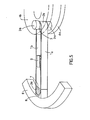
- la figure 11 est une vue en coupe longitudinale axiale d'un ensemble rotor conforme à la présente invention
- la figure 12 en est une vue du dessus ;
- la figure 13 est une vue en coupe longitudinale axiale d'une variante de réalisation d'un ensemble rotor selon l'invention
- la figures 14 est une vue de détail représentant, en coupe longitudinale axiale, une variante de réalisation de l'invention, dans laquelle on utilise avantageusement des matériaux dont les modules d'élasticité longitudinaux E et les masses spécifiques f conduisent à des valeurs différentes du rapport f pour les bras d'une part et la jante d'autre part ;
- la figure 15 est une vue de détail représentant une autre variante de réalisation dans laquelle l'extrémité du bras vient porter contre la jante par l'intermédiaire d'un matériau permettant d'assurer la compatibilité de la liaison entre la jante qui subit un allongement circonférentiel important et la pièce d'extrémité du bras ;
- les figures 16, 17 et 18 sont des schémas explicatifs permettant de montrer trois modes de réalisation possibles du montage d'un rotor selon l'invention par rapport au bâti, au moyen, par exemple de roulements à billes ou d'autres types de paliers.
- FIG. 1 is an explanatory diagram of the basic problems posed by the structure of high speed rotors, while
- Figures 2, 3 and 4 are explanatory diagrams to show the evolution of the state of prior art, developed by the Applicant to solve part of the aforementioned problems posed by high speed rotors;
- Otherwise :
- Figures 5 and 6 are perspective views showing two possible embodiments of the basic principle of an arm, rim, hub assembly whose components are combined in accordance with the present invention;
- Figure 7 is a detailed perspective view showing the part of the continuous central ring forming part of the hub which must serve as a support at the end of the arm, in the embodiment of Figure 6;
- Figure 8 is a detailed perspective view of an alternative embodiment of the junction between the end of the arm and the rim;
- Figures 9 and 10 are perspective views showing a possible alternative embodiment of the central ring forming part of the hub, respectively during its assembly and once completed, this ring can be used when the arm cannot be opened. one of its ends for reasons of mechanical stress levels;
- FIG. 11 is a view in axial longitudinal section of a rotor assembly according to the present invention
- Figure 12 is a top view;
- FIG. 13 is a view in axial longitudinal section of an alternative embodiment of a rotor assembly according to the invention
- FIGS. 14 is a detailed view showing, in axial longitudinal section, an alternative embodiment of the invention, in which materials are advantageously used whose longitudinal elastic moduli E and the specific masses f lead to values different from the ratio f for the arms on the one hand and the rim on the other hand;
- Figure 15 is a detail view showing another alternative embodiment in which the end the arm comes to bear against the rim by means of a material making it possible to ensure the compatibility of the connection between the rim which undergoes a significant circumferential elongation and the end piece of the arm;
- Figures 16, 17 and 18 are explanatory diagrams for showing three possible embodiments of the mounting of a rotor according to the invention relative to the frame, by means, for example of ball bearings or other types of bearings .
D'une façon générale, dans la solution conforme à la présente invention la liaison entre la jante et le moyeu est réalisée au moyen de bras ou rayons constitués de la manière exposée ci-après à partir de l'utilisation principale mais non exclusive de matériaux composites filamentaires.In general, in the solution according to the present invention, the connection between the rim and the hub is carried out by means of arms or spokes formed in the manner described below from the main but not exclusive use of materials. filamentary composites.
Plus particulièrement, chaque bras est constitué, comme cela apparaît sur les figures 5, 6 et 7, par bobinage, sur un mandrin adapté, de matériaux composites filamentaires tels que fibre de verre, de carbone, de polymères, de bore, d'acier, etc. qui donne audit bras la forme générale d'une boucle allongée dont les deux côtés comportent des parties rectilignes.More particularly, each arm is made up, as shown in FIGS. 5, 6 and 7, by winding, on a suitable mandrel, of filamentary composite materials such as fiberglass, carbon, polymers, boron, steel , etc. which gives said arm the general shape of an elongated loop whose two sides have rectilinear parts.
En d'autres termes, le bras est constitué de deux plaques minces la et lb réunies à leurs extrémités par des éléments arrondis 2a et 2b, étant à noter que ces éléments arrondis peuvent être circulaires mais peuvent avantageusement aussi avoir une forme allongée optimisée, dite forme de Cornu, afin d'améliorer la répartition des contraintes mécaniques dans la zone de liaison entre le bras et la pièce avec laquelle il est en contact.In other words, the arm consists of two
Si l'on compare les figures 5 et 6, on constate que le plan médian de symétrie longitudinale des bras peut, soit contenir l'axe de rotation du rotor (figure 5), soit être perpendiculaire à cet axe de rotation (figure 6).If we compare Figures 5 and 6, we see that the median plane of longitudinal symmetry of the arms can either contain the axis of rotation of the rotor (Figure 5), or be perpendicular to this axis of rotation (Figure 6) .
Dans le cas de la figure 5, l'extrémité allongée 2b de chaque bras situé du côté du centre du volant vient porter pour son appui sur une pièce d'adaptation 3 parallèle à l'axe de rotation de l'ensemble et fixée, de part et d'autre du bras, par ses deux extrémités 3a et 3b dans deux flasques 4a et 4b constituant une partie du moyeu. Cet ensemble de fixation est évidemment dimensionné de façon à pouvoir tenir la force centrifuge appliquée au bras et comporte dans sa partie centrale une surface d'appui complémentaire de l'extrémité 2b du bras.In the case of FIG. 5, the
Dans le cas où le plan des bras est perpendiculaire à l'axe représenté sur la figure 6, l'extrémité 2b de chaque bras située du côté du centre du volant vient porter, pour son appui, sur une couronne circulaire 5 qui tient l'ensemble des bras contre la force centrifuge qui les sollicite et qui les centre, cette couronne circulaire constituant une partie du moyeu du volant. La liaison entre les bras et la couronne est assurée avantageusement par collage.In the case where the plane of the arms is perpendicular to the axis shown in FIG. 6, the
Pour éviter d'avoir à aménager à l'extrémité 2b du bras une pièce supplémentaire destinée à adapter la forme du bras en cette extrémité pour son appui sur une couronne circulaire, on peut avantageusement adopter la réalisation représentée sur la figure 7. Suivant cette dernière, la couronne circulaire 5 comporte, aux endroits où les différents bras doivent venir s'appliquer, des portées 5a qui sont usinées exactement à la forme interne d'appui de l'extrémité 2b du bras.To avoid having to arrange at the
Dans les deux formes de réalisation des figures 5 et 6, chaque bras reçoit, au niveau de l'extrémité 2a située du côté de la jante 6, d'une part une pièce interne 7 dont la masse est définie de façon à provoquer un allongement du bras adapté à celui de la jante 6, d'autre part, une seconde pièce externe 8 qui a pour effet d'assurer l'adaptation des formes permettant une liaison par collage avec la jante 6.In the two embodiments of Figures 5 and 6, each arm receives, at the
Dans les deux formes de réalisation des figures 5 et 6, chacun des bras peut avantageusement être équipé de raidisseurs, tel que celui représenté en 9, qui ont pour effet d'augmenter la raideur de la fixation de la jante par rapport au moyeu, soit en couple si la forme de réalisation de la figure 5 est mise en oeuvre, soit dans le sens axial si la forme de réalisation de la figure 6 est appliquée.In the two embodiments of FIGS. 5 and 6, each of the arms can advantageously be equipped with stiffeners, such as that shown in 9, which have the effect of increasing the stiffness of the attachment of the rim relative to the hub, either in torque if the embodiment of Figure 5 is implemented, or in the axial direction if the embodiment of Figure 6 is applied.
Dans la forme de réalisation de la figure 6, il est important de noter que le fait que le bras puisse être ouvert ou non ouvert à l'une de ses extrémités et plus particulièrement à l'extrémité côté jante, entraîne les conséquences ci-après exposées.In the embodiment of Figure 6, it is important to note that the fact that the arm can be open or unopened at one of its ends and more particularly at the rim side end, has the consequences set out below.
Dans le cas où l'extrémité du bras peut être ouverte, notamment côté jante, on peut, d'une part, utiliser une couronne centrale circulaire 5 continue, d'autre part, tronquer complètement l'extrémité arrondie 2a et faire porter directement la pièce interne 7 contre la jante 6, comme représenté sur la figure 8. Cette réalisation permet d'éliminer la seconde pièce d'adaptation 8 et d'obtenir une parfaite liaison par collage entre bras et jante.In the case where the end of the arm can be opened, in particular on the rim side, it is possible, on the one hand, to use a continuous circular
Si, par contre, le bras ne peut pas être ouvert à une extrémité pour des raisons de niveaux de contraintes mécaniques, on ne peut évidemment pas adopter la réalisation de la figure 8 mais, de plus, la couronne centrale de fixation doit pouvoir s'ouvrir lors du montage des bras.If, on the other hand, the arm cannot be opened at one end for reasons of levels of mechanical stress, it is obviously not possible to adopt the embodiment of FIG. 8 but, moreover, the central fixing ring must be able to open when mounting the arms.
On peut alors avantageusement appliquer à cet effet la forme de réalisation, schématisée sur les figures 9 et 10. Dans ce cas, la couronne centrale de fixation est constituée d'un nombre approprié de couronnes élémentaires minces 9a, 9b...9n assemblées entre elles par collage. Par ailleurs, chacune des couronnes élémentaires est constituée de deux demi-secteurs minces 9a1, 9a2 pour la couronne élémentaire 9a et 9b1, 9b2 pour la couronne élémentaire 9b. Les demi-secteurs constituant une couronne élémentaire sont assemblés par collage, étant à noter que les lignes de collage 9a3 de la couronne élémentaire 9a et les lignes de collage 9b3 de la couronne élémentaire 9b sont décalées de 90° les unes par rapport aux autres lorsque les couronnes élémentaires 9a et 9b sont assemblées entre elles par collage et ainsi de suite jusqu'à l'assemblage de la couronne élémentaire 9n.One can then advantageously apply for this purpose the embodiment, shown diagrammatically in FIGS. 9 and 10. In this case, the central fixing ring consists of an appropriate number of thin
Le nombre des bras peut être adapté à chaque configuration définitive du rotor à haute vitesse. C'est ainsi que si la jante a une certaine hauteur, on sera amené à utiliser au moins deux ensembles de bras, un à chaque extrémité de la jante, ou même un plus grand nombre d'ensembles de bras selon la hauteur de ladite jante.The number of arms can be adapted to each final configuration of the high speed rotor. Thus, if the rim has a certain height, we will have to use at least two sets of arms, one at each end of the rim, or even a greater number of sets of arms depending on the height of said rim. .
On a représenté sur les figures 11 et 12, à titre d'exemple nullement limitatif, comment peut être réalisé un rotor à haute vitesse pour volant d'inertie conforme à la présente invention.There is shown in Figures 11 and 12, by way of non-limiting example, how can be produced a high speed rotor for flywheel according to the present invention.
La hauteur de la jante 6 nécessite, en l'occurrence, l'emploi de deux ensembles de bras 10a et 10b montés aux deux extrémités de ladite jante. Chaque ensemble est ici constitué de huit bras appareillés par paires de bras opposés : lla, llb, 12a, 12b, 13a, 13b et 14a, 14b. Chacun des bras est ici du type de la figure 5 et la couronne centrale est ici constituée de deux flasques 4a et 4b réunis entre eux par des pièces d'adaptation 3, 3a, 3b sur lesquelles portent les extrémités internes 2b des bras. Le flasque interne 4a fait partie du moyeu 16. L'arbre central 18 est ici tournant et solidaire dudit moyeu 16. Des roulements 19 permettent de monter l'ensemble dans un bâti comme on le verra en détail.The height of the
Par ailleurs, il est bien évident que l'on pourrait utiliser tout aussi bien des bras du type de celui de la figure 6 comme cela est schématisé à titre d'exemple sur la figure 13.Furthermore, it is quite obvious that arms of the type of that of FIG. 6 could be used just as well, as shown schematically by way of example in FIG. 13.
Dans ce cas la couronne centrale circulaire de fixation 5 est continue. Cette couronne qui fait partie du moyeu est fixée par des attaches 15 entre l'épaulement 16a de la partie médiane du moyeu 16 et une couronne extérieure 17. L'arbre central 18 est encore ici solidaire du moyeu 16 et des roulements 19 permettent de monter l'ensemble dans un bâti.In this case the central
L'on pourrait encore utiliser des bras du type de celui de la figure 8. C'est ainsi que l'on peut mettre en valeur la caractéristique de l'invention suivant laquelle on utilise pour la constitution des bras des matériaux composites filamentaires. Dans cette éventualité on peut avantageusement appliquer la variante de réalisation représentée sur la figure 14 dans laquelle l'extrémité du bras, côté jante, est collée directement contre la jante et dans laquelle on utilise avantageusement des matériaux dont les modules d'élasticité longitudinaux E et les masses spécifiques e conduisent à des valeurs différentes du rapport E pour les bras d'une part et la jante d'autre part.Arms of the type of that of FIG. 8 could also be used. This is how one can enhance the characteristic of the invention according to which filamentary composite materials are used for the constitution of the arms. In this eventuality, it is advantageously possible to apply the variant embodiment shown in FIG. 14 in which the end of the arm, on the rim side, is glued directly against the rim and in which materials are advantageously used, the longitudinal elastic modules E and the masses specific e lead to different values of the ratio E for the arms on the one hand and the rim on the other.
Pour assurer la compatibilité de la liaison entre la jante qui subit un allongement circonférentiel important et la pièce d'extrémité du bras on peut avantageusement adopter le mode de réalisation représenté sur la figure 15.To ensure the compatibility of the connection between the rim which undergoes a significant circumferential elongation and the end piece of the arm, it is advantageous to adopt the embodiment shown in FIG. 15.
Dans ce cas, le bras est par exemple du type de celui représenté sur la figure 5 dans lequel la pièce d'adaptation 8 est ici remplacée par une pièce 20 qui englobe l'extrémité 2a du bras contenant la masse interne 7, cette pièce 20 étant munie à son extrémité en contact avec la jante 6 d'une plaque 21 constituée d'un matériau dont les caractéristiques d'allongement sont telles qu'il puisse rester d'un côté solidarisé avec la pièce 20 sans allongement tangentiel au niveau de ce contact et de l'autre côté rester solidarisé avec la jante en acceptant son allongement tangentiel, cela quel que soit cet allongement, dans toute la plage de vitesse. Cette plaque 21 peut être constituée d'une résine ou d'un élastomère avantageusement armé de fibre de verre, de carbone, de polymère, etc. La plaque 21 est ainsi collée d'un côté sur la pièce 20 et de l'autre sur la jante 6. Suivant une variante non représentée, la pièce 20 peut être munie à son extrémité d'un empilage de feuilles minces d'un matériau capable d'un grand allongement, tel que "Mylar" "Kapton" ou analogues auto-adhésif sur ses deux faces ou avec encollage des feuilles entre elles et sur la jante et la pièce 20.In this case, the arm is for example of the type of that shown in FIG. 5 in which the
On a décrit précédemment en référence aux figures 11 et 12 et 13 comment pouvait être réalisé conformément à l'invention un ensemble rotor à haute vitesse plus particulièrement pour volant d'inertie.We have previously described with reference to FIGS. 11 and 12 and 13 how a high speed rotor assembly could be produced in accordance with the invention, more particularly for a flywheel.
On va maintenant décrire, succinctement, en se référant aux figures très schématiques 16, 17 et 18, trois modes de réalisation possibles du montage d'un rotor selon l'invention désigné par la référence générale R par rapport à un bâti formant carter désigné par la référence générale B, au moyen de paliers mécaniques, par exemple des roulements à billes ou analogues.We will now describe, succinctly, with reference to very schematic figures 16, 17 and 18, three possible embodiments of the mounting of a rotor according to the invention designated by the general reference R with respect to a frame forming a housing designated by the general reference B, by means of mechanical bearings, for example ball bearings or the like.
Il est bien évident que le problème serait du même ordre en remplaçant les paliers mécaniques en question par des paliers magnétiques, moyennant les adaptations électromagnétiques inhérentes auxdits paliers magnétiques.It is quite obvious that the problem would be of the same order by replacing the mechanical bearings in question by magnetic bearings, by means of the electromagnetic adaptations inherent in said magnetic bearings.
Ceci étant, il y a lieu de noter l'existence de deux types de suspension, à savoir : la suspension avec arbre central tournant 18t des figures 16 et 17 et la suspension avec arbre central fixe 18f de la figure 18.However, it should be noted that there are two types of suspension, namely: the suspension with rotating
Dans le cas de la figure 16, l'arbre central 18t qui est solidaire du moyeu du rotor R est monté de part et d'autre dudit rotor dans les éléments mobiles de deux roulements 19 dont les éléments fixes sont solidaires de deux cylindres 22 constitutifs du bâti.In the case of FIG. 16, the
Bien évidemment l'un au moins des cylindres 22, le supérieur par exemple, sert de carter au moteur-générateur électrique d'un type quelconque connu dont les éléments électromagnétiques fixes 23 sont solidaires du cylindre 22 et les éléments électromagnétiques mobiles 24 solidaires de l'arbre central tournant 18t.Obviously at least one of the
Suivant une variante, on peut bien entendu agencer un moteur dans le cylindre supérieur et un générateur dans le cylindre inférieur.According to a variant, it is of course possible to arrange a motor in the upper cylinder and a generator in the lower cylinder.
Sans entrer dans des détails inutiles qui ne font pas partie de l'invention, on rappellera brièvement que le moteur permet d'entraîner le rotor formant volant d'inertie à haute vitesse pour stocker de l'énergie sous forme cinétique. Cette énergie cinétique est restituée sous forme électrique par le générateur ou même sous forme mécanique par l'arbre tournant entraîné par le rotor sur son énergie cinétique.Without going into unnecessary details which are not part of the invention, it will be recalled briefly that the motor makes it possible to drive the rotor forming a flywheel at high speed to store energy in kinetic form. This kinetic energy is returned in electrical form by the generator or even in mechanical form by the rotating shaft driven by the rotor on its kinetic energy.
Suivant la variante de réalisation représentée sur la figure 17, l'arbre central tournant 18t sur lequel est calé le rotor R formant volant d"inertie est supporté en porte-à-faux par deux roulements 19 montés aux deux extrémités d'un cylindre 22 monté à la partie supérieure du bâti. Bien entendu un moteur-générateur électrique 23-24 est monté dans ledit cylindre 22 et l'ensemble fonctionne de la même manière que la forme de réalisation de la figure 16 décrite précédemment.According to the alternative embodiment shown in FIG. 17, the rotating
Dans le cas de la figure 18, la suspension est ici à arbre central fixe 18f.In the case of FIG. 18, the suspension here has a fixed
Dans cette forme de réalisation, l'arbre 18f est fixé à ses deux extrémités dans l'axe du bâti B, tandis que le rotor R est solidaire d'un cylindre central 22 lui-même solidaire des éléments mobiles des roulements 19 dont les éléments fixes sont solidaires de l'arbre central fixe 18f.In this embodiment, the
Bien entendu, dans ce cas les éléments électromagnétiques fixes 23 du moteur-générateur sont solidaires de l'arbre central fixe 18t alors que les éléments électromagnétiques mobiles 24 de ce moteur sont solidaires du rotor R.Of course, in this case the fixed
Bien évidemment, l'ensemble de la figure 18 fonctionne de manière tout à fait analogue à celle décrite précédemment.Obviously, the assembly of FIG. 18 operates in a manner completely similar to that described above.
Il va de soi que la présente invention n'a été décrite et représentée qu'à titre d'exemple préférentiel et qu'on pourra y apporter des équivalences techniques dans ses éléments constitutifs sans pour autant sortir du cadre de l'invention défini dans les revendications annexées.It goes without saying that the present invention has only been described and shown as a preferred example and that technical equivalences may be made to it in its constituent elements without going beyond the ambit of the invention defined in the appended claims.
Claims (15)
Priority Applications (1)
| Application Number | Priority Date | Filing Date | Title |
|---|---|---|---|
| AT82400574T ATE15714T1 (en) | 1981-04-14 | 1982-03-30 | FAST ROTATING ROTOR ESPECIALLY FOR FLYWHEEL. |
Applications Claiming Priority (2)
| Application Number | Priority Date | Filing Date | Title |
|---|---|---|---|
| FR8107465A FR2503808A1 (en) | 1981-04-14 | 1981-04-14 | METHOD FOR PRODUCING A HIGH-SPEED ROTOR AND ROTOR USING SAID METHOD |
| FR8107465 | 1981-04-14 |
Publications (2)
| Publication Number | Publication Date |
|---|---|
| EP0063074A1 true EP0063074A1 (en) | 1982-10-20 |
| EP0063074B1 EP0063074B1 (en) | 1985-09-18 |
Family
ID=9257382
Family Applications (1)
| Application Number | Title | Priority Date | Filing Date |
|---|---|---|---|
| EP82400574A Expired EP0063074B1 (en) | 1981-04-14 | 1982-03-30 | High speed rotor especially for flywheel |
Country Status (7)
| Country | Link |
|---|---|
| US (1) | US4502349A (en) |
| EP (1) | EP0063074B1 (en) |
| JP (1) | JPS57190145A (en) |
| AT (1) | ATE15714T1 (en) |
| CA (1) | CA1166481A (en) |
| DE (1) | DE3266293D1 (en) |
| FR (1) | FR2503808A1 (en) |
Cited By (1)
| Publication number | Priority date | Publication date | Assignee | Title |
|---|---|---|---|---|
| EP0210563A2 (en) * | 1985-07-23 | 1987-02-04 | E.I. Du Pont De Nemours And Company | Centrifuge rotor |
Families Citing this family (15)
| Publication number | Priority date | Publication date | Assignee | Title |
|---|---|---|---|---|
| FR2574491B1 (en) * | 1984-12-07 | 1989-01-06 | Europ Agence Spatiale | ENERGY STORAGE WHEEL |
| US4991462A (en) * | 1985-12-06 | 1991-02-12 | E. I. Du Pont De Nemours And Company | Flexible composite ultracentrifuge rotor |
| US4817453A (en) * | 1985-12-06 | 1989-04-04 | E. I. Dupont De Nemours And Company | Fiber reinforced centrifuge rotor |
| US4835827A (en) * | 1987-09-08 | 1989-06-06 | United Technologies Corporation | Method of balancing a rotor |
| US5562584A (en) * | 1989-08-02 | 1996-10-08 | E. I. Du Pont De Nemours And Company | Tension band centrifuge rotor |
| US5545118A (en) * | 1989-08-02 | 1996-08-13 | Romanauskas; William A. | Tension band centrifuge rotor |
| WO1992015930A1 (en) * | 1991-03-01 | 1992-09-17 | E.I. Du Pont De Nemours And Company | Tension band centrifuge rotor |
| US5452625A (en) * | 1993-09-29 | 1995-09-26 | United Technologies Corporation | Energy storage flywheel device |
| US8147393B2 (en) * | 2009-01-19 | 2012-04-03 | Fiberlite Centrifuge, Llc | Composite centrifuge rotor |
| US8147392B2 (en) * | 2009-02-24 | 2012-04-03 | Fiberlite Centrifuge, Llc | Fixed angle centrifuge rotor with helically wound reinforcement |
| US8328708B2 (en) * | 2009-12-07 | 2012-12-11 | Fiberlite Centrifuge, Llc | Fiber-reinforced swing bucket centrifuge rotor and related methods |
| CN102624110B (en) * | 2011-01-28 | 2013-12-04 | 深圳飞能能源有限公司 | High-speed motor |
| CN102624141B (en) * | 2011-01-28 | 2014-03-19 | 深圳飞能能源有限公司 | High-speed flywheel battery rotor |
| US10050491B2 (en) | 2014-12-02 | 2018-08-14 | Management Services Group, Inc. | Devices and methods for increasing energy and/or power density in composite flywheel energy storage systems |
| KR20210126682A (en) * | 2019-02-11 | 2021-10-20 | 앰버 카이네틱스, 인크. | Laminate lamellar rotor |
Citations (6)
| Publication number | Priority date | Publication date | Assignee | Title |
|---|---|---|---|---|
| FR2082274A5 (en) * | 1970-03-09 | 1971-12-10 | Aerospatiale | Ultracentrifuge rotor - hub spider and wall assembly of high rigidity to weight ratio |
| FR2282737A1 (en) * | 1974-08-22 | 1976-03-19 | Inst Rech Transports | WHEEL STRUCTURE ADAPTED TO LARGE ANGULAR SPEEDS AND METHOD OF MANUFACTURING THE SAME |
| US4176563A (en) * | 1976-10-27 | 1979-12-04 | Electric Power Research Institute | Inertial energy storage rotor with tension-balanced catenary spokes |
| FR2434968A1 (en) * | 1978-08-29 | 1980-03-28 | Aerospatiale | INERTIAL PROCESS OF CENTRAL OF A CONSTANTLY CIRCULAR RIM ON ITS HUB AND CORRESPONDING ROTARY DEVICE |
| FR2436267A1 (en) * | 1978-09-13 | 1980-04-11 | Swartout Bruce | RIM FOR FLYWHEEL |
| FR2458005A1 (en) * | 1979-05-29 | 1980-12-26 | Aerospatiale | METHOD FOR PRODUCING A SUBCIRCULAR TYPE ROTOR AND ROTORS IMPLEMENTING THIS METHOD, IN PARTICULAR FLYWHEEL ROTORS |
Family Cites Families (3)
| Publication number | Priority date | Publication date | Assignee | Title |
|---|---|---|---|---|
| CH447041A (en) * | 1965-06-21 | 1968-03-15 | Ebauches Sa | Balancing device of a rotating or oscillating handwheel of a clockwork movement |
| US3964341A (en) * | 1974-03-18 | 1976-06-22 | The Johns Hopkins University | Multi-ring filament rotor |
| US4036080A (en) * | 1974-11-29 | 1977-07-19 | The Garrett Corporation | Multi-rim flywheel |
-
1981
- 1981-04-14 FR FR8107465A patent/FR2503808A1/en active Granted
-
1982
- 1982-03-30 AT AT82400574T patent/ATE15714T1/en not_active IP Right Cessation
- 1982-03-30 DE DE8282400574T patent/DE3266293D1/en not_active Expired
- 1982-03-30 EP EP82400574A patent/EP0063074B1/en not_active Expired
- 1982-03-31 CA CA000400041A patent/CA1166481A/en not_active Expired
- 1982-04-09 US US06/367,124 patent/US4502349A/en not_active Expired - Fee Related
- 1982-04-13 JP JP57061655A patent/JPS57190145A/en active Pending
Patent Citations (6)
| Publication number | Priority date | Publication date | Assignee | Title |
|---|---|---|---|---|
| FR2082274A5 (en) * | 1970-03-09 | 1971-12-10 | Aerospatiale | Ultracentrifuge rotor - hub spider and wall assembly of high rigidity to weight ratio |
| FR2282737A1 (en) * | 1974-08-22 | 1976-03-19 | Inst Rech Transports | WHEEL STRUCTURE ADAPTED TO LARGE ANGULAR SPEEDS AND METHOD OF MANUFACTURING THE SAME |
| US4176563A (en) * | 1976-10-27 | 1979-12-04 | Electric Power Research Institute | Inertial energy storage rotor with tension-balanced catenary spokes |
| FR2434968A1 (en) * | 1978-08-29 | 1980-03-28 | Aerospatiale | INERTIAL PROCESS OF CENTRAL OF A CONSTANTLY CIRCULAR RIM ON ITS HUB AND CORRESPONDING ROTARY DEVICE |
| FR2436267A1 (en) * | 1978-09-13 | 1980-04-11 | Swartout Bruce | RIM FOR FLYWHEEL |
| FR2458005A1 (en) * | 1979-05-29 | 1980-12-26 | Aerospatiale | METHOD FOR PRODUCING A SUBCIRCULAR TYPE ROTOR AND ROTORS IMPLEMENTING THIS METHOD, IN PARTICULAR FLYWHEEL ROTORS |
Cited By (2)
| Publication number | Priority date | Publication date | Assignee | Title |
|---|---|---|---|---|
| EP0210563A2 (en) * | 1985-07-23 | 1987-02-04 | E.I. Du Pont De Nemours And Company | Centrifuge rotor |
| EP0210563A3 (en) * | 1985-07-23 | 1987-12-02 | E.I. Du Pont De Nemours And Company | Centrifuge rotor |
Also Published As
| Publication number | Publication date |
|---|---|
| DE3266293D1 (en) | 1985-10-24 |
| US4502349A (en) | 1985-03-05 |
| CA1166481A (en) | 1984-05-01 |
| FR2503808B1 (en) | 1983-06-24 |
| JPS57190145A (en) | 1982-11-22 |
| FR2503808A1 (en) | 1982-10-15 |
| ATE15714T1 (en) | 1985-10-15 |
| EP0063074B1 (en) | 1985-09-18 |
Similar Documents
| Publication | Publication Date | Title |
|---|---|---|
| EP0063074B1 (en) | High speed rotor especially for flywheel | |
| EP3212960B1 (en) | Flywheel intended for energy storage | |
| EP0424267B1 (en) | Rotary visco-elastic return and lag-damping device for a rotorcraft blade, and rotor head | |
| EP0493145A1 (en) | Rotor hub for a rotorcraft | |
| EP0608675B1 (en) | High rotating speed, high power electrical motor | |
| FR3013529A1 (en) | BLINDS FOR MAINTAINING MAGNETS | |
| EP0868770A1 (en) | Basic module for a discoidal electric machine, and corresponding electric machine | |
| FR3027468A1 (en) | DISCOID ROTOR WITH COMPOSITE STRUCTURE | |
| EP0187080B1 (en) | Energy storage wheel | |
| EP3811498A1 (en) | Rotor for an electromagnetic motor or generator with tapered branches | |
| EP2019220B1 (en) | Flexible disc, flexible coupling provided with such a flexible disc, mounting flange provided with such a flexible coupling and transmission shaft fitted with such a mounting flange | |
| FR2629958A1 (en) | ROTOR FOR ELECTRIC MACHINE EXCITED BY PERMANENT MAGNETS | |
| EP0308369A1 (en) | Permanent-magnet rotor | |
| EP0538088B1 (en) | Multiblade rotor, in particular for helicopter anti-torque rotor, and its manufacturing process | |
| FR3031497A1 (en) | ROTOR OF GIRAVION COMPRISING A HUB IN COMPOSITE MATERIALS FROM CARBON FIBER TISSUES POWDERED WITH A THERMOPLASTIC RESIN | |
| FR2690018A1 (en) | Piezoelectric modular motor with stator having two active faces - has both faces excited by transducers having two active faces insulated by coaxial element | |
| FR3033095A1 (en) | DEVICE FOR FIXING MAGNETS IN A ROTOR OF A DISCOIDED ELECTRIC MACHINE. | |
| FR2894733A1 (en) | METHOD FOR MANUFACTURING ROTOR AND ROTOR OF ELECTRIC ROTATING MACHINE | |
| EP2160584B1 (en) | Transmission shaft attachment tooling and balancing stand comprising such tooling | |
| CH643041A5 (en) | SUBCIRCULAR ROTOR. | |
| EP4115498A1 (en) | Rotor for an axial flux electromagnetic machine | |
| EP1856313A1 (en) | Anvil wheel comprising a mounted band | |
| FR3040566A1 (en) | DEVICE FOR GENERATING ELECTRIC ENERGY FROM THE ROTATION OF A WHEEL OF A VEHICLE | |
| FR3121295A1 (en) | rotor for an axial flux electric machine, methods of assembling and disassembling such a rotor | |
| WO2020020993A1 (en) | Claw rotor comprising inter-claw magnetic elements for a rotating electric machine |
Legal Events
| Date | Code | Title | Description |
|---|---|---|---|
| PUAI | Public reference made under article 153(3) epc to a published international application that has entered the european phase |
Free format text: ORIGINAL CODE: 0009012 |
|
| AK | Designated contracting states |
Designated state(s): AT BE CH DE GB IT NL SE |
|
| 17P | Request for examination filed |
Effective date: 19821129 |
|
| ITF | It: translation for a ep patent filed |
Owner name: BARZANO' E ZANARDO ROMA S.P.A. |
|
| GRAA | (expected) grant |
Free format text: ORIGINAL CODE: 0009210 |
|
| AK | Designated contracting states |
Designated state(s): AT BE CH DE GB IT LI NL SE |
|
| REF | Corresponds to: |
Ref document number: 15714 Country of ref document: AT Date of ref document: 19851015 Kind code of ref document: T |
|
| REF | Corresponds to: |
Ref document number: 3266293 Country of ref document: DE Date of ref document: 19851024 |
|
| PLBE | No opposition filed within time limit |
Free format text: ORIGINAL CODE: 0009261 |
|
| STAA | Information on the status of an ep patent application or granted ep patent |
Free format text: STATUS: NO OPPOSITION FILED WITHIN TIME LIMIT |
|
| 26N | No opposition filed | ||
| PGFP | Annual fee paid to national office [announced via postgrant information from national office to epo] |
Ref country code: SE Payment date: 19910312 Year of fee payment: 10 |
|
| PGFP | Annual fee paid to national office [announced via postgrant information from national office to epo] |
Ref country code: GB Payment date: 19910321 Year of fee payment: 10 |
|
| ITTA | It: last paid annual fee | ||
| PGFP | Annual fee paid to national office [announced via postgrant information from national office to epo] |
Ref country code: NL Payment date: 19910331 Year of fee payment: 10 |
|
| PGFP | Annual fee paid to national office [announced via postgrant information from national office to epo] |
Ref country code: CH Payment date: 19910411 Year of fee payment: 10 |
|
| PGFP | Annual fee paid to national office [announced via postgrant information from national office to epo] |
Ref country code: DE Payment date: 19910514 Year of fee payment: 10 Ref country code: BE Payment date: 19910514 Year of fee payment: 10 |
|
| PGFP | Annual fee paid to national office [announced via postgrant information from national office to epo] |
Ref country code: AT Payment date: 19910528 Year of fee payment: 10 |
|
| PG25 | Lapsed in a contracting state [announced via postgrant information from national office to epo] |
Ref country code: GB Effective date: 19920330 Ref country code: AT Effective date: 19920330 |
|
| PG25 | Lapsed in a contracting state [announced via postgrant information from national office to epo] |
Ref country code: SE Effective date: 19920331 Ref country code: LI Effective date: 19920331 Ref country code: CH Effective date: 19920331 Ref country code: BE Effective date: 19920331 |
|
| BERE | Be: lapsed |
Owner name: SOC. NATIONALE INDUSTRIELLE AEROSPATIALE Effective date: 19920331 |
|
| PG25 | Lapsed in a contracting state [announced via postgrant information from national office to epo] |
Ref country code: NL Effective date: 19921001 |
|
| NLV4 | Nl: lapsed or anulled due to non-payment of the annual fee | ||
| GBPC | Gb: european patent ceased through non-payment of renewal fee | ||
| REG | Reference to a national code |
Ref country code: CH Ref legal event code: PL |
|
| PG25 | Lapsed in a contracting state [announced via postgrant information from national office to epo] |
Ref country code: DE Effective date: 19921201 |
|
| EUG | Se: european patent has lapsed |
Ref document number: 82400574.8 Effective date: 19921005 |