EP0062962A1 - A method to be used in panoramic X-ray photography and an apparatus for carrying out the method - Google Patents
A method to be used in panoramic X-ray photography and an apparatus for carrying out the method Download PDFInfo
- Publication number
- EP0062962A1 EP0062962A1 EP82300773A EP82300773A EP0062962A1 EP 0062962 A1 EP0062962 A1 EP 0062962A1 EP 82300773 A EP82300773 A EP 82300773A EP 82300773 A EP82300773 A EP 82300773A EP 0062962 A1 EP0062962 A1 EP 0062962A1
- Authority
- EP
- European Patent Office
- Prior art keywords
- film
- ray
- patient
- ray apparatus
- relation
- Prior art date
- Legal status (The legal status is an assumption and is not a legal conclusion. Google has not performed a legal analysis and makes no representation as to the accuracy of the status listed.)
- Granted
Links
- 238000000034 method Methods 0.000 title claims description 11
- 238000010586 diagram Methods 0.000 description 2
- 230000009347 mechanical transmission Effects 0.000 description 2
- 238000003325 tomography Methods 0.000 description 2
- 230000005540 biological transmission Effects 0.000 description 1
- 230000000694 effects Effects 0.000 description 1
Images

Classifications
-
- A—HUMAN NECESSITIES
- A61—MEDICAL OR VETERINARY SCIENCE; HYGIENE
- A61B—DIAGNOSIS; SURGERY; IDENTIFICATION
- A61B6/00—Apparatus or devices for radiation diagnosis; Apparatus or devices for radiation diagnosis combined with radiation therapy equipment
- A61B6/50—Apparatus or devices for radiation diagnosis; Apparatus or devices for radiation diagnosis combined with radiation therapy equipment specially adapted for specific body parts; specially adapted for specific clinical applications
- A61B6/51—Apparatus or devices for radiation diagnosis; Apparatus or devices for radiation diagnosis combined with radiation therapy equipment specially adapted for specific body parts; specially adapted for specific clinical applications for dentistry
Definitions
- the present invention relates to a method to be used in panoramic X-ray photography by means of an X-ray apparatus which performs a rotational movement and comprises an X-ray source and a moving film, for adjusting the areas of focus to the correct point in relation to the patient before photographing is started, a method in which the patient is supported by means of support members and, for the purpose of adjustment, a sighting member is moved to the corrent point in relation to the patient.
- the invention also relates to an apparatus for carrying out this method.
- the invention relates in particular to panoramic tomography, i.e.
- Another alternative suggested in order to avoid moving the patient is to connect the suspending part of the support arm of the X-ray apparatus mechanically to the sighting device, in which case the patient is always placed in the same position by means of stationary support members, and the fine adjustment is carried out by moving the X-ray apparatus itself.
- the disadvantage of this alternative is its structurally complicated and expensive moving mechanism, as we must remember that, after the initial setting, the X-ray apparatus, in other words, the support arm, further performs the said combined linear and rotational movement.
- the speed of the film is controlled in such a manner that at each given moment it corresponds to the speed of the point being photographed, as the point is taken as projected onto the film surface.
- the object of the present invention is to eliminate the above-mentioned disadvantages of known apparatus in such a manner that the patient can also be placed in a stationary position by means of the support members of the apparatus, and that the moving part of the X-ray apparatus, for example, the support arm, can also perform the same movement without fine adjustment of the initial point before photographing is started.
- This objective is achieved by taking advantage of the effect of the film speed in relation to the object being photographed. By means of different adjustments of the film speed it is, namely, possible to move the position of the object being photographed, e.g. a denture, without moving the patient and the X-ray apparatus.
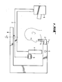
- Figure 1 is a diagrammatic representation of a side elevation of an X-ray apparatus intended for photographing a denture
- Figure 2 is a block diagram of the circuitry of the apparatus according to the invention.
- the apparatus depicted in Figure 1 includes the following parts: A position sensor 1, a sighting member 2 indicating the layer being photographed, a moving mechanism 3 for the sighting member, an image registration apparatus 4 consisting of a moving film cassette, a patient support 5 which is stationary in relation to the supporting frame, a drive motor 6 for the image registration device, a rotating support arm 7, a supporting frame 8, and an X-ray source 9.
- the support 5 can, of course, be replaceable depending on the object which is being photographed at a given time.
- That which is essential in the present invention is that the patient is always placed in a stationary position with -the aid of supporting member 5, and that the moving mechanism 3 for the sighting member does not affect the position of the support arm itself but only the control of the drive motor 6, preferably electronically.
- FIG. 2 the block diagram of the circuitry is depicted in greater detail. It thus includes a position sensor 1 connected to the sighting member, a converter 10, which can be an analog/digital converter or, for example, a voltage/ frequency converter, a transfer line 11, a computing unit 12, a microprocessor 13, and a motor control unit 14.
- a converter 10 which can be an analog/digital converter or, for example, a voltage/ frequency converter
- a transfer line 11 a computing unit 12
- microprocessor 13 a microprocessor 13
- motor control unit 14 the block diagram of the circuitry is depicted in greater detail. It thus includes a position sensor 1 connected to the sighting member, a converter 10, which can be an analog/digital converter or, for example, a voltage/ frequency converter, a transfer line 11, a computing unit 12, a microprocessor 13, and a motor control unit 14.
- the output of the position sensorl which thus indicates the place of the indicator device adjusted to the correct position in relation to the patient, can be, for example, an analog voltage signal, as is well known in the art of control techniques and electronics.
- This signal is converted in the converter 10 either to a corresponding digital signal or to a frequency signal, the frequency of which corresponds to the position of the indicator.
- the transfer line 11, which can be a suitable cable, transfers the converter output signal to the computing unit 12, which operates in conjunction with the microprocessor.
- the control programs for the drive motor 6 have been programmed into the microprocessor, and the programs are selected on the basis of the data obtained from the computing unit 12, i.e. on the basis of the actual position of the object being photographed.
- the processor can, of course, have fixed circuitry or be freely programmable.
- the motor 6 can be a step motor into which the motor control unit 14 feeds control pulses at a varying frequency controlled by the microprocessor 13. It is, of course, also possible to use as the drive motor a DC motor controlled by
Landscapes
- Health & Medical Sciences (AREA)
- Life Sciences & Earth Sciences (AREA)
- Medical Informatics (AREA)
- Engineering & Computer Science (AREA)
- Radiology & Medical Imaging (AREA)
- Biomedical Technology (AREA)
- Biophysics (AREA)
- High Energy & Nuclear Physics (AREA)
- Oral & Maxillofacial Surgery (AREA)
- Nuclear Medicine, Radiotherapy & Molecular Imaging (AREA)
- Optics & Photonics (AREA)
- Pathology (AREA)
- Dentistry (AREA)
- Physics & Mathematics (AREA)
- Heart & Thoracic Surgery (AREA)
- Molecular Biology (AREA)
- Surgery (AREA)
- Animal Behavior & Ethology (AREA)
- General Health & Medical Sciences (AREA)
- Public Health (AREA)
- Veterinary Medicine (AREA)
- Apparatus For Radiation Diagnosis (AREA)
- Radiography Using Non-Light Waves (AREA)
- Stereoscopic And Panoramic Photography (AREA)
Abstract
Description
- The present invention relates to a method to be used in panoramic X-ray photography by means of an X-ray apparatus which performs a rotational movement and comprises an X-ray source and a moving film, for adjusting the areas of focus to the correct point in relation to the patient before photographing is started, a method in which the patient is supported by means of support members and, for the purpose of adjustment, a sighting member is moved to the corrent point in relation to the patient. The invention also relates to an apparatus for carrying out this method. The invention relates in particular to panoramic tomography, i.e. photography of a patient's denture, but it can also be applied to other cases of X-ray photography in which an X-ray source and a film, situated on different sides of the patient, are rotated around the patient during the photographing, while the film is reeled forwards.
- It is known that the shape of the layer which is photographed with precision can be affected by means of the geometry of the X-ray apparatus, and, especially in panoramic tomography apparatus, by making arrangements for a combined linear and rotational movement of the support arm which supports the X-ray source and the film cassette at its opposite ends.
- In order to bring the patient and the apparatus to the correct position in relation to each other before photographing is started, it has been known to use a sighting device indicating the object to be photographed and to move the patient to the correct point by means of this sighting device. The disadvantages of this method are the structural requirements set by it on the patient-supporting members and the moving of the patient after the initial setting, resulting in the lengthening of the time used for the photographing and sometimes also in an imprecise X-ray photograph.
- Another alternative suggested in order to avoid moving the patient is to connect the suspending part of the support arm of the X-ray apparatus mechanically to the sighting device, in which case the patient is always placed in the same position by means of stationary support members, and the fine adjustment is carried out by moving the X-ray apparatus itself. The disadvantage of this alternative is its structurally complicated and expensive moving mechanism, as we must remember that, after the initial setting, the X-ray apparatus, in other words, the support arm, further performs the said combined linear and rotational movement.
- Furthermore, in panoramic X-ray photography the speed of the film is controlled in such a manner that at each given moment it corresponds to the speed of the point being photographed, as the point is taken as projected onto the film surface.
- The object of the present invention is to eliminate the above-mentioned disadvantages of known apparatus in such a manner that the patient can also be placed in a stationary position by means of the support members of the apparatus, and that the moving part of the X-ray apparatus, for example, the support arm, can also perform the same movement without fine adjustment of the initial point before photographing is started. This objective is achieved by taking advantage of the effect of the film speed in relation to the object being photographed. By means of different adjustments of the film speed it is, namely, possible to move the position of the object being photographed, e.g. a denture, without moving the patient and the X-ray apparatus.
- The main characteristics of the method according to the invention are given in accompanying Claim 1, and the characteristics of the apparatus are respectively given in Claim 3.
- The invention and its other characteristics are described below in greater detail in the form of an example and with reference to the accompanying drawings, in which
- Figure 1 is a diagrammatic representation of a side elevation of an X-ray apparatus intended for photographing a denture, and Figure 2 is a block diagram of the circuitry of the apparatus according to the invention.
- The apparatus depicted in Figure 1 includes the following parts: A position sensor 1, a sighting member 2 indicating the layer being photographed, a moving mechanism 3 for the sighting member, an image registration apparatus 4 consisting of a moving film cassette, a patient support 5 which is stationary in relation to the supporting frame, a
drive motor 6 for the image registration device, arotating support arm 7, a supportingframe 8, and anX-ray source 9. The support 5 can, of course, be replaceable depending on the object which is being photographed at a given time. - In this X-ray apparatus the
support arm 7 with itsX-ray source 9 and film 4 thus rotates during the photographing around the patient's head according to a predetermined geometry. Since, as regards this part, the apparatus is completely known for an expert in the art, reference is made here as regards its operation only by way of example to previous Finnish Patent Application No. 763569. - That which is essential in the present invention is that the patient is always placed in a stationary position with -the aid of supporting member 5, and that the moving mechanism 3 for the sighting member does not affect the position of the support arm itself but only the control of the
drive motor 6, preferably electronically. - In Figure 2, the block diagram of the circuitry is depicted in greater detail. It thus includes a position sensor 1 connected to the sighting member, a
converter 10, which can be an analog/digital converter or, for example, a voltage/ frequency converter, atransfer line 11, acomputing unit 12, amicroprocessor 13, and amotor control unit 14. - The output of the position sensorl,which thus indicates the place of the indicator device adjusted to the correct position in relation to the patient, can be, for example, an analog voltage signal, as is well known in the art of control techniques and electronics. This signal is converted in the
converter 10 either to a corresponding digital signal or to a frequency signal, the frequency of which corresponds to the position of the indicator. Thetransfer line 11, which can be a suitable cable, transfers the converter output signal to thecomputing unit 12, which operates in conjunction with the microprocessor. The control programs for thedrive motor 6 have been programmed into the microprocessor, and the programs are selected on the basis of the data obtained from thecomputing unit 12, i.e. on the basis of the actual position of the object being photographed. The processor can, of course, have fixed circuitry or be freely programmable. Themotor 6 can be a step motor into which themotor control unit 14 feeds control pulses at a varying frequency controlled by themicroprocessor 13. It is, of course, also possible to use as the drive motor a DC motor controlled by means of a varying voltage. - In currently used X-ray apparatus, mechanical transmission which changes according to the movement of the support arm is generally used for the control of the film speed. It is evident that such mechanical transmission can also be applied to the present invention in such a manner that the initial setting of the transmission ratio is carried out on the basis of the reading of the position sensor.
Claims (5)
Priority Applications (1)
| Application Number | Priority Date | Filing Date | Title |
|---|---|---|---|
| AT82300773T ATE17643T1 (en) | 1981-02-20 | 1982-02-16 | METHOD AND DEVICE FOR PANORAMIC X-RAY PHOTOGRAPHS. |
Applications Claiming Priority (2)
| Application Number | Priority Date | Filing Date | Title |
|---|---|---|---|
| FI810530A FI61767C (en) | 1981-02-20 | 1981-02-20 | Method of panoramic X-ray photography and apparatus for carrying out the method |
| FI810530 | 1981-02-20 |
Publications (2)
| Publication Number | Publication Date |
|---|---|
| EP0062962A1 true EP0062962A1 (en) | 1982-10-20 |
| EP0062962B1 EP0062962B1 (en) | 1986-01-29 |
Family
ID=8514154
Family Applications (1)
| Application Number | Title | Priority Date | Filing Date |
|---|---|---|---|
| EP82300773A Expired EP0062962B1 (en) | 1981-02-20 | 1982-02-16 | A method to be used in panoramic x-ray photography and an apparatus for carrying out the method |
Country Status (6)
| Country | Link |
|---|---|
| US (1) | US4449225A (en) |
| EP (1) | EP0062962B1 (en) |
| JP (1) | JPS57155532A (en) |
| AT (1) | ATE17643T1 (en) |
| DE (1) | DE3268728D1 (en) |
| FI (1) | FI61767C (en) |
Cited By (2)
| Publication number | Priority date | Publication date | Assignee | Title |
|---|---|---|---|---|
| EP0499595A1 (en) * | 1991-02-15 | 1992-08-19 | Planmeca Oy | Method and apparatus for panoramic radiography |
| EP0512964A1 (en) * | 1991-05-06 | 1992-11-11 | Planmeca Oy | Method and apparatus for panoramic radiography |
Families Citing this family (2)
| Publication number | Priority date | Publication date | Assignee | Title |
|---|---|---|---|---|
| FI84016C (en) * | 1989-03-21 | 1991-10-10 | Instrumentarium Oy | FOERSKJUTNINGSFOERFARANDE OCH ARRANGEMANG FOER FILMKASETTENHET TILL PANORAMAROENTGENANORDNING. |
| US5761376A (en) * | 1997-05-05 | 1998-06-02 | General Electric Company | System and method of motor control |
Citations (4)
| Publication number | Priority date | Publication date | Assignee | Title |
|---|---|---|---|---|
| US4145611A (en) * | 1976-12-10 | 1979-03-20 | Den-Tal-Ez Mfg. Co. | X-ray source moving mechanism intended for panoramic radiography |
| EP0002706A1 (en) * | 1977-12-27 | 1979-07-11 | Siemens Aktiengesellschaft | Diagnostic apparatus for dental X-raying |
| NL7904882A (en) * | 1979-06-22 | 1980-12-24 | Philips Nv | X=ray machine for panoramic pictures of jaw and teeth set - has patient positioner and support arm for source and film on suspension with two drives |
| EP0035307A2 (en) * | 1980-03-01 | 1981-09-09 | Philips Patentverwaltung GmbH | Dental tomography apparatus |
Family Cites Families (2)
| Publication number | Priority date | Publication date | Assignee | Title |
|---|---|---|---|---|
| JPS52103988A (en) * | 1976-02-25 | 1977-08-31 | Morita Mfg | Method and device for taking curved sectional plane of xxray |
| JPS5945383B2 (en) * | 1979-09-20 | 1984-11-06 | 株式会社モリタ製作所 | Dental full jaw X-ray device |
-
1981
- 1981-02-20 FI FI810530A patent/FI61767C/en not_active IP Right Cessation
-
1982
- 1982-02-16 EP EP82300773A patent/EP0062962B1/en not_active Expired
- 1982-02-16 US US06/348,996 patent/US4449225A/en not_active Expired - Lifetime
- 1982-02-16 AT AT82300773T patent/ATE17643T1/en not_active IP Right Cessation
- 1982-02-16 DE DE8282300773T patent/DE3268728D1/en not_active Expired
- 1982-02-19 JP JP57026725A patent/JPS57155532A/en active Pending
Patent Citations (4)
| Publication number | Priority date | Publication date | Assignee | Title |
|---|---|---|---|---|
| US4145611A (en) * | 1976-12-10 | 1979-03-20 | Den-Tal-Ez Mfg. Co. | X-ray source moving mechanism intended for panoramic radiography |
| EP0002706A1 (en) * | 1977-12-27 | 1979-07-11 | Siemens Aktiengesellschaft | Diagnostic apparatus for dental X-raying |
| NL7904882A (en) * | 1979-06-22 | 1980-12-24 | Philips Nv | X=ray machine for panoramic pictures of jaw and teeth set - has patient positioner and support arm for source and film on suspension with two drives |
| EP0035307A2 (en) * | 1980-03-01 | 1981-09-09 | Philips Patentverwaltung GmbH | Dental tomography apparatus |
Cited By (3)
| Publication number | Priority date | Publication date | Assignee | Title |
|---|---|---|---|---|
| US5224140A (en) * | 1990-02-15 | 1993-06-29 | Planmeca Oy | Method and apparatus for panoramic radiography |
| EP0499595A1 (en) * | 1991-02-15 | 1992-08-19 | Planmeca Oy | Method and apparatus for panoramic radiography |
| EP0512964A1 (en) * | 1991-05-06 | 1992-11-11 | Planmeca Oy | Method and apparatus for panoramic radiography |
Also Published As
| Publication number | Publication date |
|---|---|
| JPS57155532A (en) | 1982-09-25 |
| FI61767B (en) | 1982-05-31 |
| ATE17643T1 (en) | 1986-02-15 |
| EP0062962B1 (en) | 1986-01-29 |
| US4449225A (en) | 1984-05-15 |
| FI61767C (en) | 1987-06-30 |
| DE3268728D1 (en) | 1986-03-13 |
Similar Documents
| Publication | Publication Date | Title |
|---|---|---|
| EP0215757B1 (en) | Control system of an x-ray apparatus for panoramic tomography | |
| FI103176B (en) | Soft tissue filter device for cephalostat | |
| EP0340349B1 (en) | Dental X-ray apparatus for panoramic tomography | |
| US5267293A (en) | Method and apparatus for panoramic radiogragraphy | |
| US4589121A (en) | Dental panoramic X-ray photographing apparatus | |
| JPH0250736B2 (en) | ||
| FI68515B (en) | MJUKVAEVNADSFILTERANORDNING | |
| EP0062962A1 (en) | A method to be used in panoramic X-ray photography and an apparatus for carrying out the method | |
| JPS6117502B2 (en) | ||
| JPH11197147A (en) | Device for radiographic examination | |
| JP3598519B2 (en) | Filter placement in radiographic equipment | |
| EP0220632A2 (en) | Film positioner | |
| JP2002360565A (en) | Dental x-ray photographic apparatus | |
| US4521899A (en) | Dental X-ray diagnostic device | |
| US4321472A (en) | Panoramic dental X-ray machine with camera detached therefrom | |
| FI76891B (en) | TOMOGRAPH FOER FOTOGRAFERING AV HELA KAEKEN. | |
| US4819254A (en) | Method of and apparatus for recording and reproducing image information in panoramic x-ray photography | |
| JPH0745205Y2 (en) | Temporomandibular joint photography adapter | |
| JPS649858B2 (en) | ||
| EP0151007A3 (en) | An apparatus for x-ray photography of the area of the dentition and of the jaws | |
| JPH0440645Y2 (en) | ||
| JPH0115300B2 (en) | ||
| US5386449A (en) | Method and a device for carrying out constant enlargement in panoramic tomographic X-ray photography | |
| JPH08103438A (en) | X-ray digital angiography system | |
| JPH10155780A (en) | Control method and apparatus for tomographic radiation photographing device without bond rod |
Legal Events
| Date | Code | Title | Description |
|---|---|---|---|
| PUAI | Public reference made under article 153(3) epc to a published international application that has entered the european phase |
Free format text: ORIGINAL CODE: 0009012 |
|
| AK | Designated contracting states |
Designated state(s): AT BE CH DE FR GB IT LU NL SE |
|
| 17P | Request for examination filed |
Effective date: 19830326 |
|
| GRAA | (expected) grant |
Free format text: ORIGINAL CODE: 0009210 |
|
| ITF | It: translation for a ep patent filed | ||
| AK | Designated contracting states |
Designated state(s): AT BE CH DE FR GB IT LI LU NL SE |
|
| REF | Corresponds to: |
Ref document number: 17643 Country of ref document: AT Date of ref document: 19860215 Kind code of ref document: T |
|
| ET | Fr: translation filed | ||
| PG25 | Lapsed in a contracting state [announced via postgrant information from national office to epo] |
Ref country code: LU Free format text: LAPSE BECAUSE OF NON-PAYMENT OF DUE FEES Effective date: 19860228 |
|
| REF | Corresponds to: |
Ref document number: 3268728 Country of ref document: DE Date of ref document: 19860313 |
|
| PLBI | Opposition filed |
Free format text: ORIGINAL CODE: 0009260 |
|
| 26 | Opposition filed |
Opponent name: INSTRUMENTARIUM OY Effective date: 19861024 |
|
| NLR1 | Nl: opposition has been filed with the epo |
Opponent name: INSTRUMENTARIUM OY |
|
| PLBN | Opposition rejected |
Free format text: ORIGINAL CODE: 0009273 |
|
| STAA | Information on the status of an ep patent application or granted ep patent |
Free format text: STATUS: OPPOSITION REJECTED |
|
| 27O | Opposition rejected |
Effective date: 19880107 |
|
| NLR2 | Nl: decision of opposition | ||
| PGFP | Annual fee paid to national office [announced via postgrant information from national office to epo] |
Ref country code: CH Payment date: 19890213 Year of fee payment: 8 |
|
| PGFP | Annual fee paid to national office [announced via postgrant information from national office to epo] |
Ref country code: AT Payment date: 19890224 Year of fee payment: 8 |
|
| PGFP | Annual fee paid to national office [announced via postgrant information from national office to epo] |
Ref country code: SE Payment date: 19890227 Year of fee payment: 8 |
|
| PGFP | Annual fee paid to national office [announced via postgrant information from national office to epo] |
Ref country code: BE Payment date: 19890313 Year of fee payment: 8 |
|
| PG25 | Lapsed in a contracting state [announced via postgrant information from national office to epo] |
Ref country code: AT Effective date: 19900216 |
|
| PG25 | Lapsed in a contracting state [announced via postgrant information from national office to epo] |
Ref country code: SE Effective date: 19900217 |
|
| PG25 | Lapsed in a contracting state [announced via postgrant information from national office to epo] |
Ref country code: LI Effective date: 19900228 Ref country code: CH Effective date: 19900228 Ref country code: BE Effective date: 19900228 |
|
| BERE | Be: lapsed |
Owner name: TAMMISALO ERKKI Effective date: 19900228 |
|
| REG | Reference to a national code |
Ref country code: CH Ref legal event code: PL |
|
| ITTA | It: last paid annual fee | ||
| EUG | Se: european patent has lapsed |
Ref document number: 82300773.7 Effective date: 19901107 |
|
| PGFP | Annual fee paid to national office [announced via postgrant information from national office to epo] |
Ref country code: GB Payment date: 19950210 Year of fee payment: 14 |
|
| PGFP | Annual fee paid to national office [announced via postgrant information from national office to epo] |
Ref country code: NL Payment date: 19950228 Year of fee payment: 14 Ref country code: FR Payment date: 19950228 Year of fee payment: 14 |
|
| PG25 | Lapsed in a contracting state [announced via postgrant information from national office to epo] |
Ref country code: GB Effective date: 19960216 |
|
| PG25 | Lapsed in a contracting state [announced via postgrant information from national office to epo] |
Ref country code: NL Effective date: 19960901 |
|
| GBPC | Gb: european patent ceased through non-payment of renewal fee |
Effective date: 19960216 |
|
| PG25 | Lapsed in a contracting state [announced via postgrant information from national office to epo] |
Ref country code: FR Effective date: 19961031 |
|
| NLV4 | Nl: lapsed or anulled due to non-payment of the annual fee |
Effective date: 19960901 |
|
| REG | Reference to a national code |
Ref country code: FR Ref legal event code: ST |
|
| PGFP | Annual fee paid to national office [announced via postgrant information from national office to epo] |
Ref country code: DE Payment date: 20010221 Year of fee payment: 20 |
|
| PLAB | Opposition data, opponent's data or that of the opponent's representative modified |
Free format text: ORIGINAL CODE: 0009299OPPO |