EP0062244A1 - Robot locus control system - Google Patents
Robot locus control system Download PDFInfo
- Publication number
- EP0062244A1 EP0062244A1 EP82102483A EP82102483A EP0062244A1 EP 0062244 A1 EP0062244 A1 EP 0062244A1 EP 82102483 A EP82102483 A EP 82102483A EP 82102483 A EP82102483 A EP 82102483A EP 0062244 A1 EP0062244 A1 EP 0062244A1
- Authority
- EP
- European Patent Office
- Prior art keywords
- robot
- points
- work
- coordinates
- representative points
- Prior art date
- Legal status (The legal status is an assumption and is not a legal conclusion. Google has not performed a legal analysis and makes no representation as to the accuracy of the status listed.)
- Granted
Links
Images


Classifications
-
- B—PERFORMING OPERATIONS; TRANSPORTING
- B25—HAND TOOLS; PORTABLE POWER-DRIVEN TOOLS; MANIPULATORS
- B25J—MANIPULATORS; CHAMBERS PROVIDED WITH MANIPULATION DEVICES
- B25J9/00—Programme-controlled manipulators
- B25J9/16—Programme controls
- B25J9/1602—Programme controls characterised by the control system, structure, architecture
- B25J9/161—Hardware, e.g. neural networks, fuzzy logic, interfaces, processor
-
- G—PHYSICS
- G05—CONTROLLING; REGULATING
- G05B—CONTROL OR REGULATING SYSTEMS IN GENERAL; FUNCTIONAL ELEMENTS OF SUCH SYSTEMS; MONITORING OR TESTING ARRANGEMENTS FOR SUCH SYSTEMS OR ELEMENTS
- G05B19/00—Programme-control systems
- G05B19/02—Programme-control systems electric
- G05B19/18—Numerical control [NC], i.e. automatically operating machines, in particular machine tools, e.g. in a manufacturing environment, so as to execute positioning, movement or co-ordinated operations by means of programme data in numerical form
- G05B19/408—Numerical control [NC], i.e. automatically operating machines, in particular machine tools, e.g. in a manufacturing environment, so as to execute positioning, movement or co-ordinated operations by means of programme data in numerical form characterised by data handling or data format, e.g. reading, buffering or conversion of data
- G05B19/4083—Adapting programme, configuration
-
- G—PHYSICS
- G05—CONTROLLING; REGULATING
- G05B—CONTROL OR REGULATING SYSTEMS IN GENERAL; FUNCTIONAL ELEMENTS OF SUCH SYSTEMS; MONITORING OR TESTING ARRANGEMENTS FOR SUCH SYSTEMS OR ELEMENTS
- G05B19/00—Programme-control systems
- G05B19/02—Programme-control systems electric
- G05B19/42—Recording and playback systems, i.e. in which the programme is recorded from a cycle of operations, e.g. the cycle of operations being manually controlled, after which this record is played back on the same machine
-
- G—PHYSICS
- G05—CONTROLLING; REGULATING
- G05B—CONTROL OR REGULATING SYSTEMS IN GENERAL; FUNCTIONAL ELEMENTS OF SUCH SYSTEMS; MONITORING OR TESTING ARRANGEMENTS FOR SUCH SYSTEMS OR ELEMENTS
- G05B2219/00—Program-control systems
- G05B2219/30—Nc systems
- G05B2219/36—Nc in input of data, input key till input tape
- G05B2219/36503—Adapt program to real coordinates, software orientation
-
- G—PHYSICS
- G05—CONTROLLING; REGULATING
- G05B—CONTROL OR REGULATING SYSTEMS IN GENERAL; FUNCTIONAL ELEMENTS OF SUCH SYSTEMS; MONITORING OR TESTING ARRANGEMENTS FOR SUCH SYSTEMS OR ELEMENTS
- G05B2219/00—Program-control systems
- G05B2219/30—Nc systems
- G05B2219/45—Nc applications
- G05B2219/45135—Welding
Definitions
- This invention relates to industrial robots, and more particularly to a system of controlling the locus of an industrial robot.
- an object of this invention is to provide a locus control method for an industrial robot by which, in the case where the robot handles a number of objects similar in configuration, the teaching operation is simplified, when a robot becomes out of order it can be replaced by an auxiliary robot immediately, and when a working tool is deformed the shifted positions can be readily ammended.
- a robot locus control method in which, according to the invention, the coordinates of first three representative points and first work points of an object to be handled by a robot are. taught to the robot, when the relative position of the object and the robot is changed the coordinates of second three representative points corresponding to the first three representative points are taught to the robot, and the coordinates of second work points are calculated from the relative positions of the first three representative points and first work points and the second three representative points, to provide instructions for a robot working locus.
- first representative points the three representative points P 1 , P2 and P3 (hereinafter referred to as “first representative points") of the object at the position #a and the work points (for instance welding lines) P 4 , P 5 , .... and P n ... (hereinafter referred to as “first work points”) have been taught to the robot.
- second representative points The corresponding representative points P 1 ', P 2 1 and P 3 ' (hereinafter referred to as "second representative points") of the object which is moved to the position #b are taught to the robot.
- the amount of shift in three-dimensional rotation plus parallel movement from a surface defined by the points P 1 , P 2 and P 3 to a surface defined by the points P 1 ', P 2 ' and P3 is obtained, so that the positional data of new work points P 4 ', P 5 ', ... and P n ' .. (hereinafter referred to as "second work points”) are automatically obtained by carrying out the calculation which is equivalent to the translation of the relationship between the work points P 4 , P 5 , ... and P n ... and the surface defined by the points P 1 , P 2 and P 3 to the surface defined by the points P 1 ', P 2 ' and P 3 '.
- FIG. 2 shows one example of the teaching in which the above-described technical concept is applied to an object in which a number of similar workpieces are arranged.
- the welding lines and representative points P 1 , P 2 and P 3 of a workpiece W 1 the representative points P 1 ', P 2 ' and P 3 ' of a workpiece W 2
- the representative points P l ", P 2 " and P 3 " of a workpiece W 3 and so forth are automatically provided.
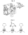
- FIG. 3 shows one example of the teaching in the case where one robot handles objects which are similar in configuration and are set on a plurality of jigs, respectively.
- a single robot handles objects set respectively on two or three jigs, and while the robots handles one object, another object is loaded on another jig; that is, loading and unloading an object and handling another object with the robot are carried out in a parallel mode, so that the idling time of the robot is eliminated to provide an effective or efficient work system.
- FIG. 4 is an explanatory diagram for a description of a robot interchangeability which is required in exchanging robots.
- a robot interchangeability function is required so that, immediately when a robot becomes out of order, it is replaced by another one and the new robot is operated with the same teaching data (as that of the old robot since the same control device is used).
- the robots are not always equal in mechanical dimension and the relative position of the jig and the robot is, in general, shifted during the robot exchanging operation, the robot interchangeability cannot be achieved merely by replacing the troubled robot.
- a robot #2 (FIG. 4) is replaced by an auxiliary robot, the locus (solid.
- the points P i , P 2 and P 3 of the object are the same points P 1 ', P 2 ' and P 3 ' of the same object, respectively, the data indicated by the dotted line become the data indicated by the solid line, because the points P 1 , P 2 and P 3 taught to the troubled robot are different from the points P 1 ', P 2 ' and P 3 taught to the auxiliary robot in the pulse values from the original points of the robot drive axes. Owing to this function, control of the relative position of the robot and the jig is unnecessary, and the troubled robot can be replaced by the auxiliary robot correctly.
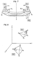
- FIG. 5 shows one example of the teaching according to the function in the case where a plurality of robots handle objects each of which has the same configuration.
- teaching is effected with one robot #l, and the data are stored in a cassette tape and are then inputted to the control devices of robots #2, #3, #4 and so on.
- the robots #2, #3, #4 and so on cannot be operated, because the robots are different in mechanical dimension or the relative positions of the robots and the jigs are different, which causes the working position of each robot to deviate.
- the position deviation of the robot #3 is as indicated by the broken lines, by way of example.
- FIG. 6 is an explanatory diagram for a description of the case where the above-described function is employed to amend data which have been taught when a work tool is deformed.
- the operator strikes the work tool against the jig or the like accidentally to deform the tool.
- job data are provided in correspondence to the number of kinds of products. If the deformed tool is operated according to the job data which have been stored in the control device, then the position of the tool is deviated as shown by the dotted line in FIG. 6. This difficulty may not be eliminated by repairing the deformed tool or by replacing it by a new one.
- FIG. 7 shows an example of a mirror image type shift, which is different from the three-dimensional rotation plus parallel movement shift as explained from FIG. 2 to FIG. 6.
- An object is not coincided with an object #b no matter how it is turned or moved in parallel, because the objects #a and #b are not congruent with each other and are symmetrical with each other with respect to a plane including a line Y-Y, as frequently found with symmetrical parts such as vehicle members.
- the object #a is turned and moved in parallel, then it comes to such position as shown by #b', and in this case the object (#b') is an mirror image of the object.#b.
- One object is first turned and moved in parallel so that it is in contact with and in symmetry with the other object with respect to a plane, and then the mirror image shift is effected in symmetry with the plane. Then, similarly as in the cases of FIGS. 2 through 6, the positional data of the object #b in work can be automatically provided merely by teaching the teaching data at #a and representative points P 1 , P 2 and P 3 of the object #a and the representative points P 1 ', P 2 f and P 3 ' of the object #b.
- the invention is intended to provide a locus shift control method in which, merely by teaching three representative points, teaching is simplified in handling objects similar in configuration with a robot, robots can be exchanged correctly, teaching can be simplified when a gun is deformed, and teaching can be simplified when a robot handles an object having parts which are symmetrical in mirror image manner.
- FIG. 8 is a model diagram extracting the points P 1 , P 2 , P 3 and P 4 , and the points P 1 ', P 2 ', P 3 ' and P 4 ' in FIG. 1.
- the problem in this case, is to obtain the coordinates of the points P 4 ' from the coordinates of the points P 1 , P 2 , P 3 , P 1 ', P 2 ', P 3 ' and P 4 .
- the coordinates of other points P 5 ', .... P n ', .... can be obtained by successively replacing the coordinates of the point P 4 with the coordinates of points P 5 , .... P n , ...
- ⁇ P 2 P 1 P 4 ⁇
- ⁇ P 2 P 1 P 4 ⁇
- ⁇ P 2 P 1 P 4 ⁇
- the direction cosine (l, m, n) of P 1 'P 2 ' and the direction cosine (h, i, j) of P 1 'P 3 ' can be readily obtained from the coordinates of the points P 1 ', P 2 ' and P 3 '.
- P 1 'P 4 ' L
- the coordinates X 4 ', Y 4 ', Z4 ' of the point P 4 ' can be obtained from the following expression (4): -
- the coordinates of the point P 4 1 is obtained according to P 1 P 4 ; however, it goes without saying that the coordinates may be obtained according to P 2 P 4 or P 3 P 4 .
- the average coordinates of the point P 4 ' may be obtained by averaging three different coordinates of the point P 4 ' which are obtained according to P 1 P 4 , P 2 P 4 and P 3 P 4 , res p ec- tively.
- a robot is controlled according to five axes ( ⁇ , ⁇ , ⁇ , y, T ), and therefore the teaching of the wrist is effected together with that of points P 1 , P 2' P 3' P 1 ', P 2 ' and P 3 '.
- the posture of the wrist is determined according to the content of work which should be done by the robot, and an object which is handled by the robot. For instance in the case of an arc welding robot, the posture of the wrist is controlled so that a welding torch angle and a welding torch advancing angle along the welding line of an object are maintained unchanged within the range suitable for the welding operation.
- the wrist posture for the object #a is different from that for the object #b. Accordingly, the wrist postures for the points P 4 ', P 5 ', ...., P' n ,, ... cannot be used for the points P 4 , P 5 ,...., P n , ...., as they are. For this reason, when the wrist bending axis (y: variable) and the wrist turning axis ( T : variable) take, as shown in Figs.
- the wrist posture of a robot in a new position #b can be amended by adding ⁇ and ⁇ to the wrist posture taught in a previous position #a.
- point P 4 ' ( ⁇ 4 ', ⁇ 4 ') can be obtained from the teaching data P 4 ( y 4 , T 4 ) by the following equation (6) thereby to effect correct amendments to the wrist posture.
- the data ⁇ and ⁇ can be obtained in various methods. For instance, a method may be employed in which AT and ⁇ are defined by the average value of the difference between the postures of the robot wrist axis respectively when the operation end of the robot are at the first and second representative points. Alternatively, a method may be employed in which ⁇ and ⁇ are defined by the difference between the wrist axis posture at the first representative point where the difference between the wrist axis postures respectively when the operation end of the robot is at the first representative point and the first work point, is minimum, and the wrist axis posture at the second representative point corresponding to the first representative point. The latter method is effective in the case where the wrist axis posture is greatly changed.
- FIG. 9 shows a model of an articulated robot.
- the swivel axis, the lower arm axis L and the upper arm axis l are controlled by rotation angles ⁇ , 0 and respectively.
- the wrist bending axis, and the wrist turning axis are controlled by rotation angles y and ⁇ , respectively.
- FIG. 10a is an external view showing the wrist of the articulated robot and a tool secured to the wrist.
- the point P which is at a distance A from the center Q of rotation of the wrist bending axis and at a distance ⁇ from the center of rotation of the wrist turning axis, is a control point to be taught. Therefore, the coordinates of the point P in the orthogonal coordinate system are as follows:
- the coordinates of the point P 4 '(X 4 ', Y 4 ', Z 4 ', ⁇ 4 ', ⁇ 4 ') on the articulated axis are defined by the following expression (8) which is obtained by subjecting the expression (7) to inverse transformation.
- the wrist axes are taught so that a torch coupled to the wrist holds angles (a torch angle and an advancing angle) necessary for welding with respect to the welding line of a workpiece.
- the angle between a surface defined by three representative points and a torch at each teaching point on the master job must be the same as those on the three-dimensionally shifted slave job, respectively.
- the wrist axes must be so controlled that the angle between a line connecting one of the three representative points to the work point and the axis of the torch connected to the wrist is maintained unchanged or substantially unchanged before and after three-dimensional locus shifting.
- P 1 ' designates one representative point on the slave job
- P 4 ' a work point
- A' an arbitrary point on the central axis of a welding torch connected to the robot wrist.
- P 1 , P 4 , A and n are employed instead of P 1 ', P 4 ', A' and ⁇ ', respectively.
- the angle H is intended to mean the angle between the center of rotation of a wrist turning axis and an axis line of a welding torch.
- the angle n at the point P 4 on the master job is represented in the form of the direction cosine (a, b, c) of P 4 A which is expressed by the following expression (9).
- a length M from a work point is defined on the central axis of a welding torch. It is assumed that the length M remains unchanged both on the master job and on the slave job.
- the coordinates (X A , Y A , Z A ) of a point A on the master job are:
- the point A is subjected to three-dimensional locus shifting according to three representative points. It is assumed that, after the three-dimensional locus shifting, the coordinates on the slave job designate a point A'.
- a', b' and c' can be readily obtained from the coordinates of the points P 4 ' and A'.
- FIGS. 10d and 10e These relationships are illustrated in FIGS. 10d and 10e.
- the wrist axis is controlled on the slave job so that its posture indicated by the dotted line in FIG. 10d is changed to one indicated by the solid line.
- FIG. 11 is a block diagram showing a locus shift controller comprising arithmetic units, and a microprocessor for controlling the operation of a robot, according to one embodiment of the invention.
- the microprocessor 111 When a status 1104 of the locus shift controller 110 is in a wait state and locus shift data are required, the microprocessor 111 reads the coordinates of the points P 1 , P 2 , P 3' P 1 ', P 2 ', P 3 ' and P 4 out of a memory (not shown) and sets them in registers "1".through “7” 1161 through 1167 (through data transfer 1105), and outputs a locus shift data forming macrocommand 1102.
- the locus shift controller 110 is made up of a sequence controller 1110, a microprogram memory 1120, a pipe line register 1130, a multiplexer 1140, an RALU (register and arithmetic logical unit) 1150 and the aforementioned registers "1" through "7" 1161 through 1167.
- the sequence controller 1110 is an address controller for controlling the execution sequence of microinstructions stored in the microprogram memory 1120.
- the sequence controller 1110 carries out various addressing operations and stack controls in response to control instructions from the pipe line register 1130. More specifically, the sequence controller 1110 deals with increment of an address being executed, address selection specified by a macrocommand 1102, jump address selection 1108 which is provided by the pipe line register 1130 in the case of a conditional jump according to the test condition 1107 of an RALU status 1106, a jump address section 1108 which is provided by the pipe line register 1130 in the case of a non-conditional jump, and stack control at the time of microsubroutine call.
- Input data for addressing are the macrocommand 1102, and an output 1108 of the pipe line register 1130.
- the sequence controller 1110 selects one of the two input data or selects none of the two input data to carry out the current address increment.
- Two locus shift data forming macrocommands namely, a rotation plus parallel movement command and a mirror image command are used.
- the commands are provided in such a manner as to indicate the top address of a locus shift data forming microprogram, in view of hardware.
- the microprogram memory 1120 is an essential element in the locus shift controller 110, and all arithmetic operations are carried out according to instructions from the microprogram memory 1120.
- the pipe line register 1130 is a buffer register for the microprogram memory 1120.
- the pipe line register 1130 applies an operating microinstruction to be executed at the present to the RALU 1150, applies a control instruction 1103 for determining the next microaddress to the sequence controller 1110 and the multiplexer 1140, and applies a jump address 1108 and a subroutine call address to the sequence controller 1110.
- a status 1104 signal for indicating "BUSY (locus shift. data are under preparation)" and "wait” is outputted to the microprocessor 111.
- the pipe line register 1130 forms two signal paths in such a manner that operations in the signal paths are carried out in a parallel mode, to reduce a micro cycle time, thereby to increase processing speed.
- One of the signal paths is of the control system, consisting of the pipe line register 1130, the sequence controller 1110 and the microprogram memory 1120, and the other is of the arithmetic system, consisting of the pipe line register 1130 and the RALU 1150.
- the pipe line register 1130 is provided to permit the operations in the two paths to be performed simultaneously in the same clock cycle.
- the multiplexer 1140 is to apply the test condition 1107 of the RALU status 1106 to the sequence controller 1110 according to the control instructions from the pipe line register 1130, to cause the sequence controller 1110 to execute the conditional jump.
- the RALU 1150 comprises a logic and arithmetic operation unit and a programmable register, and carries out operation instructions specified by the microprogram memory 1120.
- the operation result, i.e., the locus shift data P 4 ' is stored in the register "7" 1167.
- the registers "1" through “6" 1161 through 1166 store the coordinate data of the points P 1 , P 2 , P 3 , P 1 ', P 2 ' and P 3 '. Initially the coordinate data of P n , which is to be shifted, is set in the register "7" 1167. After the shift data has been formed, the coordinate data shifted, namely the data of P n ' is set in the register "7" 1167.
- the locus shift controller executes a wait routine and then the pipe line register 1130 . applies a wait status signal (1104) to the microprocessor 111.
- the sequence controller 1110 carries out address control so as to execute the wait routine, while receiving the control instructions 1103 for selecting the top address of the service microprogram from the pipe line register 1130.
- the microprocessor 111 sets the coordinates of P 1 (X 1 , Y 1 , Z 1 , ⁇ 1 , ⁇ 1 ), P 2 (X 2 , Y 2 , Z 2 , ⁇ 2 , ⁇ 2 ), P 3 (X 3 , Y 3 , Z 3 , ⁇ 3 , ⁇ 3 ), P 1 '(X 1 ', Y 1 ', Z 1 ', ⁇ 1 ', ⁇ 1 '), P 2 '(X 2 ', Y 2 ', Z 2 ', ⁇ 2 ', ⁇ 2 '), P 3 '(X 3 ', Y 3 ', Z 3 ', ⁇ 3 ', T 3 ') and the coordinates of data P 4 (X 4 , Y 4 , Z 4 , ⁇ 4 , ⁇ 4 ) to be shifted in the registers "1" through "7" 1161 through 1167, in the. case of a cartesian
- the microprocessor 111 When the microprocessor 111 outputs the locus shift data forming macrocommand 1102, the service program is executed, and the status 1104 becomes busy.
- the locus shift controller obtains the expression (1) from the expression (7) by using the coordinates set in the registers "1" through “7" 1161 through 1167.
- the data a, ⁇ , e, l, m, n, h, i and j are calculated, so that the direction cosines (a, b, c) are obtained according to the expression (2) in the case of the rotation plus parallel movement macrocommand, or according to the expression (3) in the case of the.mirror image command, and the coordinates X, Y, Z of the point P 4 ' are obtained from the expression (4).
- the wrist posture Y 4 ', ⁇ 4 ' is obtained by inserting the expressions (5) and P 4 ( ⁇ 4 , ⁇ 4 ) in the expression (6) or is obtained by the expressions (14).
- the value P 4 ' (X 4 ', Y 4 ', Z 4 ', ⁇ 4 ', ⁇ 4 ') is Set in the register "7" 1167, and the status signal 1104 comes to represent a waiting state as a result of which the locus shift controller 110 returns to a waiting routine.
- the data ⁇ 4 ', ⁇ 4 ' and ⁇ 4 ' obtained from the expression (8) and the data Y 4 ' and T 4 ' which have been obtained already are set in the register "7" 1167 and the locus shift controller 110 waits.
- the microprocessor 111 transfers the contents of the register "7" 1167 to the memory (not shown).
- the coordinate data P 5 to be newly shifted is set in the register "7" 1167, and similarly as in the above-described.operation the point P 5 ' is stored in the memory. This operation is carried out repeatedly until all the data are formed.
- FIG. 12 shows the relationships between the microprocessor and the axis motors which are controlled by commands from the microprocessor.
- positional deviation value, of each of axes at the present position of the operation point of the robot and at the point P 4 ' is, as the number of pulses, outputted at a specified speed from the command circuit 120.
- the difference between the number of axis command pulses and the number of pulses from the pulse generator is outputted by a difference counter.
- the motor is controlled so that the output of the difference counter is zeroed.
- the whole number of pulses between the present position and the point P 4 ' is outputted by a command circuit 120 and the output of the difference counter becomes zero, the motor is stopped. The same operations are carried out for all the axes simultaneously.
- the command circuit 120 operates to receive position pulse data from the microprocessor in FIG. 11 and to output them as axis command pulses uniformly in a period of time.
- the robot in the case where it is required to replace a robot, the robot must be replaced by another robot with high accuracy; however, according to the invention, in this case, it is unnecessary to strictly control the relative location of the robot, the jib and the object.
- production control can be achieved readily in the case where robots are used in a mass production line.
- the technical concept of the invention is applicable not only to the case where three representative points are given from an existing object by teaching, but also to the case where the X, Y and Z values of three points are given by a sensor such as a differential transformer.
- a differential transformer is used. to measure how much the three representative points of the object are shifted from the originally taught values, so that the X, Y and Z values thereof are utilized to correct the coordinate data of the representative points P 1 ', P 2 ' and P 3 ' thereby to convert the teaching data P 4 , P5 , .... , P n , ... into those P 4 ', P 5 ', ...., P n ', ... Therefore, even if the jigs are not uniform, the robots can be operated without additional teaching, and accordingly without stopping the line.
Abstract
Description
- This invention relates to industrial robots, and more particularly to a system of controlling the locus of an industrial robot.
- In the case of a conventional teaching playback robot, it is necessary to teach data to all of the parts of an object, even if a number of workpieces similar in configuration are included in the object or even when the robot handles the same objects set on a plurality of jigs.
- Furthermore, when a working tool is deformed accidentally, the shifted positions must be amended by changing the. data which have been taught to all the operating parts.
- Teaching data to the robot takes a lot of time and labor. Therefore, simplification of the teaching operation is practically essential in order to improve the operability of the robot..
- If, in the case where a number of robots are operated in a mass production line, any one of the robots becomes out of order, then it is necessary that the robot is replaced by an auxiliary robot immediately so that the production may not be stopped.
- In order to replace the robot, it is essential that the robots are interchangeable and that the relative position of the robot, the jib and the object to be handled by the robot must be strictly controlled and a mechanism for adjusting the relative position must be provided. However, these requirements involve various technical problems to be solved and it is unprofitable to satisfy all the requirements. Therefore, there has been a strong demand for the provision of an expensive method which ensures the interchanging of robots and simplifies the teaching operation.
- Accordingly, an object of this invention is to provide a locus control method for an industrial robot by which, in the case where the robot handles a number of objects similar in configuration, the teaching operation is simplified, when a robot becomes out of order it can be replaced by an auxiliary robot immediately, and when a working tool is deformed the shifted positions can be readily ammended.
- The foregoing object and other objects of the invention have been achieved by the provision of a robot locus control method in which, according to the invention, the coordinates of first three representative points and first work points of an object to be handled by a robot are. taught to the robot, when the relative position of the object and the robot is changed the coordinates of second three representative points corresponding to the first three representative points are taught to the robot, and the coordinates of second work points are calculated from the relative positions of the first three representative points and first work points and the second three representative points, to provide instructions for a robot working locus.
- The nature, principle and utility of the invention will become more apparent from the following detailed description when read in conjunction with the accompanying drawings.
- In the accompanying drawings:
- FIG. 1 is an explanatory diagram for a description of the principle of this invention;
- FIG. 2 is a perspective view showing an object having a number of congruent workpieces, for a description of one example of a teaching operation according to the invention;
- FIG. 3 is a perspective view showing one robot which handles a number of similar objects, for a description of another example of the teaching operation according to the invention;
- FIG. 4 is an explanatory diagram, for a description of a robot exchanging operation according to the invention;
- FIG. 5 is a perspective view showing a plurality of robots handling a plurality of similar objects, for a description of another example of the teaching operation according to the invention;
- FIG. 6 is an explanatory diagram for a description of the application of the invention to amendment of contents which have been taught when a working tool.is deformed;
- FIG. 7 is a diagram for a description of mirror image shifting;
- FIG. 8 is a model diagram showing various points on objects in FIG. 1;
- FIG. 9 is a model diagram showing an articulated robot;
- FIG. 10a is an external view showing the wrist of an articulated robot and a tool coupled to the wrist;
- FIGS. 10b through 10e are explanatory diagrams for a description of the two-axes control of the wrist;
- FIG. 11 is a block diagram showing a locus shift controller comprising arithmetic units, and a microprocessor for controlling the operation of a robot; and
- FIG. 12 is a block diagram showing the microprocessor and axis motors which are driven by command from the microprocessor.
- As conducive to a full understanding of this invention, first the principle of the invention will be described with reference to FIG. 1.
- Let us consider the case where an object or a workpiece, which is handled with a robot, is moved from a position #a to a position #b. When an object at the position #a is moved parallel and is then turned about an axis in space, then it will coincided with an object at the position #b.
- It is assumed that the three representative points P1, P2 and P3 (hereinafter referred to as "first representative points") of the object at the position #a and the work points (for instance welding lines) P4, P5, .... and Pn... (hereinafter referred to as "first work points") have been taught to the robot.
- The corresponding representative points P1', P2 1 and P3' (hereinafter referred to as "second representative points") of the object which is moved to the position #b are taught to the robot. The amount of shift in three-dimensional rotation plus parallel movement from a surface defined by the points P1, P2 and P3 to a surface defined by the points P1', P2' and P3 is obtained, so that the positional data of new work points P4', P5', ... and Pn' .. (hereinafter referred to as "second work points") are automatically obtained by carrying out the calculation which is equivalent to the translation of the relationship between the work points P4, P5, ... and Pn... and the surface defined by the points P1, P2 and P3 to the surface defined by the points P1', P2' and P3'.
- In other words, merely by teaching the three representative points P1', P2' and P3', the positional data of all the work points P4', P5', ..... and Pn'... of the object at the position #b are automatically provided. Thus, the efficiency of teaching operation is greatly improved.
- FIG. 2 shows one example of the teaching in which the above-described technical concept is applied to an object in which a number of similar workpieces are arranged. In this case, merely by teaching the welding lines and representative points P1, P2 and P3 of a workpiece W1, the representative points P1', P2' and P3' of a workpiece W2, the representative points Pl", P2" and P3" of a workpiece W3 and so forth, the positional data of the welding lines of the workpieces W2, W3 and so forth are automatically provided.
- FIG. 3 shows one example of the teaching in the case where one robot handles objects which are similar in configuration and are set on a plurality of jigs, respectively. In general, in the case of an industrial robot, a single robot handles objects set respectively on two or three jigs, and while the robots handles one object, another object is loaded on another jig; that is, loading and unloading an object and handling another object with the robot are carried out in a parallel mode, so that the idling time of the robot is eliminated to provide an effective or efficient work system. In this case also, merely by teaching the robot an object on one jig and also only the representative points P1, P2, P3, P1', P2', P3', P1', P2", P3" and so on, all the positional data of the other objects on the other jigs are automatically provided.
- FIG. 4 is an explanatory diagram for a description of a robot interchangeability which is required in exchanging robots. In the case where a plurality of robots are operated in a large scale production line, a robot interchangeability function is required so that, immediately when a robot becomes out of order, it is replaced by another one and the new robot is operated with the same teaching data (as that of the old robot since the same control device is used). However, since the robots are not always equal in mechanical dimension and the relative position of the jig and the robot is, in general, shifted during the robot exchanging operation, the robot interchangeability cannot be achieved merely by replacing the troubled robot. When a robot #2 (FIG. 4) is replaced by an auxiliary robot, the locus (solid. line) of the
robot # 2, which was drawn before it became out of order, is shifted as indicated by the dotted line. The representative points P1, P2 and P3 on the locus (solid line) have been taught to the robot and stored in a memory in the control device. Under this condition, only three representative points P1', P2' and P3' of the object are taught to the auxiliary robot. Then, all the positional data indicated by the dotted line are automatically amended to the positional data indicated by the solid line by means of the calculation of three dimensional parallel and rotational shift by use of the first representative points and the second representative points. Thus, the robot has been replaced by the auxiliary robot correctly. - Although the points Pi, P2 and P3 of the object are the same points P1', P2' and P3' of the same object, respectively, the data indicated by the dotted line become the data indicated by the solid line, because the points P1, P2 and P3 taught to the troubled robot are different from the points P1', P2' and P3 taught to the auxiliary robot in the pulse values from the original points of the robot drive axes. Owing to this function, control of the relative position of the robot and the jig is unnecessary, and the troubled robot can be replaced by the auxiliary robot correctly.
- FIG. 5 shows one example of the teaching according to the function in the case where a plurality of robots handle objects each of which has the same configuration. In this case, teaching is effected with one robot #l, and the data are stored in a cassette tape and are then inputted to the control devices of
robots # 2, #3, #4 and so on. With the data thus inputted, therobots # 2, #3, #4 and so on cannot be operated, because the robots are different in mechanical dimension or the relative positions of the robots and the jigs are different, which causes the working position of each robot to deviate. The position deviation of therobot # 3 is as indicated by the broken lines, by way of example. In this case, all the position deviations can be automatically amended merely by teaching the representative points P1', P2', P3', P1", P2", P3" and so on of therobots # 2, #3 and so on according to the above-described function. - FIG. 6 is an explanatory diagram for a description of the case where the above-described function is employed to amend data which have been taught when a work tool is deformed. In teaching, sometimes the operator strikes the work tool against the jig or the like accidentally to deform the tool. In general, in the case where various products are manufactured on small scale by one robot, job data are provided in correspondence to the number of kinds of products. If the deformed tool is operated according to the job data which have been stored in the control device, then the position of the tool is deviated as shown by the dotted line in FIG. 6. This difficulty may not be eliminated by repairing the deformed tool or by replacing it by a new one. However, since tools are, in general, not interchangeable, the amount of positional deviation cannot be completely eliminated, although it may be reduced. In such a case, the above-described function is effective. Automatic amendment to job data including no positional deviation can be achieved merely by teaching the representative points P1', P2' and P 3'.
- FIG. 7 shows an example of a mirror image type shift, which is different from the three-dimensional rotation plus parallel movement shift as explained from FIG. 2 to FIG. 6. An object is not coincided with an object #b no matter how it is turned or moved in parallel, because the objects #a and #b are not congruent with each other and are symmetrical with each other with respect to a plane including a line Y-Y, as frequently found with symmetrical parts such as vehicle members. When the object #a is turned and moved in parallel, then it comes to such position as shown by #b', and in this case the object (#b') is an mirror image of the object.#b. One object is first turned and moved in parallel so that it is in contact with and in symmetry with the other object with respect to a plane, and then the mirror image shift is effected in symmetry with the plane. Then, similarly as in the cases of FIGS. 2 through 6, the positional data of the object #b in work can be automatically provided merely by teaching the teaching data at #a and representative points P1, P2 and P3 of the object #a and the representative points P1', P2 f and P3' of the object #b.
- As was described above, the invention is intended to provide a locus shift control method in which, merely by teaching three representative points, teaching is simplified in handling objects similar in configuration with a robot, robots can be exchanged correctly, teaching can be simplified when a gun is deformed, and teaching can be simplified when a robot handles an object having parts which are symmetrical in mirror image manner.
- The invention will be described in more detail.
- FIG. 8 is a model diagram extracting the points P1, P2, P3 and P4, and the points P1', P2', P3' and P4' in FIG. 1. The problem, in this case, is to obtain the coordinates of the points P4' from the coordinates of the points P1, P2, P3, P1', P2', P3' and P4. Similarly, the coordinates of other points P5', .... Pn', .... can be obtained by successively replacing the coordinates of the point P4 with the coordinates of points P5, .... Pn, ...
- The coordinates of the taught points P1, P2, P3, P1', P2', P3' and P4 are as follows:

- <P2P1P4 = α, <P2P1P4 = β and <P2P1P3 = ε are internal angles of ΔP2P1P4, ΔP3P1P4 and ΔP2P1P3, respectively, and can be readily obtained from the coordinates of the points P1, P2, P3 and P4.
- As the same object is merely moved, these angles remain unchanged. Therefore <P2'P1'P4' = α, <P3'P1'P4' = β and <P2'P1'P3' = ε.
- The direction cosine (ℓ, m, n) of
P 1 'P 2 ' and the direction cosine (h, i, j) ofP 1 'P 3 ' can be readily obtained from the coordinates of the points P1', P2' and P3'. - Accordingly, the direction cosine (a, b, c) of
P 1 'P 4 ' is defined by the following expression (2):
- In the case of mirror image, the direction cosine (a, b, c) is defined by the following expression (3):

-
P 1 P 4 (= L) is obtained from the coordinates of the points P1 and P4. AsP 1 'P 4 ' = L, the coordinates X4', Y4', Z4' of the point P4' can be obtained from the following expression (4): -
- In the expression (4), the coordinates of the point P4 1 is obtained according to
P 1 P 4 ; however, it goes without saying that the coordinates may be obtained according to P2P4 or P3P4. Furthermore, the average coordinates of the point P4' may be obtained by averaging three different coordinates of the point P4' which are obtained according toP 1 P 4 ,P 2 P 4 andP 3 P 4 , respec- tively. As is shown in Fig. 9, a robot is controlled according to five axes (ψ, θ, ϕ, y, T), and therefore the teaching of the wrist is effected together with that of points P1, P 2' P 3' P1', P 2' and P3'. - In general, the posture of the wrist is determined according to the content of work which should be done by the robot, and an object which is handled by the robot. For instance in the case of an arc welding robot, the posture of the wrist is controlled so that a welding torch angle and a welding torch advancing angle along the welding line of an object are maintained unchanged within the range suitable for the welding operation.
- Since the objects #a and #b are at different positions, the wrist posture for the object #a is different from that for the object #b. Accordingly, the wrist postures for the points P4', P5', ...., P'n,, ... cannot be used for the points P4, P5,...., Pn, ...., as they are. For this reason, when the wrist bending axis (y: variable) and the wrist turning axis (T: variable) take, as shown in Figs. 9 and 10, positions represented by the following points P1(γ1, τ1), P2(γ2, τ2), P3(γ3, τ3) P1'(γ1', τ1'), P2'(γ2',τ2') and P3'(γ3', τ3'), Δγ and Δτ are calculated by the following equations (5)

- Thus, the wrist posture of a robot in a new position #b can be amended by adding Δγ and Δτ to the wrist posture taught in a previous position #a. Namely, point P4' (γ4', τ4') can be obtained from the teaching data P4 (y 4, T4) by the following equation (6) thereby to effect correct amendments to the wrist posture.

- The data Δτ and Δγ can be obtained in various methods. For instance, a method may be employed in which AT and Δγ are defined by the average value of the difference between the postures of the robot wrist axis respectively when the operation end of the robot are at the first and second representative points. Alternatively, a method may be employed in which Δτ and Δγ are defined by the difference between the wrist axis posture at the first representative point where the difference between the wrist axis postures respectively when the operation end of the robot is at the first representative point and the first work point, is minimum, and the wrist axis posture at the second representative point corresponding to the first representative point. The latter method is effective in the case where the wrist axis posture is greatly changed.
- In the case of a cartesian coordinates robot, the coordinates of the points, P1, P2, P3, P4, P1', P 2 1 and P3' are stored in terms of X, Y, Z, and therefore P 4' (X4', Y 4', Z4', γ4', τ4') can be obtained from the expressions (1) through (6). In the case of an articulated robot, a cylindrical coordinates robot or a polar coordinates robot, the taught data of the drive axes must be subjected to orthogonal coordinate transformation to obtain the expression (1). The data X4', Y4', Z4' except the data γ4', τ4' of the wrist are required to inversely transform their coordinates into those which are proper to each of three drive axis of the robot.
- FIG. 9 shows a model of an articulated robot. The swivel axis, the lower arm axis L and the upper arm axis ℓ are controlled by rotation angles ϕ, 0 and respectively. The wrist bending axis, and the wrist turning axis are controlled by rotation angles y and τ, respectively.
- FIG. 10a is an external view showing the wrist of the articulated robot and a tool secured to the wrist.
- The point P, which is at a distance A from the center Q of rotation of the wrist bending axis and at a distance δ from the center of rotation of the wrist turning axis, is a control point to be taught. Therefore, the coordinates of the point P in the orthogonal coordinate system are as follows:

- As the data γ4', T4' of the wrist axis have-been defined according to the expression (6), the coordinates of the point P4'(X4', Y 4', Z4', γ4', τ4') on the articulated axis are defined by the following expression (8) which is obtained by subjecting the expression (7) to inverse transformation.

- In general, in a robot teaching operation, not only teaching of points to be taught but also teaching of the posture of a tool connected to the robot wrists with respect to a workpiece are essential.
- In the case of a welding robot, the wrist axes are taught so that a torch coupled to the wrist holds angles (a torch angle and an advancing angle) necessary for welding with respect to the welding line of a workpiece.
- If the posture of the torch with respect to the welding line at each of teaching points, which is taught in a master job, is the same as the posture with respect to the welding line at each of the corresponding points in a slave job which is three-dimensionally shifted, then a posture necessary for work can be obtained.
- For this purpose, the angle between a surface defined by three representative points and a torch at each teaching point on the master job must be the same as those on the three-dimensionally shifted slave job, respectively.
- In practice, the wrist axes must be so controlled that the angle between a line connecting one of the three representative points to the work point and the axis of the torch connected to the wrist is maintained unchanged or substantially unchanged before and after three-dimensional locus shifting.
- In FIG. lOb, P1' designates one representative point on the slave job; P4', a work point; and A', an arbitrary point on the central axis of a welding torch connected to the robot wrist.
- In this case, an angle µ' between segments
P 1 'P 4 ' and A'P4' should be controlled. - On the master job, P1, P4, A and n are employed instead of P1', P4', A' and η', respectively. The two wrist.axes are controlled so that η' = n.
- In this case, it is necessary to define an angle H. The angle H is intended to mean the angle between the center of rotation of a wrist turning axis and an axis line of a welding torch. The angle n at the point P4 on the master job is represented in the form of the direction cosine (a, b, c) of
P4A which is expressed by the following expression (9).
- Now, as shown in FIG. 10b and FIG. 10c, a length M from a work point is defined on the central axis of a welding torch. It is assumed that the length M remains unchanged both on the master job and on the slave job.
- The coordinates (XA, YA, ZA) of a point A on the master job are:

- - The point A is subjected to three-dimensional locus shifting according to three representative points. It is assumed that, after the three-dimensional locus shifting, the coordinates on the slave job designate a point A'.
- From the coordinates (X4', Y4', Z4') of the point P4', the direction ψ4' of an arm is:

- Thus, the direction cosines (a', b', c') of
P4'A' are:
- Also, a', b' and c' can be readily obtained from the coordinates of the points P4' and A'.

- From the expressions (12) and (13), γ4' and τ4' are:

- These relationships are illustrated in FIGS. 10d and 10e. As is apparent from the above description, the wrist axis is controlled on the slave job so that its posture indicated by the dotted line in FIG. 10d is changed to one indicated by the solid line.
- FIG. 11 is a block diagram showing a locus shift controller comprising arithmetic units, and a microprocessor for controlling the operation of a robot, according to one embodiment of the invention.
- When a status 1104 of the locus shift controller 110 is in a wait state and locus shift data are required, the microprocessor 111 reads the coordinates of the points P1, P2, P3' P1', P2', P3' and P4 out of a memory (not shown) and sets them in registers "1".through "7" 1161 through 1167 (through data transfer 1105), and outputs a locus shift
data forming macrocommand 1102. - The locus shift controller 110 is made up of a
sequence controller 1110, amicroprogram memory 1120, apipe line register 1130, amultiplexer 1140, an RALU (register and arithmetic logical unit) 1150 and the aforementioned registers "1" through "7" 1161 through 1167. - The
sequence controller 1110 is an address controller for controlling the execution sequence of microinstructions stored in themicroprogram memory 1120. Thesequence controller 1110 carries out various addressing operations and stack controls in response to control instructions from thepipe line register 1130. More specifically, thesequence controller 1110 deals with increment of an address being executed, address selection specified by amacrocommand 1102, jumpaddress selection 1108 which is provided by thepipe line register 1130 in the case of a conditional jump according to thetest condition 1107 of anRALU status 1106, ajump address section 1108 which is provided by thepipe line register 1130 in the case of a non-conditional jump, and stack control at the time of microsubroutine call. - Input data for addressing are the
macrocommand 1102, and anoutput 1108 of thepipe line register 1130. - Depending on the microprogram, i.e., the
control instruction 1103 from thepipe line register 1130, it is determined whether thesequence controller 1110 selects one of the two input data or selects none of the two input data to carry out the current address increment. Two locus shift data forming macrocommands, namely, a rotation plus parallel movement command and a mirror image command are used. - The commands are provided in such a manner as to indicate the top address of a locus shift data forming microprogram, in view of hardware.
- The
microprogram memory 1120 is an essential element in the locus shift controller 110, and all arithmetic operations are carried out according to instructions from themicroprogram memory 1120. - The
pipe line register 1130 is a buffer register for themicroprogram memory 1120. Thepipe line register 1130 applies an operating microinstruction to be executed at the present to theRALU 1150, applies acontrol instruction 1103 for determining the next microaddress to thesequence controller 1110 and themultiplexer 1140, and applies ajump address 1108 and a subroutine call address to thesequence controller 1110. Also, a status 1104 signal for indicating "BUSY (locus shift. data are under preparation)" and "wait" is outputted to the microprocessor 111. - The
pipe line register 1130 forms two signal paths in such a manner that operations in the signal paths are carried out in a parallel mode, to reduce a micro cycle time, thereby to increase processing speed. - One of the signal paths is of the control system, consisting of the
pipe line register 1130, thesequence controller 1110 and themicroprogram memory 1120, and the other is of the arithmetic system, consisting of thepipe line register 1130 and theRALU 1150. Thepipe line register 1130 is provided to permit the operations in the two paths to be performed simultaneously in the same clock cycle. - At the rise of a
clock CP 1101, the next instruction of the microprogram prepared in the path of the control system is applied to the input of thepipe line register 1130. Therefore, a high speed operation, in which the memory fetch time is substantially zero, can be carried out. - The
multiplexer 1140 is to apply thetest condition 1107 of theRALU status 1106 to thesequence controller 1110 according to the control instructions from thepipe line register 1130, to cause thesequence controller 1110 to execute the conditional jump. - The
RALU 1150 comprises a logic and arithmetic operation unit and a programmable register, and carries out operation instructions specified by themicroprogram memory 1120. The operation result, i.e., the locus shift data P4' is stored in the register "7" 1167. - The registers "1" through "6" 1161 through 1166 store the coordinate data of the points P1, P2, P3, P1', P2' and P3'. Initially the coordinate data of Pn, which is to be shifted, is set in the register "7" 1167. After the shift data has been formed, the coordinate data shifted, namely the data of Pn' is set in the register "7" 1167.
- Formation of the locus shift data will be described with reference to FIG. 11.
- Initially, the locus shift controller executes a wait routine and then the
pipe line register 1130. applies a wait status signal (1104) to the microprocessor 111. Upon reception of the locus shiftdata forming macrocommand 1102, thesequence controller 1110 carries out address control so as to execute the wait routine, while receiving thecontrol instructions 1103 for selecting the top address of the service microprogram from thepipe line register 1130. - Before starting the locus shift, the microprocessor 111 sets the coordinates of P1(X1, Y1, Z1, γ1, τ1), P2(X2, Y2, Z2, γ2, τ2), P3(X3, Y3, Z3, γ3, τ3), P1'(X1', Y1', Z1', γ1', τ1'), P2'(X2', Y2', Z2', γ2', τ2'), P3'(X3', Y 3', Z3', γ3', T3') and the coordinates of data P4(X4, Y4, Z4, γ4, τ4) to be shifted in the registers "1" through "7" 1161 through 1167, in the. case of a cartesian coordinates robot.
- For instance in the case of an articulated robot, the coordinates of P1(ψ1, θ1, ϕ1, γ1, τ1), P2(ψ2, θ2, ϕ2, γ2, T2) and so forth are set in the registers "1" through "7".
- When the microprocessor 111 outputs the locus shift
data forming macrocommand 1102, the service program is executed, and the status 1104 becomes busy. - In the case of the articulated robot, the locus shift controller obtains the expression (1) from the expression (7) by using the coordinates set in the registers "1" through "7" 1161 through 1167.
- In the case of the cartesian coordinates robot, the expression (1) is given by the registers "1" through "7" 1161 through 1167.
- The data a, β, e, ℓ, m, n, h, i and j are calculated, so that the direction cosines (a, b, c) are obtained according to the expression (2) in the case of the rotation plus parallel movement macrocommand, or according to the expression (3) in the case of the.mirror image command, and the coordinates X, Y, Z of the point P4' are obtained from the expression (4). The wrist posture Y4', τ4' is obtained by inserting the expressions (5) and P4(γ4, τ4) in the expression (6) or is obtained by the expressions (14).
- In the case of the cartesian robot, the value P4' (X4', Y4', Z4', γ4', τ4') is Set in the register "7" 1167, and the status signal 1104 comes to represent a waiting state as a result of which the locus shift controller 110 returns to a waiting routine.
- In the case of the articulated robot, the data φ4', θ4' and ϕ4' obtained from the expression (8) and the data Y4' and T4' which have been obtained already are set in the register "7" 1167 and the locus shift controller 110 waits.
- When the status signal 1104 is changed from "busy" to "wait", the microprocessor 111 transfers the contents of the register "7" 1167 to the memory (not shown).
- Next, the coordinate data P5 to be newly shifted is set in the register "7" 1167, and similarly as in the above-described.operation the point P5' is stored in the memory. This operation is carried out repeatedly until all the data are formed.
- FIG. 12 shows the relationships between the microprocessor and the axis motors which are controlled by commands from the microprocessor. During the playback, positional deviation value, of each of axes at the present position of the operation point of the robot and at the point P4' is, as the number of pulses, outputted at a specified speed from the
command circuit 120. - The difference between the number of axis command pulses and the number of pulses from the pulse generator is outputted by a difference counter. The motor is controlled so that the output of the difference counter is zeroed. When the whole number of pulses between the present position and the point P4' is outputted by a
command circuit 120 and the output of the difference counter becomes zero, the motor is stopped. The same operations are carried out for all the axes simultaneously. - The
command circuit 120 operates to receive position pulse data from the microprocessor in FIG. 11 and to output them as axis command pulses uniformly in a period of time. - As is apparent from the above description, according to the invention, in general robots including articulated robots, cylindrical coordinates robots, polar coordinates robots, etc., the three-dimensional rotation plus parallel movement shift and mirror image shift of locus data including suitable wrist axis correction are achieved merely by correctly teaching three representative points.
- Heretofore, it is required for the operator to teach all the points, when the robot handles objects similar in configuration or mirror image objects. However, this troublesome operation can be eliminated according to the invention. That is, all the coordinate data are automatically formed merely by teaching only one object and representative points. Thus, the teaching operation is greatly simplified. In addition, in the case where
- the tool is deformed, the teaching can be readily amended.
- Furthermore, in the case where it is required to replace a robot, the robot must be replaced by another robot with high accuracy; however, according to the invention, in this case, it is unnecessary to strictly control the relative location of the robot, the jib and the object. Thus, production control can be achieved readily in the case where robots are used in a mass production line.
- The above description is explained with the case where the coordinate data of first work points and first three representative points of an object are taught by the teaching operation. However, the invention is also . useful to the case where, these coordinate data are given in form of the numerical values which are numelized by use of a drawing of an object or any digitizer, and all the coordinate data of second work points are automatically formed through the above described method by use of these numerical coordinate data and second three representative points which are taught by the teaching operation.
- The technical concept of the invention is applicable not only to the case where three representative points are given from an existing object by teaching, but also to the case where the X, Y and Z values of three points are given by a sensor such as a differential transformer.
- In the case where, although the accuracy of an object is guaranteed, it is difficult to improve the accuracy because the object is large and accordingly a jib for receiving is intricated as in the case of a vehicle's chassis, a differential transformer is used. to measure how much the three representative points of the object are shifted from the originally taught values, so that the X, Y and Z values thereof are utilized to correct the coordinate data of the representative points P1', P2' and P3' thereby to convert the teaching data P4, P5, ...., Pn, ... into those P4', P5', ...., Pn', ... Therefore, even if the jigs are not uniform, the robots can be operated without additional teaching, and accordingly without stopping the line.
Claims (5)
coordinates of second work points are calculated from relative positions of said first three representative points and first work points and said second three representative points, to provide commands for a robot working locus, and
said robot working locus is controlled according to said commands.
characterized in that
correcting values Δγ and Δτ are added to a posture of a wrist axes at said first work points,thereby to obtain a posture of said wrist axes at said second work points.
characterized in that
said wrist axis is controlled on a slave job so that an angle between the axis of a torch and a line connecting one representative point to a work point in a slave job is substantially equal to an angle between the axis of said torch and a line connecting. one corresponding representative point to a corresponding work point in a master job.
characterized by
characterized in that
coordinate data of first work points and first three representative points of an object to be handled by a robot are given in form of numerical values to said robot so that, when the robot trajectory based on the numerical coordinate data of the first work points deviates from the actual work lines of an object, coordinates of second three representative points corresponding to said first representative points of said object may be taught, coordinates of second work points are properly calculated from relative positions of said first three representative points and first work points and said second three representative points, to provide commands for a robot working locus, and said robot working locus is controlled according to said commands.
Applications Claiming Priority (2)
| Application Number | Priority Date | Filing Date | Title |
|---|---|---|---|
| JP56044275A JPH065486B2 (en) | 1981-03-26 | 1981-03-26 | Robot trajectory control method |
| JP44275/81 | 1981-03-26 |
Publications (2)
| Publication Number | Publication Date |
|---|---|
| EP0062244A1 true EP0062244A1 (en) | 1982-10-13 |
| EP0062244B1 EP0062244B1 (en) | 1989-09-06 |
Family
ID=12686952
Family Applications (1)
| Application Number | Title | Priority Date | Filing Date |
|---|---|---|---|
| EP82102483A Expired EP0062244B1 (en) | 1981-03-26 | 1982-03-25 | Robot locus control system |
Country Status (4)
| Country | Link |
|---|---|
| US (1) | US4495588A (en) |
| EP (1) | EP0062244B1 (en) |
| JP (1) | JPH065486B2 (en) |
| DE (1) | DE3279928D1 (en) |
Cited By (10)
| Publication number | Priority date | Publication date | Assignee | Title |
|---|---|---|---|---|
| EP0104270A1 (en) * | 1982-09-23 | 1984-04-04 | Kabushiki Kaisha Sankyo Seiki Seisakusho | Robot control apparatus |
| DE3246828A1 (en) * | 1982-12-17 | 1984-06-20 | Fraunhofer-Gesellschaft zur Förderung der angewandten Forschung e.V., 8000 München | Mobile transporting and handling device |
| EP0114362A1 (en) * | 1982-12-22 | 1984-08-01 | Hitachi, Ltd. | Method and system for controlling industrial robot |
| EP0172257A1 (en) * | 1984-02-20 | 1986-02-26 | Fanuc Ltd. | Scaling method in an automatic welding machine |
| DE3731704A1 (en) * | 1986-09-29 | 1988-03-31 | Asea Ab | METHOD AND ARRANGEMENT FOR CALIBRATING A SENSOR MOUNTED ON THE HAND OF AN INDUSTRIAL ROBOT |
| EP0361663A2 (en) * | 1988-09-26 | 1990-04-04 | Ford Motor Company Limited | Method and system for a robot path |
| US5053976A (en) * | 1989-05-22 | 1991-10-01 | Honda Giken Kogyo Kabushiki Kaisha | Method of teaching a robot |
| US5769954A (en) * | 1993-08-13 | 1998-06-23 | Putzmeister Aktiengesellschaft | Process and device for treating the surface of large objects |
| US5833762A (en) * | 1993-08-13 | 1998-11-10 | Fraunhofer-Gesellschaft Zur Foerderung Der Angewandten Forschung E.V. | Process for treating an object, in particular an airplane |
| EP1727008A2 (en) | 2005-05-27 | 2006-11-29 | Fanuc Ltd | Device and method for correcting taught points in a robot program |
Families Citing this family (60)
| Publication number | Priority date | Publication date | Assignee | Title |
|---|---|---|---|---|
| US4577284A (en) * | 1982-03-31 | 1986-03-18 | International Business Machines Corporation | Adaptive robot batch assembly system |
| JPH0677210B2 (en) * | 1983-03-22 | 1994-09-28 | 川崎重工業株式会社 | Industrial robot having teaching data conversion function |
| JPS59180605A (en) * | 1983-03-31 | 1984-10-13 | Hitachi Ltd | Device for converting working data of robot |
| US4670849A (en) * | 1983-03-31 | 1987-06-02 | Hitachi, Ltd. | Position error correcting method and apparatus for industrial robot |
| JPS59189415A (en) * | 1983-04-13 | 1984-10-27 | Hitachi Ltd | Method and device for teaching motion of industrial robot |
| SE8304101L (en) * | 1983-07-22 | 1985-01-23 | Ibm Svenska Ab | SYSTEM FOR AUTOMATIC CALIBRATION OF SPACE COORDINATES BY A ROBOT GRIPPER IN SEX FREEDOM |
| GB8319892D0 (en) * | 1983-07-23 | 1983-08-24 | Ae Plc | Machine tool control |
| GB2146796B (en) * | 1983-08-31 | 1986-12-17 | Mitsubishi Electric Corp | Method for controlling an industrial robot to perform weaving-like motion and apparatus for practising the same |
| JPS6054011A (en) * | 1983-09-03 | 1985-03-28 | Fanuc Ltd | Position control method of industrial robot |
| JPS6065304A (en) * | 1983-09-20 | 1985-04-15 | Toyota Motor Corp | Teaching point correcting method of robot |
| JPS6095605A (en) * | 1983-10-31 | 1985-05-29 | Nissan Motor Co Ltd | Teaching data correcting method of robot |
| JPS60107107A (en) * | 1983-11-16 | 1985-06-12 | Nachi Fujikoshi Corp | Off-line teaching method of industrial robot |
| JPH0727408B2 (en) * | 1984-01-19 | 1995-03-29 | 株式会社日立製作所 | Robot handling device with fixed 3D vision |
| JPS60175112A (en) * | 1984-02-20 | 1985-09-09 | Dainichi Kiko Kk | Working method on conveyer by industrial robot |
| DE3417868C2 (en) * | 1984-05-14 | 1986-08-07 | Deutsche Forschungs- und Versuchsanstalt für Luft- und Raumfahrt e.V., 5000 Köln | Method for controlling robot movements |
| JP2701022B2 (en) * | 1984-05-22 | 1998-01-21 | ファナック 株式会社 | Numerical controller with programmable mirror image function |
| JPS617904A (en) * | 1984-06-22 | 1986-01-14 | Seiko Instr & Electronics Ltd | Robot controlling system |
| JPS6125207A (en) * | 1984-07-12 | 1986-02-04 | Fanuc Ltd | Setting system of tool coordinate system |
| JPS6126111A (en) * | 1984-07-16 | 1986-02-05 | Shin Meiwa Ind Co Ltd | Industrial robot |
| JPS6132113A (en) * | 1984-07-23 | 1986-02-14 | Seiko Instr & Electronics Ltd | Robot control system |
| JPS6142004A (en) * | 1984-08-06 | 1986-02-28 | Toyota Central Res & Dev Lab Inc | Following-up robot device |
| JPH0754445B2 (en) * | 1984-08-10 | 1995-06-07 | 株式会社日立製作所 | Robot geometric error correction method |
| JPH06105413B2 (en) * | 1984-09-19 | 1994-12-21 | 川崎重工業株式会社 | Teaching method for industrial robot |
| JPS61109109A (en) * | 1984-10-31 | 1986-05-27 | Sankyo Seiki Mfg Co Ltd | Positioning method for planar multi-joint type robot |
| JPS61136106A (en) * | 1984-12-07 | 1986-06-24 | Fanuc Ltd | Information method of cubic arc |
| JPS61145612A (en) * | 1984-12-18 | 1986-07-03 | Toshiba Mach Co Ltd | Coordinate system setting method for robot teaching |
| JP2684359B2 (en) * | 1985-02-22 | 1997-12-03 | ファナック 株式会社 | Robot work Cartesian coordinate system setting device |
| US4817017A (en) * | 1985-04-08 | 1989-03-28 | Mitsubishi Denki Kabushiki Kaisha | Industrial robot |
| US4998206A (en) * | 1988-07-29 | 1991-03-05 | The Boeing Company | Automated method and apparatus for fabricating sheet metal parts and the like using multiple manufacturing stations |
| US4700308A (en) * | 1985-04-24 | 1987-10-13 | The Boeing Company | Method of fabricating sheet metal parts and the like |
| DE3613945A1 (en) * | 1985-04-26 | 1986-10-30 | Mazda Motor Corp., Hiroshima | VARIABLE VALVE MECHANISM FOR COMBUSTION ENGINES |
| US4690110A (en) * | 1985-04-26 | 1987-09-01 | Mazda Motor Corporation | Variable valve mechanism for internal combustion engines |
| US4639878A (en) * | 1985-06-04 | 1987-01-27 | Gmf Robotics Corporation | Method and system for automatically determining the position and attitude of an object |
| JPS61281305A (en) * | 1985-06-06 | 1986-12-11 | Toyota Motor Corp | Articulated robot control device |
| JPS6258307A (en) * | 1985-09-09 | 1987-03-14 | Aida Eng Ltd | Synchronous control system for plural robots |
| JPH0789287B2 (en) * | 1985-11-07 | 1995-09-27 | 三菱電機株式会社 | Robot programming method |
| US5117348A (en) * | 1986-03-28 | 1992-05-26 | The Ingersoll Milling Machine Company | Method for alignment of a representative surface to an actual surface for a tape laying machine |
| US4835710A (en) * | 1987-07-17 | 1989-05-30 | Cincinnati Milacron Inc. | Method of moving and orienting a tool along a curved path |
| JP2511072B2 (en) * | 1987-10-23 | 1996-06-26 | 三菱重工業株式会社 | Recording / playback method of teaching data in robot |
| JP2759324B2 (en) * | 1988-04-23 | 1998-05-28 | ファナック株式会社 | Robot mirror image method |
| JPH079606B2 (en) * | 1988-09-19 | 1995-02-01 | 豊田工機株式会社 | Robot controller |
| JP2913661B2 (en) * | 1989-04-12 | 1999-06-28 | 株式会社安川電機 | Robot control method |
| EP0433460A1 (en) * | 1989-06-07 | 1991-06-26 | Fanuc Ltd. | Nc data edition |
| US6535794B1 (en) | 1993-02-23 | 2003-03-18 | Faro Technologoies Inc. | Method of generating an error map for calibration of a robot or multi-axis machining center |
| US5889924A (en) * | 1994-03-23 | 1999-03-30 | Kabushiki Kaisha Yaskawa Denki | Industrial robots controller |
| US5495410A (en) * | 1994-08-12 | 1996-02-27 | Minnesota Mining And Manufacturing Company | Lead-through robot programming system |
| US5969973A (en) * | 1994-11-09 | 1999-10-19 | Amada Company, Ltd. | Intelligent system for generating and executing a sheet metal bending plan |
| US5835684A (en) | 1994-11-09 | 1998-11-10 | Amada Company, Ltd. | Method for planning/controlling robot motion |
| WO1996014968A1 (en) * | 1994-11-09 | 1996-05-23 | Amada Company, Limited | Shear force sensing system |
| DE69534977T2 (en) | 1994-11-09 | 2007-06-06 | Amada Co., Ltd., Isehara | Bending machine with a control for creating and executing a metal plate bending plan |
| US5761940A (en) * | 1994-11-09 | 1998-06-09 | Amada Company, Ltd. | Methods and apparatuses for backgaging and sensor-based control of bending operations |
| JP5495915B2 (en) * | 2010-04-19 | 2014-05-21 | 株式会社神戸製鋼所 | Sensing motion generation method and sensing motion generation device for work manipulator |
| JP6484213B2 (en) * | 2016-12-09 | 2019-03-13 | ファナック株式会社 | Robot system including a plurality of robots, robot control apparatus, and robot control method |
| US10661438B2 (en) * | 2017-01-16 | 2020-05-26 | Ants Technology (Hk) Limited | Robot apparatus, methods and computer products |
| WO2018220813A1 (en) * | 2017-06-02 | 2018-12-06 | 富士通株式会社 | Assessment device, assessment method, and assessment program |
| MX2020011540A (en) | 2018-04-30 | 2021-10-04 | Path Robotics Inc | Reflection refuting laser scanner. |
| US11292133B2 (en) * | 2018-09-28 | 2022-04-05 | Intel Corporation | Methods and apparatus to train interdependent autonomous machines |
| CN110561421B (en) * | 2019-08-09 | 2021-03-19 | 哈尔滨工业大学(深圳) | Mechanical arm indirect dragging demonstration method and device |
| WO2022016152A1 (en) | 2020-07-17 | 2022-01-20 | Path Robotics, Inc. | Real time feedback and dynamic adjustment for welding robots |
| US11548162B2 (en) | 2021-02-24 | 2023-01-10 | Path Robotics, Inc. | Autonomous welding robots |
Citations (3)
| Publication number | Priority date | Publication date | Assignee | Title |
|---|---|---|---|---|
| US3839800A (en) * | 1968-08-29 | 1974-10-08 | Ibm | Method and apparatus for precisely contouring a work-piece imprecisely positioned on a fixture |
| FR2321373A1 (en) * | 1975-08-20 | 1977-03-18 | Bendix Corp | METHOD AND SYSTEM FOR AUTOMATIC TRANSPORT OF PARTS |
| US4118620A (en) * | 1977-05-20 | 1978-10-03 | Lovelace Alan M Acting Adminis | Computerized system for translating a torch head |
Family Cites Families (5)
| Publication number | Priority date | Publication date | Assignee | Title |
|---|---|---|---|---|
| US30016A (en) * | 1860-09-11 | Book-latch | ||
| US4156835A (en) * | 1974-05-29 | 1979-05-29 | Massachusetts Institute Of Technology | Servo-controlled mobility device |
| US3920972A (en) * | 1974-07-16 | 1975-11-18 | Cincinnati Milacron Inc | Method and apparatus for programming a computer operated robot arm |
| US4380696A (en) * | 1980-11-12 | 1983-04-19 | Unimation, Inc. | Method and apparatus for manipulator welding apparatus with vision correction for workpiece sensing |
| JPS5796791A (en) * | 1980-11-27 | 1982-06-16 | Shin Meiwa Ind Co Ltd | Industrial robot working work having symmetrical shape |
-
1981
- 1981-03-26 JP JP56044275A patent/JPH065486B2/en not_active Expired - Lifetime
-
1982
- 1982-03-18 US US06/359,548 patent/US4495588A/en not_active Expired - Lifetime
- 1982-03-25 EP EP82102483A patent/EP0062244B1/en not_active Expired
- 1982-03-25 DE DE8282102483T patent/DE3279928D1/en not_active Expired
Patent Citations (3)
| Publication number | Priority date | Publication date | Assignee | Title |
|---|---|---|---|---|
| US3839800A (en) * | 1968-08-29 | 1974-10-08 | Ibm | Method and apparatus for precisely contouring a work-piece imprecisely positioned on a fixture |
| FR2321373A1 (en) * | 1975-08-20 | 1977-03-18 | Bendix Corp | METHOD AND SYSTEM FOR AUTOMATIC TRANSPORT OF PARTS |
| US4118620A (en) * | 1977-05-20 | 1978-10-03 | Lovelace Alan M Acting Adminis | Computerized system for translating a torch head |
Non-Patent Citations (1)
| Title |
|---|
| AUTOMATIC WELDING, vol. 33, no. 7, July 1980, CAMBRIDGE (GB) V.T. ANTONNENKO et al.: "A spot-welding robot with correction of the programme on the basis of the position of the work pieces", pages 26-29 * |
Cited By (15)
| Publication number | Priority date | Publication date | Assignee | Title |
|---|---|---|---|---|
| EP0104270A1 (en) * | 1982-09-23 | 1984-04-04 | Kabushiki Kaisha Sankyo Seiki Seisakusho | Robot control apparatus |
| DE3246828A1 (en) * | 1982-12-17 | 1984-06-20 | Fraunhofer-Gesellschaft zur Förderung der angewandten Forschung e.V., 8000 München | Mobile transporting and handling device |
| EP0114362A1 (en) * | 1982-12-22 | 1984-08-01 | Hitachi, Ltd. | Method and system for controlling industrial robot |
| EP0172257A1 (en) * | 1984-02-20 | 1986-02-26 | Fanuc Ltd. | Scaling method in an automatic welding machine |
| EP0172257A4 (en) * | 1984-02-20 | 1988-02-23 | Fanuc Ltd | Scaling method in an automatic welding machine. |
| DE3731704A1 (en) * | 1986-09-29 | 1988-03-31 | Asea Ab | METHOD AND ARRANGEMENT FOR CALIBRATING A SENSOR MOUNTED ON THE HAND OF AN INDUSTRIAL ROBOT |
| EP0361663A2 (en) * | 1988-09-26 | 1990-04-04 | Ford Motor Company Limited | Method and system for a robot path |
| EP0361663A3 (en) * | 1988-09-26 | 1990-06-06 | Ford Motor Company Limited | Method and system for a robot path |
| US5053976A (en) * | 1989-05-22 | 1991-10-01 | Honda Giken Kogyo Kabushiki Kaisha | Method of teaching a robot |
| US5769954A (en) * | 1993-08-13 | 1998-06-23 | Putzmeister Aktiengesellschaft | Process and device for treating the surface of large objects |
| US5833762A (en) * | 1993-08-13 | 1998-11-10 | Fraunhofer-Gesellschaft Zur Foerderung Der Angewandten Forschung E.V. | Process for treating an object, in particular an airplane |
| EP1727008A2 (en) | 2005-05-27 | 2006-11-29 | Fanuc Ltd | Device and method for correcting taught points in a robot program |
| EP1727008A3 (en) * | 2005-05-27 | 2009-04-29 | Fanuc Ltd | Device and method for correcting taught points in a robot program |
| US7979161B2 (en) | 2005-05-27 | 2011-07-12 | Fanuc Ltd | Device, program, recording medium and method for correcting taught point |
| US8600555B2 (en) | 2005-05-27 | 2013-12-03 | Fanuc Ltd | Device, program, recording medium and method for correcting taught point |
Also Published As
| Publication number | Publication date |
|---|---|
| DE3279928D1 (en) | 1989-10-12 |
| US4495588A (en) | 1985-01-22 |
| JPS57182205A (en) | 1982-11-10 |
| JPH065486B2 (en) | 1994-01-19 |
| EP0062244B1 (en) | 1989-09-06 |
Similar Documents
| Publication | Publication Date | Title |
|---|---|---|
| EP0062244A1 (en) | Robot locus control system | |
| EP0188623B1 (en) | Method for setting tool coordinate system | |
| US5590034A (en) | Method for controlling the movement of an industrial robot at and near singularities | |
| US4659971A (en) | Robot controlling system | |
| EP0060563B1 (en) | Industrial articulated robot linear interpolation control device | |
| KR950000814B1 (en) | Position teaching method and control apparatus for robot | |
| DK2285537T3 (en) | Device and method for computer-assisted generation of a manipulatorbane | |
| JP4513663B2 (en) | Operation teaching method of assembly mechanism in automatic assembly system | |
| US4700118A (en) | System for setting workpiece Cartesian coordinate system of robot | |
| JPS5871087A (en) | Device for automatically moving robot arm along non-program course | |
| US4677276A (en) | Method of welding robot control which controls the three basic axes of a robot to provide a repetition of a weaving pattern along a robot locus | |
| JPH06131032A (en) | Robot device and teaching method for robot device | |
| JPH06301411A (en) | Method for calibrating installation error of industrial robot system and calibration controller | |
| JPS5815801B2 (en) | Trajectory control method for industrial robots | |
| Husi | Position Singularities and Ambiguities of the KUKA KR5 Robot | |
| US5463297A (en) | Circular tracking method for robot | |
| JPS625408A (en) | Method for controlling joint-type robot | |
| JPH08194521A (en) | Fitting data acquisition method using force control robot | |
| JPS6095605A (en) | Teaching data correcting method of robot | |
| JP2763613B2 (en) | Industrial robot interference check method | |
| KR940003090B1 (en) | Off-line teaching method of robot | |
| US20220212343A1 (en) | Operation command generation device, mechanism control system, non-transitory computer readable storage medium, operation command generation method, and mechanism control method | |
| Shengzhong et al. | Multi Robot Flexible Welding Control for Complex Environment Tasks | |
| GARG et al. | Coordinated control of cooperating robotic manipulators | |
| JPH06149344A (en) | Robot control method |
Legal Events
| Date | Code | Title | Description |
|---|---|---|---|
| PUAI | Public reference made under article 153(3) epc to a published international application that has entered the european phase |
Free format text: ORIGINAL CODE: 0009012 |
|
| AK | Designated contracting states |
Designated state(s): CH DE FR GB SE |
|
| 17P | Request for examination filed |
Effective date: 19830406 |
|
| GRAA | (expected) grant |
Free format text: ORIGINAL CODE: 0009210 |
|
| AK | Designated contracting states |
Kind code of ref document: B1 Designated state(s): CH DE FR GB LI SE |
|
| REF | Corresponds to: |
Ref document number: 3279928 Country of ref document: DE Date of ref document: 19891012 |
|
| ET | Fr: translation filed | ||
| PLBE | No opposition filed within time limit |
Free format text: ORIGINAL CODE: 0009261 |
|
| PLBI | Opposition filed |
Free format text: ORIGINAL CODE: 0009260 |
|
| PLAA | Information modified related to event that no opposition was filed |
Free format text: ORIGINAL CODE: 0009299DELT |
|
| 26N | No opposition filed | ||
| 26 | Opposition filed |
Opponent name: ASEA BROWN BOVERI AB Effective date: 19900602 |
|
| PGFP | Annual fee paid to national office [announced via postgrant information from national office to epo] |
Ref country code: FR Payment date: 19930309 Year of fee payment: 12 |
|
| PGFP | Annual fee paid to national office [announced via postgrant information from national office to epo] |
Ref country code: GB Payment date: 19930312 Year of fee payment: 12 |
|
| PGFP | Annual fee paid to national office [announced via postgrant information from national office to epo] |
Ref country code: SE Payment date: 19930315 Year of fee payment: 12 |
|
| PGFP | Annual fee paid to national office [announced via postgrant information from national office to epo] |
Ref country code: DE Payment date: 19930324 Year of fee payment: 12 |
|
| PGFP | Annual fee paid to national office [announced via postgrant information from national office to epo] |
Ref country code: CH Payment date: 19930325 Year of fee payment: 12 |
|
| RDAG | Patent revoked |
Free format text: ORIGINAL CODE: 0009271 |
|
| STAA | Information on the status of an ep patent application or granted ep patent |
Free format text: STATUS: PATENT REVOKED |
|
| REG | Reference to a national code |
Ref country code: CH Ref legal event code: PL |
|
| 27W | Patent revoked |
Effective date: 19931022 |
|
| GBPR | Gb: patent revoked under art. 102 of the ep convention designating the uk as contracting state |
Free format text: 931022 |
|
| EUG | Se: european patent has lapsed |
Ref document number: 82102483.3 Effective date: 19940309 |