EP0062112A2 - Rolling diaphragm for air springs - Google Patents
Rolling diaphragm for air springs Download PDFInfo
- Publication number
- EP0062112A2 EP0062112A2 EP81110419A EP81110419A EP0062112A2 EP 0062112 A2 EP0062112 A2 EP 0062112A2 EP 81110419 A EP81110419 A EP 81110419A EP 81110419 A EP81110419 A EP 81110419A EP 0062112 A2 EP0062112 A2 EP 0062112A2
- Authority
- EP
- European Patent Office
- Prior art keywords
- membrane
- diameter
- hollow body
- generatrix
- rolling
- Prior art date
- Legal status (The legal status is an assumption and is not a legal conclusion. Google has not performed a legal analysis and makes no representation as to the accuracy of the status listed.)
- Granted
Links
Images


Classifications
-
- F—MECHANICAL ENGINEERING; LIGHTING; HEATING; WEAPONS; BLASTING
- F16—ENGINEERING ELEMENTS AND UNITS; GENERAL MEASURES FOR PRODUCING AND MAINTAINING EFFECTIVE FUNCTIONING OF MACHINES OR INSTALLATIONS; THERMAL INSULATION IN GENERAL
- F16F—SPRINGS; SHOCK-ABSORBERS; MEANS FOR DAMPING VIBRATION
- F16F9/00—Springs, vibration-dampers, shock-absorbers, or similarly-constructed movement-dampers using a fluid or the equivalent as damping medium
- F16F9/02—Springs, vibration-dampers, shock-absorbers, or similarly-constructed movement-dampers using a fluid or the equivalent as damping medium using gas only or vacuum
- F16F9/04—Springs, vibration-dampers, shock-absorbers, or similarly-constructed movement-dampers using a fluid or the equivalent as damping medium using gas only or vacuum in a chamber with a flexible wall
- F16F9/05—Springs, vibration-dampers, shock-absorbers, or similarly-constructed movement-dampers using a fluid or the equivalent as damping medium using gas only or vacuum in a chamber with a flexible wall the flexible wall being of the rolling diaphragm type
-
- F—MECHANICAL ENGINEERING; LIGHTING; HEATING; WEAPONS; BLASTING
- F16—ENGINEERING ELEMENTS AND UNITS; GENERAL MEASURES FOR PRODUCING AND MAINTAINING EFFECTIVE FUNCTIONING OF MACHINES OR INSTALLATIONS; THERMAL INSULATION IN GENERAL
- F16F—SPRINGS; SHOCK-ABSORBERS; MEANS FOR DAMPING VIBRATION
- F16F9/00—Springs, vibration-dampers, shock-absorbers, or similarly-constructed movement-dampers using a fluid or the equivalent as damping medium
- F16F9/02—Springs, vibration-dampers, shock-absorbers, or similarly-constructed movement-dampers using a fluid or the equivalent as damping medium using gas only or vacuum
- F16F9/04—Springs, vibration-dampers, shock-absorbers, or similarly-constructed movement-dampers using a fluid or the equivalent as damping medium using gas only or vacuum in a chamber with a flexible wall
Definitions
- the invention relates to a rolling diaphragm or a rolling bellows for air springs, according to the features of the preamble of claim 1, in particular for air springs used for suspension in trucks, buses, articulated vehicles and similar vehicles.
- the invention relates on the one hand to the novel design of the roll membrane, on the other hand to the design of the angle values of the cord fibers present in the tape roll.
- the deformation of the air spring membranes is also significantly influenced by the travel conditions.
- the membranes are exposed to several thousand deflections and deflections in an hour on an average quality route.
- the statistical tests have confirmed that in the event of variable path, speed and load conditions after the expiration of 50,000 km, the air spring membrane has been subjected to 6.5 x 10 6 folding cycles, ie the membrane has to endure a multiple of this value over its entire service life .
- the strength-supporting cord fibers in the membrane wall are exposed to tensile and compressive stress. The pressure load is very harmful for the cord fibers. Because of this, efforts must be made to reduce it.
- the vehicle manufacturers generally also make the requirement that the air suspension is suitable for lifting a corresponding part of the suspension. Another requirement is - especially if a slight, against shocks sensitive cargo is transported in large quantities - that in the event that a complete load of the vehicle is not practically realized, the one axle (due to vibration damping considerations) is raised during operation, so that even under extreme suspension conditions approximately the same Suspension properties can be achieved.
- the air suspension system is advantageously used in silo vehicles, container trucks, etc., since not only can the quality of the suspension be improved during empty runs, but the entire vehicle is protected. Furthermore, the lifting of the wheels in an unloaded state is made possible.
- a solution is known from HU-PS 167 387 in which, in order to reduce the defective phenomena described above, under, between or above one or more fabric inserts of the roll membrane forming rhombuses with their fiber systems arranged one above the other, at least in the region of a section of the lateral surface of the cylindrical one Part (s) of the membrane is (are) provided, which is (are) attached to the first-mentioned inserts and whose (whose) fiber system divides the aforementioned fiber lozenges into fiber triangles.
- This solution (so-called "membrane with belt insert") results in a certain stiffness of the membrane in the given sections, which reduces the degree of deformation and the harmful influences.
- the invention is based on the object of developing a rolling membrane for air springs, in the cord structure of which the tensile stress dominates and the compressive stress is reduced.
- an extremely favorable and correspondingly soft suspension is to be achieved on the basis of the reinforcing effect described above; continue there is a requirement that a bulge of the membrane does not cause damage at a low pressure value; the latter circumstance extends the life of the membrane without the need to use a separate outer jacket or an additional insert (belt).
- the problem is solved in a rolling membrane of the type assumed that
- the diameters of the hollow body of the rolling membrane change along the generatrices in such a way that starting from the lower and upper flanges of the rolling membrane, the diameters increasingly determine the profile of a double-cone to a different degree, and furthermore that the rolling membrane at least two each other Inserts containing crossing fibers - in which the value of the cord angle changes constantly along the generatrix of the hollow body profile.
- the solution according to the invention is based on the knowledge that by modifying the profile of the rolling membrane due to the mutual support effect of the double cone and the cord angles thus generated, the membrane is stiffened and protected against deformation (in a comparable way, a ribbed plate is stiffer than a plane), which means that the disadvantages resulting from the prior art are eliminated.
- the inventive design results - compared to the known air spring membranes with diagonal transverse reinforcement - a membrane with much more advantageous characteristics.
- the solution according to the invention is also an advantageous further development;
- the air spring membranes which are stiffened with the reinforcing inserts co-vulcanized with the tape roll and lying in the direction of the generators, are further developed and their suspension parameters are improved.
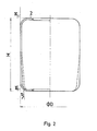
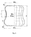
- 1 to 3 represent the profiles of the previously known and commonly used rolling membranes.
- the rolling membrane 2 illustrated in FIG. 1, which rolls on the associated piston, is characterized in that it is provided with a jacket 1.
- the cord reinforcement is made from at least two intersecting inserts.
- the diameter of the membranes changes during the suspension in such a way that the diameter remains constant in the section under the jacket 1, while an increase can be observed in the sections without reinforcement, the cord angle of the inserts of the vulcanized membrane between 40 ° and 50 0 lies.
- the membrane profile shown in Fig. 1 can be used in a relatively limited area, namely only in buses.
- the disadvantage of this solution is that in the spring-loaded (unloaded) state, the jacket 1 often slips off the rolling membrane 2, as a result of which both the membrane 2 and the jacket 1 are destroyed.
- angles of the membrane profile are as follows: or
- the cord reinforcement used consists of at least two intersecting inserts, the cord fibers forming an angle with the longitudinal axis under load and excess pressure, at which the diameter can only change slightly (equilibrium angle).
- this solution which is otherwise quite advantageous, still has the disadvantage that the suctioning in of the membrane wall during the rebounding (in an unloaded state) could not be eliminated; the line that accumulates at the vulcanized belt ends and that accumulates tension can cause the membrane to become damaged.
- a rubber membrane profile design is also known, in which the flange of the membrane bends outwards and is permanently connected to a clamping metal structure. In this case too, the working section of the membrane is cylindrical.
- the known disadvantages could not be eliminated here either.
- a membrane which, in the basic state (ie without overpressure), can be characterized by a diameter which changes along the generatrix of the hollow body, the diameter being from the lower or starting from the upper flanges of the membrane and increasingly determining the profile of a double truncated cone to a different degree.
- the reinforcement system of the roll membrane according to the invention can be characterized in that it consists of at least two inserts containing intersecting fibers, in which the value of the cord angle (the cord angle is understood to mean an angle which is at a point through the tested point of the membrane) the main axis of rotation of the membrane is perpendicular to the plane and is enclosed by the tangent drawn to the tested point and the cord fiber, understood) changes constantly along the membrane generators, namely, starting from the largest diameter (where the cord angle is 25-40 °), in one direction up to 40 - 45 °, in the other direction up to 50 - 60 °.
- FIG. 4 This shows the rolling membrane 2 in the unloaded state, in which the diameters along the generatrix of the hollow body, starting from the upper and lower flange of the rolling membrane, tending towards the center, increase, in different masses, until they reach a common maximum diameter.
- the height H of the roll membrane 2 according to the invention suitably corresponds to approximately 0.5-2.5 of the diameter, the diameter changing along the entire generatrix. Between the two flanges, the diameter takes the boundary value D max. at.
- the taper of the two truncated cones coinciding with their base is different. This means that the angle that is parallel to the longitudinal axis of the hollow body and the generatrix.
- the base material of the roll membrane according to the invention can be natural or synthetic rubber.
- the tape roll is made of artificial silk, polyamide, glass or steel fiber.
- the membrane profile described above and the changing angular value of the reinforcing inserts along the generators influence the operation of the rolling membrane in a simple but advantageous manner.
- the tape roll fatigue is reduced.
- the resistance to the unfavorable influences of the extreme conditions is increased, all the advantages mentioned being achieved without the use of accessory inserts or a reinforcing jacket and without increasing the wall thickness.
- the diameter only increases to a certain extent, the increase in diameter being smaller on the non-rolling surface and the position being more stable in the spring-out state. Damaged twists, dents or deformations do not occur.
- roller membrane according to the invention Another advantage of the roller membrane according to the invention is that the damaged pressure load can be significantly reduced, since primarily the tensile load dominates; at the same time, the wall thickness of the roll membrane according to the invention (compared with the known solutions) is smaller, as a result of which the heating caused by the folding and pressure deformation and its harmful effects are avoided.
- the air spring containing the roll membrane according to the invention can be used in various motor vehicles, from buses to articulated lorries. It ensures optimal suspension, self-vibration and operation as a lever without the need for a separate jacket, belt or any other (additional) element.
Abstract
Description
Die Erfindung betrifft eine Rollmembran bzw. einen Rollbalg für Luftfedern, gemäß den Merkmalen des Oberbegriffs des Anspruchs 1, insbesondere für bei Lastkraftfahrzeugen, Autobussen, Sattelschleppern und ähnlichen Fahrzeugen zur Aufhängung verwendeten Luftfedern.The invention relates to a rolling diaphragm or a rolling bellows for air springs, according to the features of the preamble of claim 1, in particular for air springs used for suspension in trucks, buses, articulated vehicles and similar vehicles.
Insbesondere bezieht sich die Erfindung einerseits auf die neuartige Gestaltung der Rollmembran, andererseits auf die Gestaltung der Winkelwerte der in der Bandrolle vorhandenen Kordfasern.In particular, the invention relates on the one hand to the novel design of the roll membrane, on the other hand to the design of the angle values of the cord fibers present in the tape roll.
Es ist bekannt, daß die Beanspruchung der Rollmembran einer Luftfeder bereits im Laufe der Auffüllung mit Luft anfängt. Die Höhe des im Inneren der Luftfeder sich ausgestaltenden Druckes wird sich demnach ändern, ob eine Aus-oder Einfederung stattfindet. Im Laufe des Gebrauchs wird infolge der Deformation der Membran oder der Hystherese des Gummis ein Teil der Falt- und Deformationsarbeit in Wärme umgewandelt. Aus diesem Standpunkt heraus wird der Wandstärke der Membran große Bedeutung beigemessen, da bei einer dickeren Membranwand die infolge der Falt- und Deformationsarbeit auftretende Wärmebildung höher ist als bei einer dünneren Membranwand.It is known that the stress on the rolling membrane of an air spring begins with air during the filling. The level of the pressure developing in the interior of the air spring will therefore change whether a deflection or deflection takes place. In the course of use, part of the folding and deformation work is converted into heat due to the deformation of the membrane or the hysteresis of the rubber. From this point of view, the Wall thickness of the membrane is of great importance, since the heat generated as a result of the folding and deformation work is higher in the case of a thicker membrane wall than in the case of a thinner membrane wall.
Ein weiterer Zusammenhang kann zwischen der Längsabmessung bzw. dem Querschnitt und dem Mass der Erwärmung beobachtet werden. Unter gleichen Umständen und bei einem gleichen Innendruck wird sich eine Membran mit einem kleineren Durchmesser und/oder geringerer Länge - d.h. mit einem kleineren Luftraum - stärker erwärmen.Another connection can be observed between the longitudinal dimension or the cross section and the degree of heating. Under the same circumstances and with the same internal pressure, a membrane with a smaller diameter and / or shorter length - i.e. with a smaller airspace - warm up more.
Selbstverständlich wird die Deformation der Luftfedermembranen auch von den Wegverhälthissen bedeutend beeinflußt. Die Membranen sind auf einer Fahrstraße von durchschnittlicher Qualität mehreren Tausend von Ein- und Ausfederungen während einer Stunde ausgesetzt. Die statistischen Prüfungen haben bestätigt, daß bei veränderlichen Weg-, Geschwindigkeits- und Belastungsverhältnissen nach dem Ablauf von 50 000 Km die Luftfedermembran 6,5 x 10⁶ Faltzyklen unterworfen worden ist, d.h. daß die Membran während ihrer gesamten Lebensdauer das Vielfache dieses Wertes ertragen muß. Während des erwähnten Federspiels sind die festigkeitstragenden Kordfasern in der Membranwand einer Zug- und Druckbeanspruchung ausgesetzt. Die Druckbeanspruchung ist aber für die Kordfasern sehr schädlich. Aufgrunddessen muß nach einer Herabsetzung derselben gestrebt werden.Of course, the deformation of the air spring membranes is also significantly influenced by the travel conditions. The membranes are exposed to several thousand deflections and deflections in an hour on an average quality route. The statistical tests have confirmed that in the event of variable path, speed and load conditions after the expiration of 50,000 km, the air spring membrane has been subjected to 6.5 x 10 6 folding cycles, ie the membrane has to endure a multiple of this value over its entire service life . During the spring play mentioned, the strength-supporting cord fibers in the membrane wall are exposed to tensile and compressive stress. The pressure load is very harmful for the cord fibers. Because of this, efforts must be made to reduce it.
Andererseits ist die Tatsache bekannt, daß im allgemeinen die Fahrzeughersteller neben der Sicherstellung der Federung auch die Forderung stellen, daß die Luftfederung zum Anheben eines entsprechenden Teiles der Aufhängung geeignet ist. Eine weitere Forderung besteht darin, - insbesondere, wenn eine leichte, gegenüber Erschütterungen empfindliche Fracht in großen Mengen transportiert wird - daß in dem Fall, in dem eine vollkommene Belastung des Fahrzeugs praktisch nicht realisiert wird, die eine Achse (aus auf die Schwingungsdämpfung gerichteten Überlegungen) auch während des Betriebes angehoben wird, wodurch auch unter extremen Federungsverhältnissen annähernd gleiche Federungseigenschaften erreicht werden können. Bei zahlreichen Kraftfahrzeugen, Anhängern, Sattelschleppern usw. trat die Verwendung der Luftfedern in den Vordergrund, da auf diese Weise eindeutig bessere Federungscharakteristiken erreicht werden konnten. Gleicherweise wird das Luftfedersystem vorteilhaft bei Silofahrzeugen, Behälterwagen usw. verwendet, da dadurch nicht nur die Qualität der Federung während der Leerfahrten verbessert werden kann, sondern das ganze Fahrzeug geschont wird. Desweiteren wird das Anheben der Räder in einen unbelasteten Zustand ermöglicht.On the other hand, the fact is known that, in addition to ensuring the suspension, the vehicle manufacturers generally also make the requirement that the air suspension is suitable for lifting a corresponding part of the suspension. Another requirement is - especially if a slight, against shocks sensitive cargo is transported in large quantities - that in the event that a complete load of the vehicle is not practically realized, the one axle (due to vibration damping considerations) is raised during operation, so that even under extreme suspension conditions approximately the same Suspension properties can be achieved. In numerous motor vehicles, trailers, articulated lorries, etc., the use of air springs came to the fore, since clearly better suspension characteristics could be achieved in this way. Likewise, the air suspension system is advantageously used in silo vehicles, container trucks, etc., since not only can the quality of the suspension be improved during empty runs, but the entire vehicle is protected. Furthermore, the lifting of the wheels in an unloaded state is made possible.
Bei dem Betrieb der Kraftfahrzeuge kommt ein extremer Federungszustand recht oft vor, der darin besteht, daß der in der Luftfeder herrschende Luftdruck auf einen niedrigeren Wert abfällt. Während des Transports (Schifftransport, per Bahn) eines Fahrzeugs tritt auch ein Zustand ein, in dem kein Überdruck in der Luftfeder gegeben ist. In diesem Zustand ist aufgrund des Anhebens des Fahrzeuges und der dadurch gegebenen Entlastung der jeweiligen Luftfeder der im Inneren der Membran herrschende Druck niedriger als der atmosphärische Druck, wodurch eine negative Krümmung in der Rollmembran entsteht, die beim Aufstellen des Fahrzeuges auf seine Räder zu schadhaften Deformationen und Einbeulungen führen kann.In the operation of motor vehicles, an extreme suspension condition occurs quite often, which consists in the air pressure prevailing in the air spring dropping to a lower value. During the transport (ship transport, by train) of a vehicle, a condition also occurs in which there is no overpressure in the air spring. In this state, due to the lifting of the vehicle and the resulting relief of the respective air spring, the pressure prevailing inside the membrane is lower than the atmospheric pressure, which results in a negative curvature in the rolling membrane, which leads to defective deformations when the vehicle is placed on its wheels and can cause denting.
Ein ähnlicher kritischer Zustand entsteht bei einem in der Garagenposition vorgenommenen Radwechsel, d.h. bei allen Gelegenheiten bei denen die Karosserie plötzlich angehoben wird, da dadurch in der Membran ein verminderter Überdruck und ein großes Volumen entstehen.A similar critical condition arises when the wheel is changed in the garage position, ie on all occasions when the body is suddenly raised, since this results in a reduced overpressure in the membrane and create a large volume.
Es kann festgestellt werden, daß das Profil einer üblich ausgestalteten Rollmembran sich in den Extremfällen ändert, bei einer wiederholten Belastung sich ausbeult und leicht zerstört wird.It can be established that the profile of a conventionally designed rolling membrane changes in extreme cases, bulges out under repeated loading and is easily destroyed.
Um diese Erscheinungen vermeiden zu können, wurden äußere Versteifungen, z.B. die Anwendung eines Metallmantels vorgeschlagen. Die Lösung hatte jedoch nicht zu den gewünschten Resultaten geführt, da der Mantel leicht von der Rollmembran abrutschte und deshalb nicht imstande war, seine Funktion zu erfüllen.In order to avoid these phenomena, external stiffeners, e.g. proposed the use of a metal jacket. However, the solution did not produce the desired results because the jacket slipped easily from the roll membrane and was therefore unable to perform its function.
Aus der HU-PS 167 387 ist eine Lösung bekannt, bei der zur Verminderung der oben geschilderten schadhaften Erscheinungen unter, zwischen oder über einem oder mehreren, mit ihren übereinander angeordneten Fasersystemen Rhomben bildenden Stoffeinsätzen der Rollmembran, mindestens im Bereich eines Abschnittes der Mantelfläche des zylindrischen Teiles der Membran ein oder mehrere weitere Einsätze vorgesehen ist (sind), der (die) an den erst erwähnten Einsätzen befestigt ist (sind) und dessen (deren) Fasersystem die erwähnten Fäserrhomben in Faserdreiecken unterteilt. Diese Lösung (sog. "Membran mit Gürteleinsatz") ergibt in den gegebenen Abschnitten eine gewisse Steifheit der Membran, die das Maß der Deformation und die schadhaften Einflüsse verringert.A solution is known from HU-PS 167 387 in which, in order to reduce the defective phenomena described above, under, between or above one or more fabric inserts of the roll membrane forming rhombuses with their fiber systems arranged one above the other, at least in the region of a section of the lateral surface of the cylindrical one Part (s) of the membrane is (are) provided, which is (are) attached to the first-mentioned inserts and whose (whose) fiber system divides the aforementioned fiber lozenges into fiber triangles. This solution (so-called "membrane with belt insert") results in a certain stiffness of the membrane in the given sections, which reduces the degree of deformation and the harmful influences.
Der Erfindung liegt die Aufgabe zugrunde eine Rollmembran für Luftfedern zu entwickeln, in deren Kordstruktur die Zugbeanspruchung dominiert und die Druckbeanspruchung reduziert wird. Darüber hinaus soll auf der Basis der oben beschriebenen Verstärkungswirkung eine äußerst günstige und entsprechend weiche Federung erreicht werden; weiterhin besteht die Forderung, daß bei einem niedrigen Druckwert eine Beulung.der Membran kein Schadhaftwerden hervorruft; der letzterwähnte Umstand verlängert die Lebensdauer der Membran ohne Erfordernis der Verwendung eines separaten äußeren Mantels oder eines zusätzlichen Einsatzes (Gürtels). Die Aufgabe wird bei einer Rollmembran der vorausgesetzten Art dadurch gelöst, daßThe invention is based on the object of developing a rolling membrane for air springs, in the cord structure of which the tensile stress dominates and the compressive stress is reduced. In addition, an extremely favorable and correspondingly soft suspension is to be achieved on the basis of the reinforcing effect described above; continue there is a requirement that a bulge of the membrane does not cause damage at a low pressure value; the latter circumstance extends the life of the membrane without the need to use a separate outer jacket or an additional insert (belt). The problem is solved in a rolling membrane of the type assumed that
in einem Zustand ohne Überdruck die Durchmesser des Hohlkörpers der Rollmembran sich entlang der Erzeugenden ändern und zwar derart, daß von den unteren und oberen Flanschen der Rollmembran ausgehend die Durchmesser in einem unterschiedlichen Maß zunehmend das Profil eines Doppelstumpfkegels bestimmen und daß ferner die Rollmembran mindestens zwei einander kreuzende Fasern enthaltende Einsätze auf--weist, bei denen der Wert des Kordwinkels sich entlang der Erzeugenden des Hohlkörperprofils ständig ändert.in a state without overpressure, the diameters of the hollow body of the rolling membrane change along the generatrices in such a way that starting from the lower and upper flanges of the rolling membrane, the diameters increasingly determine the profile of a double-cone to a different degree, and furthermore that the rolling membrane at least two each other Inserts containing crossing fibers - in which the value of the cord angle changes constantly along the generatrix of the hollow body profile.
Zweckmäßige Ausgestaltungen der erfindungsgemäßen Rollmembran ergeben sich aus den übrigen Ansprüchen.Expedient configurations of the roller membrane according to the invention result from the remaining claims.
Die erfindungsgemäße Lösung beruht auf der Erkenntnis, daß durch die Modifizierung des Profils der Rollmembran aufgrund der gegenseitigen Stützwirkung des Doppelkegels und die derart erzeugten Kordwinkel die Membran ausgesteift und gegenüber Deformationen geschützt wird (in vergleichgarer Weise ist eine gerippte Platte steifer als eine plane), wodurch die aus dem Stand der Technik resultierenden Nachteile behoben werden. Die erfingungsgemäße Gestaltung ergibt - mit den bekannten Luftfedermembranen mit diagonaler Querverstärkung verglichen - eine Membran mit wesentlich vorteilhafteren Charakteristiken.The solution according to the invention is based on the knowledge that by modifying the profile of the rolling membrane due to the mutual support effect of the double cone and the cord angles thus generated, the membrane is stiffened and protected against deformation (in a comparable way, a ribbed plate is stiffer than a plane), which means that the disadvantages resulting from the prior art are eliminated. The inventive design results - compared to the known air spring membranes with diagonal transverse reinforcement - a membrane with much more advantageous characteristics.
Mit den eine äußere Stützanordnung umfassenden Lösungen verglichen, ist die erfindungsgemäße Lösung ebenfalls eine vorteilhafte Weiterentwicklung; in diesem Fall werden die Luftfedermembranen, die mit den mit der Bandrolle mitvulkanisierten peripheralen und in Richtung der Erzeugenden liegenden Verstärkungseinsätzen versteift sind, weiterentwickelt und deren Federungsparameter verbessert.With the solutions comprising an outer support arrangement compared, the solution according to the invention is also an advantageous further development; In this case, the air spring membranes, which are stiffened with the reinforcing inserts co-vulcanized with the tape roll and lying in the direction of the generators, are further developed and their suspension parameters are improved.
Die Fig. 1 bis 3 stellen die Profile der bisher bekannten und allgemein verwendeten Rollmembranen dar.1 to 3 represent the profiles of the previously known and commonly used rolling membranes.
Die in Fig. 1 veranschaulichte, an dem zugehörigen Kolben rollende Rollmembran 2 ist dadurch gekennzeichnet, daß sie mit einem Mantel 1 versehen ist. Bezüglich der Gestaltung des Profils der Rollmembran ist festzustellen, daß die Höhe H der zylindrischen Membran dem Durchmesser D gleich ist oder diesen unterschreitet; d.h.daß das Verhältnis H/D gleich H/D = 1, vorzugsweise 0,65-1, ist.The
Bei dieser Lösung ist die Kordverstärkung aus mindestens zwei, einander kreuzenden Einsätzen gefertigt. Der Durchmesser der Membranen ändert sich während der Federung, und zwar derart, daß der Durchmesser in dem Abschnitt unter dem Mantel 1 konstant bleibt, während in den Abschnitten ohne Verstärkung eine Zunahme beobachtet werden kann, wobei der Kordwinkel der Einsätze der vulkanisierten Membran zwischen 40° und 500 liegt.In this solution, the cord reinforcement is made from at least two intersecting inserts. The diameter of the membranes changes during the suspension in such a way that the diameter remains constant in the section under the jacket 1, while an increase can be observed in the sections without reinforcement, the cord angle of the inserts of the vulcanized membrane between 40 ° and 50 0 lies.
Das in Fig. 1 dargestellte Membranprofil kann auf einem verhältnismäßig beschränkten Gebiet, nämlich ausschließlich bei Autobussen verwendet werden. Der Nachteil dieser Lösung besteht darin, daß in dem ausgefederten (unbelasteten) Zustand der Mantel 1 oft von der Rollmembran 2 abrutscht, wodurch sowohl die Membran 2 als auch der Mantel 1 zerstört werden.The membrane profile shown in Fig. 1 can be used in a relatively limited area, namely only in buses. The disadvantage of this solution is that in the spring-loaded (unloaded) state, the jacket 1 often slips off the
Die in Fig. 2 gezeigte, in den Einsätzen unter einem sog. Gleichgewichtswinkel angeordneten Kordfasern enthaltende, ggf. einseitig konisch ausgestaltete Rollmembran 2 ist dadurch gekennzeichnet, daß die Länge H der zylindrischen (oder einseitig konischen) Membran 2 dem Durchmesser D gleich ist oder diesen überschreitet, d.h., daß H = d und H - 1 - 2 D ist.The
Die Winkel des Membranprofils sind wie folgt:![]()


![]()
Auch in diesem Fall besteht die verwendete Kordverstärkung aus wenigstens zwei, einander kreuzenden Einsätzen, wobei unter Belastung und Überdruck die Kordfasern mit der Längsachse einen Winkel einschließen, unter dem der Durchmesser sich nur gering verändert kann (Gleichgewichtswinkel).In this case too, the cord reinforcement used consists of at least two intersecting inserts, the cord fibers forming an angle with the longitudinal axis under load and excess pressure, at which the diameter can only change slightly (equilibrium angle).
Diese Gestaltung ist zwar schon viel besser als die in der Fig. 1 veranschaulichte, mit dem Mantel 1 versehene Rollmembran 2, aber auch bei dieser Gestaltung kommt die Verdrückung in einem unbelasteten Zustand zustande.Although this design is already much better than the
Die Fig. 3 stellt die Lösung nach der bereits zitierten HU-PS 167 387 dar; bei dieser Rollmembran 2 beträgt das Verhältnis Höhe (H) und durchschnittlicher Durchmesser D durchschnittlich H![]()
![]()
Ferner ergibt sich:

Unter Zuhilfenahme des Versteifungssystems des Abschnitts 1 ist es gelungen, bei dieser Lösung das Beulen zu.vermindern; eine vollkommene Beseitigung konnte aber nicht erreicht werden. So weist diese im übrigen recht vorteilhafte Lösung noch immer den Nachteil auf, daß das Einsaugen der Membranwand bei der Ausfederung (in einem unbelasteten Zustand) nicht eliminiert werden konnte; dabei kann die bei den einvulkanisierten Gürtelenden entstehende, die Spannung ansammelnde Linie ein Schadhaftwerden der Membran hervorrufen.With the aid of the stiffening system in section 1, it was possible to buckle this solution . Reduce; however, a complete elimination could not be achieved. Thus, this solution, which is otherwise quite advantageous, still has the disadvantage that the suctioning in of the membrane wall during the rebounding (in an unloaded state) could not be eliminated; the line that accumulates at the vulcanized belt ends and that accumulates tension can cause the membrane to become damaged.
Es ist weiterhin eine Gummimembran-Profilgestaltung bekannt, bei der der Flansch der Membran sich nach außen biegt und mit einer einspannenden Metallstruktur unlösbar verbunden ist. Auch in diesem Fall ist der arbeitende Abschnitt der Membran zylindrisch ausgestaltet. Die bekannten Nachteile konnten auch hier nicht beseitigt werden.A rubber membrane profile design is also known, in which the flange of the membrane bends outwards and is permanently connected to a clamping metal structure. In this case too, the working section of the membrane is cylindrical. The known disadvantages could not be eliminated here either.
Im Sinne der erfindungsgemäßen Lösung werden die Nachteile der bekannten Gestaltungen dadurch beseitigt, daß eine Membran verwendet wird, die in dem Grundzustand (d.h. ohne Überdruck) durch sich entlang der Erzeugenden des Hohlkörpers ändernden Durchmesser charakterisiert werden kann, wobei die Durchmesser von den unteren bzw. oberen Flanschen der Membran ausgehend und in einem voneinander abweichenden Maß zunehmend das Profil eines doppelten Stumpfkegels bestimmen.In the sense of the solution according to the invention, the disadvantages of the known designs are eliminated in that a membrane is used which, in the basic state (ie without overpressure), can be characterized by a diameter which changes along the generatrix of the hollow body, the diameter being from the lower or starting from the upper flanges of the membrane and increasingly determining the profile of a double truncated cone to a different degree.
Das Verstärkungssystem der erfindungsgemäßen Rollmembran kann dadurch gekennzeichnet werden, daß es aus mindestens zwei, einander kreuzenden Fasern'enthaltenen Einsätzen besteht, bei der der Wert des Kordwinkels (unter dem Kordwinkel wird ein Winkel verstanden, der in einer durch den geprüften Punkt der Membran gelegten zu der Hauptdrehachse der Membran senkrechten Ebene liegt und von der zu dem geprüften Punkt gezogene Tangente und der Kordfaser umschlossen wird, verstanden) sich entlang der Membranerzeugenden ständig ändert, und zwar, von dem größten Durchmesser ausgehend (wo der Kordwinkel 25 - 40° beträgt), in der einen Richtung bis 40 - 45°, in der anderen Richtung bis 50 - 60°.The reinforcement system of the roll membrane according to the invention can be characterized in that it consists of at least two inserts containing intersecting fibers, in which the value of the cord angle (the cord angle is understood to mean an angle which is at a point through the tested point of the membrane) the main axis of rotation of the membrane is perpendicular to the plane and is enclosed by the tangent drawn to the tested point and the cord fiber, understood) changes constantly along the membrane generators, namely, starting from the largest diameter (where the cord angle is 25-40 °), in one direction up to 40 - 45 °, in the other direction up to 50 - 60 °.
Die erfindungsgemäße Lösung ist näher in der Fig. 4 dargestellt. Diese zeigt die Rollmembran 2 im unbelasteten Zustand, in dem die Durchmesser entlang der Erzeugenden des Hohlkörpers von dem oberen und unteren Flansch der Rollmembran ausgehend, nach der Mitte tendierend, zunehmen, und zwar in unterschiedlichen Massen, bis sie einen gemeinsamen maximalen Durchmesser erreichen. Die Höhe H der erfindungsgemäßen Rollmembran 2 entspricht zweckmäßig etwa dem 0,5 - 2,5 des Durchmessers, wobei der Durchmesser sich entlang der gesamten Erzeugenden ändert. Zwischen den beiden Flanschen nimmt der Durchmesser den Randwert D max. an. Die Konizität der beiden mit ihrer Basis zusammenfallenden Stumpfkegel ist unterschiedlich. Dies bedeutet, daß der Winkel, der von der zur Längsachse des Hohlkörpers parallelen und die Erzeugende. am größten Durchmesser tangierenden Geraden und von der Erzeugenden des Mantels des jeweiligen Stumpfkegels umschlossen ist, bei dem oberen Stumpfkegel tl und dem unteren Stumpfkegel δ2 ist, wobei δ1 - 1 - 5°, δ2 = 2 10° und δ2=2δ1. δ1≠δ2.The solution according to the invention is shown in more detail in FIG. 4. This shows the
Der Grundwerkstoff der erfindungsgemäßen Rollmembran kann natürlicher oder synthetischer Kautschuk sein. Die Bandrolle wird aus Kunstseide, Polyamid, Glas- bzw. Stahlfaser hergestellt.The base material of the roll membrane according to the invention can be natural or synthetic rubber. The tape roll is made of artificial silk, polyamide, glass or steel fiber.
Das oben beschriebene Membranprofil und der entlang der Erzeugenden sich ändernde Winkelwert der Verstärkungseinsätze beeinflussen auf eine einfache, jedoch vorteilhafte Weise den Betrieb der Rollmembran. Die Ermüdung der Bandrolle wird vermindert. Gleichzeitig wird die Beständigkeit gegenüber den ungünstigen Einflüssen der extremen Zustände erhöht, wobei alle die erwähnten Vorteile ohne die Anwendung der akzessorischen Einsätze, bzw. eines verstärkenden Mantels und ohne die Erhöhung der Wandstärke erreicht werden.The membrane profile described above and the changing angular value of the reinforcing inserts along the generators influence the operation of the rolling membrane in a simple but advantageous manner. The tape roll fatigue is reduced. At the same time, the resistance to the unfavorable influences of the extreme conditions is increased, all the advantages mentioned being achieved without the use of accessory inserts or a reinforcing jacket and without increasing the wall thickness.
Wenn die erfindungsgemäße Rollmembran unter Druck gesetzt wird und eine Federung stattfindet, nimmt der Durchmesser nur bis zu einem gewissen Maß zu, wobei auf der nicht rollenden Fläche die Zunahme des Durchmessers geringer und in dem ausgefederten Zustand die Position stabiler ist. Schadhafte Verwindungen, Einbeulungen bzw. Deformationen treten nicht auf.If the roll membrane according to the invention is pressurized and suspension takes place, the diameter only increases to a certain extent, the increase in diameter being smaller on the non-rolling surface and the position being more stable in the spring-out state. Damaged twists, dents or deformations do not occur.
Ein weiterer Vorteil der erfindungsgemäßen Rollmembran liegt darin, daß die schadhafte Druckbeanspruchung bedeutend verringert werden kann, da in erster Linie die Zugbeanspruchung dominiert; gleichzeitig ist die Wandstärke der erfindungsgemäßen Rollmembran (mit den bekannten Lösungen verglichen) geringer, wodurch die von der Falt- und Druckdeformation hervorgerufene Erwärmung und deren schädliche Auswirkungen vermieden werden.Another advantage of the roller membrane according to the invention is that the damaged pressure load can be significantly reduced, since primarily the tensile load dominates; at the same time, the wall thickness of the roll membrane according to the invention (compared with the known solutions) is smaller, as a result of which the heating caused by the folding and pressure deformation and its harmful effects are avoided.
Dadurch, daß entlang der Erzeugenden des Profils der Rollmembran die Durchmesser sich ständig ändern, wird eine äußerst günstige Verstärkung erreicht, da die in den Verstärkungseinsätzen sich ergebenden Kordwinkel sich ebenfalls ändern, und zwar, von dem größten Durchmesser ausgehend, in beiden Richtungen asymmetrisch.The fact that the diameters change constantly along the generatrix of the profile of the rolling membrane is a extremely favorable reinforcement achieved, since the cord angles resulting in the reinforcement inserts also change, starting from the largest diameter, asymmetrically in both directions.
Auf diese Weise kann das Anwendungsgebiet der erfindungsgemäßen Luftfeder bedeutend erweitert werden. Die die erfindungsgemäße Rollmembran enthaltende Luftfeder kann in unterschiedlichen Kraftfahrzeugen, vom Autobus bis zum Sattelschlepper, verwendet werden. Sie sichert eine optimale Federung, Selbstschwingungszahl und einen als Hebel wirkenden Betrieb, ohne daß ein separater Mantel, Gürtel oder ein sonstiges (zusätzliches) Element nötig wäre.In this way, the field of application of the air spring according to the invention can be expanded significantly. The air spring containing the roll membrane according to the invention can be used in various motor vehicles, from buses to articulated lorries. It ensures optimal suspension, self-vibration and operation as a lever without the need for a separate jacket, belt or any other (additional) element.
Claims (4)


Applications Claiming Priority (2)
| Application Number | Priority Date | Filing Date | Title |
|---|---|---|---|
| HU75281 | 1981-03-25 | ||
| HU8181752A HU180404B (en) | 1981-03-25 | 1981-03-25 | Rolling membrane for air springs |
Publications (3)
| Publication Number | Publication Date |
|---|---|
| EP0062112A2 true EP0062112A2 (en) | 1982-10-13 |
| EP0062112A3 EP0062112A3 (en) | 1983-03-30 |
| EP0062112B1 EP0062112B1 (en) | 1985-12-04 |
Family
ID=10951159
Family Applications (1)
| Application Number | Title | Priority Date | Filing Date |
|---|---|---|---|
| EP81110419A Expired EP0062112B1 (en) | 1981-03-25 | 1981-12-14 | Rolling diaphragm for air springs |
Country Status (9)
| Country | Link |
|---|---|
| EP (1) | EP0062112B1 (en) |
| AT (1) | ATE16839T1 (en) |
| DD (1) | DD201721A5 (en) |
| DE (1) | DE3173156D1 (en) |
| HU (1) | HU180404B (en) |
| PL (1) | PL139303B1 (en) |
| RO (1) | RO83100B (en) |
| SU (1) | SU1215629A3 (en) |
| YU (1) | YU43613B (en) |
Cited By (5)
| Publication number | Priority date | Publication date | Assignee | Title |
|---|---|---|---|---|
| EP0413420A1 (en) * | 1989-07-18 | 1991-02-20 | General Motors Corporation | Spliced air sleeve assembly for air spring damper |
| DE29517741U1 (en) * | 1995-11-09 | 1996-01-04 | Rommel Juergen Gmbh | Roller bellows without radial guides as a single and multi-stage design with roller folds in the direction of actuation |
| WO2000043692A1 (en) * | 1999-01-21 | 2000-07-27 | Phoenix Aktiengesellschaft | Pneumatic suspension system |
| DE102005041800B3 (en) * | 2005-09-02 | 2007-03-01 | Otto Sauer Achsenfabrik Gmbh | Air bellow for pneumatic spring, has axial sided area laid out so that area receives key according to complete aspect ratio of air bellow with movement of axial sided area to assembly sided area based on shape memory to roll over plunger |
| EP2280186A3 (en) * | 2009-07-31 | 2011-05-11 | SAF-HOLLAND GmbH | Air bellows for a pneumatic spring |
Citations (9)
| Publication number | Priority date | Publication date | Assignee | Title |
|---|---|---|---|---|
| CH335258A (en) * | 1956-01-27 | 1958-12-31 | Dunlop Rubber Co | Bellows device |
| FR1229277A (en) * | 1958-08-04 | 1960-09-06 | Us Rubber Co | Diaphragm for pneumatic spring, and its manufacturing process |
| DE2030342A1 (en) * | 1969-06-20 | 1971-01-07 | Autobrzdy Jablonec, narodni podnik, Gablonz, Neiße (Tschechoslowakei) | Pneumatic spring |
| DE2023105A1 (en) * | 1970-05-06 | 1971-12-09 | Orszagos Gumiipari Vall | Roll bellows air spring |
| DE2310574A1 (en) * | 1972-03-02 | 1973-09-06 | Dunlop Ltd | ELASTOMER BRACKETS |
| AT340209B (en) * | 1975-04-07 | 1977-12-12 | Taurus Gumiipari Vallalat | BELLOWS FOR AIR SPRINGS |
| DE2836662B1 (en) * | 1978-08-22 | 1979-10-11 | Daimler Benz Ag | Air springs, especially for motor vehicles |
| DE2759433B1 (en) * | 1977-11-12 | 1979-11-15 | Daimler Benz Ag | Air spring for motor vehicles |
| DE2905791A1 (en) * | 1979-02-15 | 1980-08-28 | Continental Gummi Werke Ag | Vehicle air suspension system rolling bellows - has reinforcing fibrous members inclined to transverse plane |
-
1981
- 1981-03-25 HU HU8181752A patent/HU180404B/en not_active IP Right Cessation
- 1981-12-14 DE DE8181110419T patent/DE3173156D1/en not_active Expired
- 1981-12-14 EP EP81110419A patent/EP0062112B1/en not_active Expired
- 1981-12-14 AT AT81110419T patent/ATE16839T1/en not_active IP Right Cessation
- 1981-12-16 SU SU813367548A patent/SU1215629A3/en active
- 1981-12-17 DD DD81235904A patent/DD201721A5/en not_active IP Right Cessation
-
1982
- 1982-01-22 RO RO106408A patent/RO83100B/en unknown
- 1982-01-27 PL PL1982234848A patent/PL139303B1/en unknown
- 1982-02-25 YU YU421/82A patent/YU43613B/en unknown
Patent Citations (9)
| Publication number | Priority date | Publication date | Assignee | Title |
|---|---|---|---|---|
| CH335258A (en) * | 1956-01-27 | 1958-12-31 | Dunlop Rubber Co | Bellows device |
| FR1229277A (en) * | 1958-08-04 | 1960-09-06 | Us Rubber Co | Diaphragm for pneumatic spring, and its manufacturing process |
| DE2030342A1 (en) * | 1969-06-20 | 1971-01-07 | Autobrzdy Jablonec, narodni podnik, Gablonz, Neiße (Tschechoslowakei) | Pneumatic spring |
| DE2023105A1 (en) * | 1970-05-06 | 1971-12-09 | Orszagos Gumiipari Vall | Roll bellows air spring |
| DE2310574A1 (en) * | 1972-03-02 | 1973-09-06 | Dunlop Ltd | ELASTOMER BRACKETS |
| AT340209B (en) * | 1975-04-07 | 1977-12-12 | Taurus Gumiipari Vallalat | BELLOWS FOR AIR SPRINGS |
| DE2759433B1 (en) * | 1977-11-12 | 1979-11-15 | Daimler Benz Ag | Air spring for motor vehicles |
| DE2836662B1 (en) * | 1978-08-22 | 1979-10-11 | Daimler Benz Ag | Air springs, especially for motor vehicles |
| DE2905791A1 (en) * | 1979-02-15 | 1980-08-28 | Continental Gummi Werke Ag | Vehicle air suspension system rolling bellows - has reinforcing fibrous members inclined to transverse plane |
Cited By (8)
| Publication number | Priority date | Publication date | Assignee | Title |
|---|---|---|---|---|
| EP0413420A1 (en) * | 1989-07-18 | 1991-02-20 | General Motors Corporation | Spliced air sleeve assembly for air spring damper |
| DE29517741U1 (en) * | 1995-11-09 | 1996-01-04 | Rommel Juergen Gmbh | Roller bellows without radial guides as a single and multi-stage design with roller folds in the direction of actuation |
| WO2000043692A1 (en) * | 1999-01-21 | 2000-07-27 | Phoenix Aktiengesellschaft | Pneumatic suspension system |
| DE10001018B4 (en) * | 1999-01-21 | 2011-03-31 | Vibracoustic Gmbh & Co. Kg | Air suspension system |
| DE102005041800B3 (en) * | 2005-09-02 | 2007-03-01 | Otto Sauer Achsenfabrik Gmbh | Air bellow for pneumatic spring, has axial sided area laid out so that area receives key according to complete aspect ratio of air bellow with movement of axial sided area to assembly sided area based on shape memory to roll over plunger |
| US8240643B2 (en) | 2005-09-02 | 2012-08-14 | Saf-Holland Gmbh | Pneumatic suspension bellows |
| EP2280186A3 (en) * | 2009-07-31 | 2011-05-11 | SAF-HOLLAND GmbH | Air bellows for a pneumatic spring |
| EP2280186B1 (en) | 2009-07-31 | 2017-03-15 | SAF-HOLLAND GmbH | Air bellows for a pneumatic spring |
Also Published As
| Publication number | Publication date |
|---|---|
| EP0062112B1 (en) | 1985-12-04 |
| PL234848A1 (en) | 1982-09-27 |
| RO83100A (en) | 1984-03-15 |
| EP0062112A3 (en) | 1983-03-30 |
| HU180404B (en) | 1983-03-28 |
| ATE16839T1 (en) | 1985-12-15 |
| SU1215629A3 (en) | 1986-02-28 |
| PL139303B1 (en) | 1987-01-31 |
| DE3173156D1 (en) | 1986-01-16 |
| DD201721A5 (en) | 1983-08-03 |
| RO83100B (en) | 1984-03-30 |
| YU42182A (en) | 1986-06-30 |
| YU43613B (en) | 1989-08-31 |
Similar Documents
| Publication | Publication Date | Title |
|---|---|---|
| DE2534081C2 (en) | For use on a standardized steep shoulder rim specific pneumatic tires for trucks | |
| DE1107030B (en) | Bellows spring | |
| EP1989378B1 (en) | Pneumatic structural element | |
| DE2904522A1 (en) | ROLL BELLOWS FOR VEHICLE AIR SUSPENSIONS | |
| DE3627714C2 (en) | ||
| DE2905791A1 (en) | Vehicle air suspension system rolling bellows - has reinforcing fibrous members inclined to transverse plane | |
| DE3233503A1 (en) | HIGH-PERFORMANCE BELT | |
| DE2063448A1 (en) | Suspension strut consisting of shock absorber and air spring | |
| CH629142A5 (en) | BELT TIRES. | |
| EP0062112B1 (en) | Rolling diaphragm for air springs | |
| DE3543085C2 (en) | ||
| DE2909427A1 (en) | UNBALANCED TIRE WITH RADIAL CARCASE | |
| DE102017002211B4 (en) | Spacer element for use in a support assembly, support assembly and vehicle comprising this support assembly | |
| DE2515254A1 (en) | ROLLER BELT FOR AIR SPRINGS | |
| DE2904521A1 (en) | Rolling rubber vehicle suspension bellows - have fibrous reinforcing components running axially between equal size mounting beads | |
| DE1081037B (en) | Air spring for vehicles | |
| DE2329038A1 (en) | COMPRESSION SPRING MADE OF ELASTOMERAL MATERIAL | |
| DE3246962A1 (en) | Pneumatic suspension especially for road vehicles | |
| DE2922255A1 (en) | AIRLESS VEHICLE TIRE | |
| DE2635571A1 (en) | SHIP FENDER | |
| DE112019003461B4 (en) | LOAD LIMITER WITH AN ENERGY ABSORPTION ELEMENT | |
| DE102008050604A1 (en) | Pneumatic spring bellow e.g. roll bellow, has adhesive layer provided in regions with increased dynamic load, where bellow is made of elastomer that is reinforced with fabric web and layer provides adhesion between fabric web and elastomer | |
| DE4413636C2 (en) | Strut | |
| DE732205C (en) | A torsion spring consisting of two tubular metal parts with a rubber sleeve vulcanized in between, especially for cushioning motor vehicles | |
| EP2190647B1 (en) | Air spring rolling bellows |
Legal Events
| Date | Code | Title | Description |
|---|---|---|---|
| PUAI | Public reference made under article 153(3) epc to a published international application that has entered the european phase |
Free format text: ORIGINAL CODE: 0009012 |
|
| AK | Designated contracting states |
Designated state(s): AT BE DE FR GB IT LU NL SE |
|
| PUAL | Search report despatched |
Free format text: ORIGINAL CODE: 0009013 |
|
| AK | Designated contracting states |
Designated state(s): AT BE DE FR GB IT LU NL SE |
|
| 17P | Request for examination filed |
Effective date: 19830421 |
|
| ITF | It: translation for a ep patent filed |
Owner name: SOCIETA' ITALIANA BREVETTI S.P.A. |
|
| GRAA | (expected) grant |
Free format text: ORIGINAL CODE: 0009210 |
|
| AK | Designated contracting states |
Designated state(s): AT BE DE FR GB IT LU NL SE |
|
| REF | Corresponds to: |
Ref document number: 16839 Country of ref document: AT Date of ref document: 19851215 Kind code of ref document: T |
|
| REF | Corresponds to: |
Ref document number: 3173156 Country of ref document: DE Date of ref document: 19860116 |
|
| ET | Fr: translation filed | ||
| PLBE | No opposition filed within time limit |
Free format text: ORIGINAL CODE: 0009261 |
|
| STAA | Information on the status of an ep patent application or granted ep patent |
Free format text: STATUS: NO OPPOSITION FILED WITHIN TIME LIMIT |
|
| 26N | No opposition filed | ||
| PGFP | Annual fee paid to national office [announced via postgrant information from national office to epo] |
Ref country code: SE Payment date: 19911210 Year of fee payment: 11 |
|
| PGFP | Annual fee paid to national office [announced via postgrant information from national office to epo] |
Ref country code: AT Payment date: 19911218 Year of fee payment: 11 |
|
| PGFP | Annual fee paid to national office [announced via postgrant information from national office to epo] |
Ref country code: FR Payment date: 19911223 Year of fee payment: 11 |
|
| PGFP | Annual fee paid to national office [announced via postgrant information from national office to epo] |
Ref country code: LU Payment date: 19911230 Year of fee payment: 11 |
|
| PGFP | Annual fee paid to national office [announced via postgrant information from national office to epo] |
Ref country code: NL Payment date: 19911231 Year of fee payment: 11 |
|
| PGFP | Annual fee paid to national office [announced via postgrant information from national office to epo] |
Ref country code: BE Payment date: 19920102 Year of fee payment: 11 |
|
| EPTA | Lu: last paid annual fee | ||
| PG25 | Lapsed in a contracting state [announced via postgrant information from national office to epo] |
Ref country code: LU Free format text: LAPSE BECAUSE OF NON-PAYMENT OF DUE FEES Effective date: 19921214 Ref country code: AT Effective date: 19921214 |
|
| PG25 | Lapsed in a contracting state [announced via postgrant information from national office to epo] |
Ref country code: SE Effective date: 19921215 |
|
| ITTA | It: last paid annual fee | ||
| PG25 | Lapsed in a contracting state [announced via postgrant information from national office to epo] |
Ref country code: BE Effective date: 19921231 |
|
| BERE | Be: lapsed |
Owner name: TAURUS GUMIIPARI VALLALAT Effective date: 19921231 |
|
| PG25 | Lapsed in a contracting state [announced via postgrant information from national office to epo] |
Ref country code: NL Effective date: 19930701 |
|
| NLV4 | Nl: lapsed or anulled due to non-payment of the annual fee | ||
| PG25 | Lapsed in a contracting state [announced via postgrant information from national office to epo] |
Ref country code: FR Effective date: 19930831 |
|
| REG | Reference to a national code |
Ref country code: FR Ref legal event code: ST |
|
| EUG | Se: european patent has lapsed |
Ref document number: 81110419.9 Effective date: 19930709 |
|
| PGFP | Annual fee paid to national office [announced via postgrant information from national office to epo] |
Ref country code: GB Payment date: 19961104 Year of fee payment: 16 |
|
| PGFP | Annual fee paid to national office [announced via postgrant information from national office to epo] |
Ref country code: DE Payment date: 19970124 Year of fee payment: 16 |
|
| PG25 | Lapsed in a contracting state [announced via postgrant information from national office to epo] |
Ref country code: GB Free format text: LAPSE BECAUSE OF NON-PAYMENT OF DUE FEES Effective date: 19971214 |
|
| GBPC | Gb: european patent ceased through non-payment of renewal fee |
Effective date: 19971214 |
|
| PG25 | Lapsed in a contracting state [announced via postgrant information from national office to epo] |
Ref country code: DE Free format text: LAPSE BECAUSE OF NON-PAYMENT OF DUE FEES Effective date: 19980901 |