EP0062007A2 - Dispositif pour emballer automatiquement des fruits - Google Patents
Dispositif pour emballer automatiquement des fruits Download PDFInfo
- Publication number
- EP0062007A2 EP0062007A2 EP82830002A EP82830002A EP0062007A2 EP 0062007 A2 EP0062007 A2 EP 0062007A2 EP 82830002 A EP82830002 A EP 82830002A EP 82830002 A EP82830002 A EP 82830002A EP 0062007 A2 EP0062007 A2 EP 0062007A2
- Authority
- EP
- European Patent Office
- Prior art keywords
- carriages
- fruit
- station
- constituted
- chain
- Prior art date
- Legal status (The legal status is an assumption and is not a legal conclusion. Google has not performed a legal analysis and makes no representation as to the accuracy of the status listed.)
- Withdrawn
Links
Images


Classifications
-
- B—PERFORMING OPERATIONS; TRANSPORTING
- B65—CONVEYING; PACKING; STORING; HANDLING THIN OR FILAMENTARY MATERIAL
- B65B—MACHINES, APPARATUS OR DEVICES FOR, OR METHODS OF, PACKAGING ARTICLES OR MATERIALS; UNPACKING
- B65B25/00—Packaging other articles presenting special problems
- B65B25/02—Packaging agricultural or horticultural products
- B65B25/04—Packaging fruit or vegetables
Definitions
- the fruit can be arranged, inside each pocket, in two different ways to meet the requirements, namely:
- the packing of peaches in one or the other of the two above mentioned forms is done manually with the fruit placed in bulk once the peaches have been graded by size.
- the said containers have a number of pockets according to their dimensions, the size of the fruit and the form of the support; generally the pockets are placed in parallel rows in the direction of the longest side of the tray. It is customary for the pockets in adjacent rows to vary in number and to be staggered, so that the best possible use may be made of the space available.
- the essential object of the invention is, therefore, to make available an apparatus that is able to attend to the automatic packing inside the containers, without pockets being left empty, of fruit coming in a continuous succession from a station where it has been identically orientated and given a final configuration either of the "plant flowering" or of the "lying on one side” type.
- a further object of the invention is to make available an apparatus that is able to attend to the said automatic packing operation whilst the trays containing the supports, which can be either of staggered or non-staggered parallel row conformation, are automatically infed continuously.
- the apparatus forming the subject of the invention placed downstream of a fruit orientation station, and designed to deposit each item of fruit on corresponding means for the support and orientation thereof, connected, in a constant succession, to a first endless chain given continuous infeed motion, all the said fruit being orientated in the same direction with the peduncular cavity pointing downwards, resting on the.
- the said apparatus being characterized by the fact that it comprises : a plurality of carriages movable, under the action of a second, also endless drive chain that is provided with continuous motion in time with the infeed motion of the said first chain, along a path constituted by an endless guide, each carriage being provided with means for the traction thereof by the said chain and with an element for bilaterally taking hold of each individual item of fruit being supplied; a first releasing station for the said carriages, placed downstream of the area where the fruit is deposited in the containers and the carriages are in an empty configuration, comprising first means for halting the latter, one at the side of the other, in the accumulation configuration; a device for opening the said grippers, placed along the path of the said guide, at least downstream of the said first station; a device for closing the said gripper elements placed, in the region of where the said carriages pass, in time with and above the corresponding fruit support means, downstream with respect to the former gripper elements; first means for detecting the passing of the said fruit sup-
- port means designed to actuate for each carriage, the timed release thereof, one at a time, from the said first station; a second halting station, placed downstream of the preceding stations, in the region of the area where the fruit is deposited, with the carriages in the filled configuration, comprising second means for the halting thereof one in line with the other in the accumulation configuration, spaced at a distance equal to one pitch between two successive pockets for the containment of the fruit in one and the same row of the said container; means for counting the number of carriages transiting upstream of the said second station, designed to bring about, once the predetermined number has been reached, the actuation of a second device for contemporaneously opening the gripper elements of all the carriages present at the said second station, in the halted position and in a number equal to the number of pockets in the underneath row to be packed; and a third station for infeeding the containers underneath the said second station, movable in a horizontal direction perpendicular to the advancement direction of the said carriages, designed to intermittently infeed the said
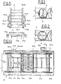
- the apparatus in question is placed downstream of a fruit orientating station, shown globally at SO, virtually constituted by a first endless chain 14 that is provided with continuous infeed motion in the direction of the arrow 61 and is equipped with a plurality of orientating means 13, each supporting one item of fruit, the orientation of all the fruit being in the same direction, that is to say, with the peduncular cavity pointing downwards and with the line of suture 4 thereof (see Figures 1 and 2) lying in a vertical plane perpendicular to the plane in Figure 3, with the most coloured part thereof pointing forwards.
- a fruit orientating station shown globally at SO, virtually constituted by a first endless chain 14 that is provided with continuous infeed motion in the direction of the arrow 61 and is equipped with a plurality of orientating means 13, each supporting one item of fruit, the orientation of all the fruit being in the same direction, that is to say, with the peduncular cavity pointing downwards and with the line of suture 4 thereof (see Figures 1 and 2) lying in a vertical plane per
- the said succession and orientation can be achieved manually or through an automatic apparatus designed for this purpose.
- the apparatus forming the subject of the invention is placed downstream, above the aforementioned station SO, and virtually consists of a plurality of carriages 29 drawn along an appropriate path constituted by an endless guide 36 with horizontal, bifurcations, that lies in the plane of Figure 3, by an endless chain 30 provided with uniform motion in time with that of the preceding fruit infeed chain 14, through a concatenation shown in the figure at 30'.
- the main drive MP is directly connected to the packing apparatus in question but operates the orientation station, that is to say, the chain 14, through a brake-clutch unit FF which is normally connected up, thereby keeping the two systems in phase, though it can be disconnected, as will be seen, in the case of infeed discontinuity.
- the chain 30 thus moves continuously, while the carriages 29 can be stopped, under the action of suitable halting means, in any position to form rows, one behind the other. In this way, with reference to Figure 4, it is possible to halt a certain number of carriages 29 in the waiting area shown at A.
- the first carriage is released from the area A and goes and takes the peach pres- ent, this being done under the action of a first releasing station shown at 33, while the opening and closing on to the peach of the gripper elements of the carriage is effected by corresponding devices shown globally at 34.
- a second halting station 35 or 35' stops the arriving carriages 29,'which thus go tightly one up against the other and form a row of growing length.
- the halting point of the first carriage and the pitch P of the compact row are such as to cause the position of the peaches to coincide with the underneath pockets of the suitably positioned tray 2.
- the station 35' staggered by half a pitch P with respect to the station 35 and placed on the opposite side thereto, attends to the halting of a second row of filled carriages.
- each carriage 29 is constituted by a body 29a provided transversely with a through pin 29e that has at the extremities thereof a pair of wheels/bearings 29c, at the back of which (with respect to the motion direction shown again at 61) there are two expansion members 29b, both the said wheels and the said expansion members being so placed as to create stable guide elements for the carriage 29 inside the two lateral guides 36 that follow the same path as the triple chain 30 from whose axis they maintain spacing that is constant.
- a sprocket 29d meshed constantly with the central link in the chain 30.
- the sprocket 29d is held tightly in between the said clutch drive elements constituted by two permanent magnets 29f, in such a way as to always be braked.
- the lower part of the body 29a houses what is really the -gripping element or device, constituted by two arms 29g, fixed to bushes 29h, in turn movable inside a horizontal transverse tubular element 291,drawn one towards the other through the action of a spring 29m.
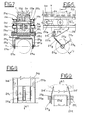
- the two arms which engage in a longitudinal slot machined bilaterally in the element 291, are provided, at the upper extremity thereof, with two needle rollers 29i that slide, following the.action of the carriages, on a cam 34' (see Figure 9) which constitutes the said opening and closing device 34.
- the two arms 29g are bent forward with nespect to the motion direction of the carriage 29, and the lower part of each is provided with a rubber pad 29n, connected to the arm 29g by a small ball bearing 29o, for bilaterally grasping the peach which is thus able to rotate around the horizontal centre of gravity axis v-v so that it may be given a definite "lying on one side" configuration.
- the system for controlling the motion or the halting of the peach carrying carriages is constituted by a cross 33c, placed horizontally at the side of the path followed by the carriages and free to rotate around a pin 33b, in turn integral with the support 33a that joins the station to the -frame of the apparatus.
- each arm of the cross 33c At the extremity of each arm of the cross 33c is mounted an idle roller 33d, of a suitable diameter, the pin 33b being so placed that the cross, during the rotatory motion thereof, hits the trajectory of the lateral tail pieces 29b of each carriage.
- each arriving carriage causes a quarter rotation of the cross 33c, without this in any way affecting the motion of the said carriage.
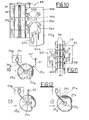
- the blocking of the carriage occurs through the interposition of the latch 33e under the action of an electromagnet 33f, or some other similar actuating means . If the magnet stays de-energized, that is to say, the cross 33c continues to be free to rotate, it is possible to cause whatever number wished of carriages (this applies to the stations 35 and 35') to transit freely. Should, instead, the electromagnet be excited by one single impulse and then be immediately released, only one carriage is able to transit; behind this is automatically repositioned a stop roller which, with the latch 33e having returned to the operative position, serves to block the following carriage and all the others there behind (this applies to the releasing station 33).
- assemblies 35 and 35' it can be said that they are identical to 33 and that they are placed ( Figure 11) on opposite sides to the carriage motion guide 36, for reasons of space.
- the position of one with respect to the other in the direction in which the carriages move forwards, is adjustable in such a way as to allow the inter-row staggering to be varied. Additionally, the position of the complete assembly can, in turn, be varied to suit the depositing necessities and the shape of the container.
- the assemblies 35 and 35' are operated alternately, as already described, in a sequence of operations that will be described in the ensuing text.
- the devices for opening and closing the elements that take hold of the peaches have, as previously stated, been shown at 34. More precisely, with reference to Figures 7 and 9, the said devices are constituted by a fixed cam 34', integral with the frame, that extends along the path of the guides 36 from the station 33 where the opening of the arms 29g takes place under the action of the rollers 29i (the major area of the cam 34 seen diagrammatically in- Figure 9), right along the area where the carriages move downwards, the profile of the cam continuing to be constant and the gripping elements in a continuously open configuration, until the region where possession is taken of the peach (shown at K in Figure 4) is reached, the profile decreasing there in a brusque fashion in order to allow the pads 29n, under the action of the spring 29m, to grasp the underneath peach.
- a fixed cam 34' integral with the frame, that extends along the path of the guides 36 from the station 33 where the opening of the arms 29g takes place under the action of the rollers 29i (the major area of the cam 34 seen
- Each filled carriage then passes over the lower bifurcation of the guides 36 until it arrives in the region of the aforementioned locator member 37, with the arms 29g displaced forwards in the configuration depicted in Figure 12a. Subsequently, through the lateral tail piece 29r integral with the pad 29n, it is possible to cause the pad to be displaced in the reverse direction to the motion, namely anti clockwise, with the consequent rotation of the peach around the centre of gravity axis v-v thereof and the definite "lying on one side" configuration ( Figures 12b and 12c) of the peach, the stable positioning of this being created by the constant abutment of the tail piece 29r on the arm 29g.
- the flexure rigidity of the locator member 37, to which is coupled a spring 37', is such as to allow the inflection thereof only when the tail piece 29r is able to offer a cer--tain resistance, that is to say, after rotation when the tail piece is resting on the arm 29g.
- the device 37 is dismantled and the peach is deposited in the configuration depicted in Figure 12a.
- the peaches have to be deposited and to this attends a second device for opening the gripping elements, shown globally at 39, placed along the path of the guides 36, in the region of the depositing area.
- This comprises a pair of "L" shaped bars 39a, the conformation of which is such that the arriving carriage 29 can move freely or halt in an open or closed position.
- the vertical edge 39c of each bar lies in between the side of the carriage and the innermost position adopted by the roller 29i.
- Each of the said bars is connected to two members 39b and 39c which, jointly with the frame T of the apparatus, constitute an articulated parallelogram whose operation is achieved through a pair of double acting pneumatic cylinders 39d that exert an effect on the extension to the member 39c and are pivoted to the frame T.
- the length of the bar 39a is such as to be able to exert, contemporaneously, an effect on all the carriages present in a depositing area, corresponding to the length of each container.
- the two bars 39a are returned outwards, this moving the rollers 29i of each carriage (arrow 39m in Figure 13), thereby causing the arms 29g to open and, in consequence, the fruit to drop into the underneath container.
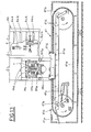
- the said station is composed of two parts, namely a magazine-cum-feeder 40 that is able to insert, each time it is required, a tray into the filling area (see Figures 13 and 5), and a drive group 41 (see Figures 13 and 14) capable -of supplying the said tray, coming from the preceding magazine, to the depositing area.
- the magazine-cum-feeder 40 placed vertically and supported at the sides by the frame T of the complete apparatus, serves to house the trays 2 that are manually stacked within the guides 40a thereof.
- the locking and releasing of each individual tray occurs through a system of control whereby the whole stack drops down by gravity.
- a first locking element 40b constituted by a catch pivoted to the guides 40a, by exerting an effect on the underneath of the tray under the action of the pneumatic cylinders 40c, prevents the trays placed in the magazine from freely dropping down, while a second locking element 40d, placed higher up allows, since it is open, the trays to arrive at the lower position.
- the element 40d is actuated and, through the elastic pads 40f, it applies a hold on the side of the penultimate tray, thereby blocking all those above.
- the element 40b see the configuration shown in dashes in Figure 5), it is possible to free only the last tray, which drops by gravity on to the underneath drive group 41.
- the element 40b is repositioned (the configuration shown in Figure 5 with a solid line) and then the upper element 40d is opened so as to allow the whole stack to move downwards and rest on the closed element 40b.
- an emergency signal from the device SMC takes the apparatus out of operation once the last container has been filled.
- the group for driving the said trays, or containers is constituted (see also Figure 14) by a roller support platform 41a on which the tray, dropping out of the feeder 40, rests.
- the said platform is connected to the framework of the complete drive group 41, through an articulated parallelogram system 41b operated by a pneumatic cylinder 41c, that causes the entire roller platform 41a to be raised or lowered.
- the latter is then placed beneath and inside the area occupied by the pair of drive chains 41e, parallel and endless, that connect such a number of idle pusher rollers 41d as to define, between one pusher and the next, a number of spaces in which a tray can be deposited.
- the said chains 41e are moved by a self-braking geared motor that always rotates in the same direction (anti-clockwise in Figure 13), corresponding to the direction needed to carry the trays into the depositing area.
- the said trays are made to drop out of the magazine at the very moment when a pusher 41d is timed to be positioned suitably, as will be seen, underneath the magazine.
- the movement of the chains, and thus of the trays, is intermittent so that the individual tray may move each time the filling of one row has been brought to an end, with a displacement perpendicular thereto, in such a way that there be, each time, an empty row under the depositing area. After each displacement, the tray pauses for the time required to deposit another row, and then moves off again once the filling has been completed.
- the tray has to be arranged in a way whereby the rows of aligned pockets be perpendicular to the movement direction, the extent of this being dependent upon the shape of the tray, the number of rows, the position in which the tray lies with respect to the borders, and the -distance in between two adjacent trays, etcetera.
- the system adopted to control these displacements is constituted by two cogged pulleys 41h, integral with the rivets of the chains 41e, which cause an endless cogged belt 41L to move, the outside of the latter having mounted thereon, either by gluing or some other method, a number of, suitably spaced, reflector plates (three sets, in the case under consideration).
- a first optical sensor 41m detects the presence of the first set T 1 of the said datum marks and, for each of them, operates in the region thereof the halting of the motor 41g and thus of the tray, the said datum marks being spaced apart at a distance identical to that in between two successive rows in one and the same tray or in two adjacent trays.
- the belt 41L can also be utilized to memorize other data too : for example, regarding the nature of the row, namely whether it has to have one item of fruit less than the others and, consequently, it may be necessary to override the operation of the halting station 35 or 35', etcetera; data of this nature can be detected by a second sensor 41n on the second set of plates T 2 .
- the traction system is identical to a step-by-step system : upon completion of one operation (the depositing operation, for example), the motor 41g is set in operation until the subsequent T 1 datum mark makes itself seen and causes the halting thereof. This, in turn, causes a fresh depositing operation, upon completion of which the system starts up again, and so on and so forth.
- the tray When each moving operation has ended, the tray is raised, in a standstill position, in such a way as to partially engage the peach in the pocket in the container thereof, this being to prevent any tendency to overturn during the releasing stage, which would jeopardize the final result. Similarly, the tray has to be back in the down position at the commencement of the subsequent displacement, in order not to bit the trajectory of the gripping elements 29g when the motion is resumed and, above all, in the changeover from a filled tray to the subsequent empty tray.
- the main motor MP is directly connected to the chain 30 (via the connection 30'), while it operates the orientation station SO, that is to say, the chain 14, via the unit FF.
- the clutch is normally engaged and thus the START-STOP control operates both chains of the apparatus.
- FIGs 16 and 17 is illustrated the group C 3 which can be subdivided into three sub-groups C 3 /1, C 3/2 and C 3/3 .
- the first of these comprises the tray advancement motor 41g which is set in motion either through a manual starter AM or the contemporaneous presence of the two signals ⁇ RIL and ⁇ DEP, mention of which will also be made hereinafter.
- the blocks marked with the letter Q are "AND" elements, whilst those marked with the letter R are “OR” elements.
- the sensor 41mm detects the datum marks on a third set T 3 provided on the belt 41L, which are spaced one away from the other at a distance equal to the width of one tray.
- the said signals cause the chain 41e to come to a halt in a way in which the pushers 41d are in the precise position . to receive a tray dropping out of the magazine 40.
- the sensor 41nn checks the presence of the tray in the depositing area and, should there not be one, invalidates the signals of the other two sensors 41m and 41n but not that of the sensor 41mm; in fact, in this instance the motor 41g only halts the chain in the region of a T 3 datum mark up until the time when a tray is present in the depositing area (actuation of the sensor 41nn); just as soon as a tray does drop down, the sensor 41nn reinstates the signal of the sensor 41m, which halts the chain in the region of each of the datum marks T 1 of the first row that determine the correct positioning for the release of the peaches.
- the sensor 41n When everything starts up again after each pause (always when there is a tray present), the sensor 41n is informed by the datum mark T 2 , eventually present in the second row, whether the next row of peaches is, to be a long or short one: this information is transferred to the counting and releasing sub-group C 3/2.
- the latter is constituted by two optical sensors SCPu and SCPi, the first of which counts the carriages leaving the depositing area after the depositing operation has taken place, and the second of which counts the filled carriages entering the said area, that have to be blocked for the subsequent depositing of one complete row; by two pairs of counting means ⁇ ' K, ⁇ 'J, and ⁇ k, ⁇ J having preselected value possibilities, the consent to each pair being given by SCP U and SCPi, respectively;-and by the two electromagnets 35f and 35'f that belong to the stations 35 and 35 1 , respectively (see Figure 17).
- Each of the said sensors detects the passing of the transiting carriages, the number of which is totalled by both the counting means (preselected at different values for the pockets in two consecutive rows) but only one of them is taken into consideration each time, this depending on whether or not, during the positioning of the tray 2, the datum mark T 2 was present (the short row detected by the sensor 41n), this latter being a SET signal from the flip-flop Z controlled by the signal detected by the sensor 41n.
- the sensor SCPu is utilized for the blocking of the stations 35 and 35', so is the sensor SCPi for the device that opens the gripping elements once the predetermined value has been reached.
- the group C 3/3 is constituted by a pneumatic cylinder 41c that raises the tray in order to bring it close to the peaches, and by the pair of cylinders 39d for opening the arms 29g.
- the said cylinders are connected to a logic pneumatic circuit CP 3/3 that is independent and attends to the following sequence of operations, namely : the raising of the platform, the opening and closing of the arms, and the lowering of the platform.
- the consent signal ⁇ -DEP is given when the following has occurred: the chain has placed the tray in position (41m-41nn); the counting means ⁇ J or ⁇ K have signalled the presence of the row of peaches and the corresponding station 35 or 35' has blocked them in position.
- the signal from the sensor 41n prepares the counting means for the formation of a fresh row.
- the group C 4 which has as actuator devices the two pneumatic cylinders 4Cc and 40e, the operational sequence of which has been previously described, is controlled by a logic-pneumatic circuit CP 4 activated by the presence of the consent signal ⁇ RIL generated by the following condition having occurred : teh chain 41e at a standstill in the correct tray release position (signal from the sensor 41mm, see group C 3/1 ) this necessitating there being trays in the magazine 40 (sensor SMC).
- the circuit CP 4 When the said cycle has ended, that is to say, with a fresh tray being released, the circuit CP 4 generates a consent signal ⁇ - RIL for the actuation of the groups and of the subsequent operations.
- the invention can also adopt forms that differ from what has been described above and, in particular, numerous modifications of a practical nature may be made without this, in any way, deviating from the framework of protection afforded thereto.
Landscapes
- Life Sciences & Earth Sciences (AREA)
- Agronomy & Crop Science (AREA)
- Engineering & Computer Science (AREA)
- Mechanical Engineering (AREA)
- Container Filling Or Packaging Operations (AREA)
- Packaging Of Special Articles (AREA)
Applications Claiming Priority (2)
| Application Number | Priority Date | Filing Date | Title |
|---|---|---|---|
| IT03310/81A IT1194964B (it) | 1981-01-20 | 1981-01-20 | Appatecchiatura per la presa e per il confezionamento automatico di frutti,particolarmente pesche,alimentati in successione e provenienti da una stazione di orientamento concorde delgi stessi |
| IT331081 | 1981-01-20 |
Publications (2)
| Publication Number | Publication Date |
|---|---|
| EP0062007A2 true EP0062007A2 (fr) | 1982-10-06 |
| EP0062007A3 EP0062007A3 (fr) | 1983-03-16 |
Family
ID=11104726
Family Applications (1)
| Application Number | Title | Priority Date | Filing Date |
|---|---|---|---|
| EP82830002A Withdrawn EP0062007A3 (fr) | 1981-01-20 | 1982-01-05 | Dispositif pour emballer automatiquement des fruits |
Country Status (4)
| Country | Link |
|---|---|
| EP (1) | EP0062007A3 (fr) |
| ES (1) | ES8300613A1 (fr) |
| GR (1) | GR75113B (fr) |
| IT (1) | IT1194964B (fr) |
Cited By (3)
| Publication number | Priority date | Publication date | Assignee | Title |
|---|---|---|---|---|
| EP0727355A1 (fr) * | 1995-02-16 | 1996-08-21 | De Greef's Wagen- Carrosserie- en Machinebouw B.V. | Procédé et appareil pour emballer des produits d'agriculture et d'horticulture |
| WO1997042112A1 (fr) | 1996-05-07 | 1997-11-13 | De Greef's Wagen-, Carrosserie- En Machinebouw B.V. | Procede et dispositif d'amenee, de decharge et de transfert d'objets tels que des fruits |
| WO2024217028A1 (fr) * | 2023-04-19 | 2024-10-24 | 淮北师范大学 | Machine d'emballage de melons |
Families Citing this family (1)
| Publication number | Priority date | Publication date | Assignee | Title |
|---|---|---|---|---|
| CN109178379B (zh) * | 2018-08-31 | 2024-05-03 | 杭州量益科技有限公司 | 轴承装箱装置 |
Family Cites Families (3)
| Publication number | Priority date | Publication date | Assignee | Title |
|---|---|---|---|---|
| US3169354A (en) * | 1962-05-01 | 1965-02-16 | Page Detroit Inc | Egg handling and packing system |
| US3342012A (en) * | 1964-02-12 | 1967-09-19 | Barker Poultry Equipment Compa | Egg packer |
| US3590551A (en) * | 1969-03-27 | 1971-07-06 | Sunkist Growers Inc | Automatic apparatus for packing articles in boxes |
-
1981
- 1981-01-20 IT IT03310/81A patent/IT1194964B/it active
- 1981-10-29 GR GR67032A patent/GR75113B/el unknown
-
1982
- 1982-01-05 EP EP82830002A patent/EP0062007A3/fr not_active Withdrawn
- 1982-01-14 ES ES508748A patent/ES8300613A1/es not_active Expired
Cited By (5)
| Publication number | Priority date | Publication date | Assignee | Title |
|---|---|---|---|---|
| EP0727355A1 (fr) * | 1995-02-16 | 1996-08-21 | De Greef's Wagen- Carrosserie- en Machinebouw B.V. | Procédé et appareil pour emballer des produits d'agriculture et d'horticulture |
| NL9500296A (nl) * | 1995-02-16 | 1996-10-01 | Greefs Wagen Carrosserie | Werkwijze en inrichting voor het verpakken van land- en tuinbouwprodukten. |
| US5737901A (en) * | 1995-02-16 | 1998-04-14 | De Greef's Wagen-, Carrosserie-En Machinebouw, B.V. | Method and apparatus for packaging agricultural and horticultural produce |
| WO1997042112A1 (fr) | 1996-05-07 | 1997-11-13 | De Greef's Wagen-, Carrosserie- En Machinebouw B.V. | Procede et dispositif d'amenee, de decharge et de transfert d'objets tels que des fruits |
| WO2024217028A1 (fr) * | 2023-04-19 | 2024-10-24 | 淮北师范大学 | Machine d'emballage de melons |
Also Published As
| Publication number | Publication date |
|---|---|
| IT8103310A0 (it) | 1981-01-20 |
| ES508748A0 (es) | 1982-11-01 |
| IT1194964B (it) | 1988-09-28 |
| GR75113B (fr) | 1984-07-13 |
| ES8300613A1 (es) | 1982-11-01 |
| EP0062007A3 (fr) | 1983-03-16 |
Similar Documents
| Publication | Publication Date | Title |
|---|---|---|
| CA2015840C (fr) | Machine a emballer automatique modulaire | |
| US3641735A (en) | Bag packer with horizontal transfer | |
| EP1318089B1 (fr) | Dispositif de transport pour transférer en lots des articles disposés sur la tranche | |
| US4226073A (en) | Tray loader | |
| EP0305896B1 (fr) | Procédé pour positionner des bâtonnets dans des barquettes et dispositif pour la mise en oeuvre du procédé | |
| US4505373A (en) | Egg transfer system | |
| US4478024A (en) | Stack handling method and apparatus | |
| JPH06211213A (ja) | 物品処理方法および装置 | |
| EP0598397B1 (fr) | Unité de déchargement d'un convoyeur et méthode de déchargement à partir d'un convoyeur | |
| US3527337A (en) | Article pusher mechanism for bagging machines | |
| JPH04367417A (ja) | 包装機への物品の自動整列供給方法と装置 | |
| US5911553A (en) | Automatic wicketing apparatus | |
| US4616745A (en) | Apparatus for aligning and feeding articles upright on an article loading machine | |
| EP0062007A2 (fr) | Dispositif pour emballer automatiquement des fruits | |
| EP0512651A1 (fr) | Appareil pour recevoir ou transférer, transporter verticalement et délivrer des articles, comme des oeufs | |
| EP2560882B1 (fr) | Appareil et procédé d'alimentation en oeufs, par exemple, appareil et procédé permettant de remplir des plateaux à oeufs | |
| US4374559A (en) | Apparatus for handling articles | |
| US3973667A (en) | Apparatus for vertically transporting eggs or like articles | |
| DE2533780C3 (de) | Vorrichtung zum Füllen von Einsätzen für Verkaufsschachteln mit verschiedenartigen Gegenständen, insbesondere Pralinen | |
| US2634874A (en) | Shipping case unloading apparatus | |
| US2980231A (en) | Automatic switching and storage conveyor | |
| US5522690A (en) | Automatic wicketting apparatus | |
| US2842912A (en) | Article packing apparatus | |
| JPS5824332B2 (ja) | 物品の自動整列供給方法 | |
| US6351926B1 (en) | Packaging system |
Legal Events
| Date | Code | Title | Description |
|---|---|---|---|
| PUAI | Public reference made under article 153(3) epc to a published international application that has entered the european phase |
Free format text: ORIGINAL CODE: 0009012 |
|
| AK | Designated contracting states |
Designated state(s): DE FR GB |
|
| PUAL | Search report despatched |
Free format text: ORIGINAL CODE: 0009013 |
|
| AK | Designated contracting states |
Designated state(s): DE FR GB |
|
| STAA | Information on the status of an ep patent application or granted ep patent |
Free format text: STATUS: THE APPLICATION IS DEEMED TO BE WITHDRAWN |
|
| 18D | Application deemed to be withdrawn |
Effective date: 19840223 |
|
| RIN1 | Information on inventor provided before grant (corrected) |
Inventor name: VASSURA, GABRIELE |