EP0061928A1 - Vehicle rear shelf arrangement - Google Patents
Vehicle rear shelf arrangement Download PDFInfo
- Publication number
- EP0061928A1 EP0061928A1 EP19820301666 EP82301666A EP0061928A1 EP 0061928 A1 EP0061928 A1 EP 0061928A1 EP 19820301666 EP19820301666 EP 19820301666 EP 82301666 A EP82301666 A EP 82301666A EP 0061928 A1 EP0061928 A1 EP 0061928A1
- Authority
- EP
- European Patent Office
- Prior art keywords
- shelf
- vehicle
- tether
- door
- rear door
- Prior art date
- Legal status (The legal status is an assumption and is not a legal conclusion. Google has not performed a legal analysis and makes no representation as to the accuracy of the status listed.)
- Granted
Links
Images

Classifications
-
- B—PERFORMING OPERATIONS; TRANSPORTING
- B60—VEHICLES IN GENERAL
- B60R—VEHICLES, VEHICLE FITTINGS, OR VEHICLE PARTS, NOT OTHERWISE PROVIDED FOR
- B60R5/00—Compartments within vehicle body primarily intended or sufficiently spacious for trunks, suit-cases, or the like
- B60R5/04—Compartments within vehicle body primarily intended or sufficiently spacious for trunks, suit-cases, or the like arranged at rear of vehicle
- B60R5/044—Compartments within vehicle body primarily intended or sufficiently spacious for trunks, suit-cases, or the like arranged at rear of vehicle luggage covering means, e.g. parcel shelves
- B60R5/045—Compartments within vehicle body primarily intended or sufficiently spacious for trunks, suit-cases, or the like arranged at rear of vehicle luggage covering means, e.g. parcel shelves collapsible or transformable
Definitions
- This invention relates to vehicles of the type having a rear door hinged at the top thereof to the vehicle body and a seat in front of the rear door, wherein a shelf between the seat and the door is hinged adjacent the front of the shelf and is connected by a tether to the door so that the shelf is hinged upwardly in response to opening of the door.
- a tether is connected at one end to the shelf and at the other end to the door.
- a vehicle having a rear door hinged at the top thereof to the vehicle body, a seat in front of the rear door, a shelf between the seat and the door hinged along or adjacent the front of the shelf and a tether extending between the shelf and the door to pivot the shelf upwardly in response to opening of the rear door characterised in that at least one guide is mounted on the door above the shelf and the tether extending from the shelf behind the . shelf hinge and around the guide and being anchored to a part of the vehicle below the door hinge.
- the guidein the present invention can be located nearer the door hinge that the point of attachment of the tether to the door in the known arrangement described above, to obtain the same amount of lift of the shelf as in the known arrangement, and consequently the tension in the tether when the door is open is less than in the known arrangement.
- the guide can be arranged to provide more lift of the shelf than in the known arrangement described above without increasing the maximum tension in the tether.
- a motor vehicle has an upwardly pivotabLe rear door 10 incorporating a backlight 11 which extends substantially the width and length of the door.
- the door is provided with conventional gas struts or torsion springs (not shown) to hold the door open.
- a parcel tray/ luggage cover comprising a shelf 12 extends horizontally between the rear of a forwardly tiltable rear seat backrest 13 towards the door and above the level of the lower edge of the backlight 11.
- the front edge of the shelf is pivotably connected at 14 to spaced apart brackets 15 secured to the rear of the rear seat backrest 13 whilst the side edges of the shelf rest upon support elements (not shown) formed by interior trim panels or on part of the vehicle body side structure.
- Holes 16 are formed in the shelf 12 adjacent the rear corners thereof.' A respective flexible cord 17 passes through each hole 16 on the respective side of the shelf as shown in Figure 2 to form an upwardly extending loop on each side thereof which passes over a flanged pulley 18 rotatably mounted on a bracket 19 secured to the underside of the side frame of the door 10 as shown in Figure 1.
- a reinforcing element 21 is secured to the shelf 12 along the rear edge therof and comprises a U-section portion 22 which engages around the rear edge of the shelf and an arcuate section portion 23 extending along the marginal underside rear edge of the shelf to form a conduit therewith and with which the holes 16 in the rear corners of the shelf 12 are in communication.
- the end of each flexible cord 17 below the shelf 12 extends beyond the stop member 20 and is connected to one end of a respective suitably - tensioned elastic cord 24, The elastic cords 24 extend along said conduit in side-by-side relationship and are secured at their opposite ends to the wall of the arcuate - section portion 23 of the reinforcing element 21 as shown for example in Figure 3.
- a relatively narrow panel 25 extending the width of the shelf 12 and underlaying the marginal lower edge of the backlight 11 is pivotably attached at its lower rear edge 26 to the underside of the frame of the rear door 10 and extends upwardly parallel to it.
- the upper forward marginal edge 27- of the panel 25 is formed at an angle thereto such that in the closed position of the rear door it extends horizontally forwardly to slightly overlay the rear edge of shelf 12, thus obturating the space between the rear of shelf 12 and the underside of the door 10.
- the panel 25 is normally held in the parallel position against the door 10 by suitable resilient snap-connection means (not shown) at each end of the panel, but may be released therefrom for pivotable movement away from the door for the purpose of cleaning the area of backlight which it underlays.
- the cords 17 extend forwardly as they extend upwardly from the rear edge of the shelf 12 to the pulleys 18.
- the angle A between those portions of the cords 17 and the shelf 12 is short of 180°, being about 140° to 150°, and so there is little tendency for the cords 17 to limit the fully open position of the door 10 or for the door 10 in the fully open position to overstress the cords 17 or rip the shelf 12 from its hinge 14.
- the shelf 12 When the shelf 12 is not needed it can be stowed behind the rear seat backrest by first disconnecting the cords 17 from the pulleys 18 such that the cords are retracted to fit neatly along the upper surface of shelf 12 by the action of the elastic cords 24 described above.
- the rear seat backrest is then tilted forwardly to enable the sides of the shelf 12 to clear the shelf support elements and permit the shelf to be pivoted downwardly against the rear face of the backrest which can be tilted fully forwardly to a substantially horizontal position or returned to its normal substantially upright position with the shelf stowed against it as shown in dotted line in Figure 1.
- the pivots 14 and brackets 15 may be spaced apart on one of the backrest portions thus permitting the other backrest portion to be tilted forwardly to an out of use position without disturbing said one of the backrest portions.
- the pivotable panel 25 and associated snap connections may be replaced by a dense opaque band along the marginal lower edge of the backlight and on the underside thereof to provide a means for masking the gap between the rear edge of the shelf 12 and the backlight 11 to prevent visual inspection of the luggage stowage space 28:
- the band may be secured to the underside surface of the backlight or form an integral part thereof.
- the arrangements described hereinbefore are particularly suitable for increasing the available volume of luggage stowage space and the access thereto without alteration to an existing backlight area or rear door structure.
- the height of the backlight 11 may be reduced and the corresponding lower portion of the rear door frame below the backlight widened accordingly, such that, with an increased length of shelf 12, the wider lower portion of the door frame is just above the level of shelf 12 and prevents visual viewing of the luggage space 28.
- both the panel 25 and its associated snap-connections or the alternative opaque band on the backlight can be eliminated.
Abstract
Description
- This invention relates to vehicles of the type having a rear door hinged at the top thereof to the vehicle body and a seat in front of the rear door, wherein a shelf between the seat and the door is hinged adjacent the front of the shelf and is connected by a tether to the door so that the shelf is hinged upwardly in response to opening of the door.
- In a known arrangement in which the door pivots from a closed, downwardly inclined position to an open, upwardly inclined position and the shelf hinge is disposed below the door hinge, a tether is connected at one end to the shelf and at the other end to the door. With such an arrangement, the amount by which the shelf can be pivoted upwardly when the door is opened is limited by the tether becoming aligned with the shelf, and as the tether approaches alignment with the shelf, the tension in the tether increases.
- In accordance with the present invention, there is provided a vehicle having a rear door hinged at the top thereof to the vehicle body, a seat in front of the rear door, a shelf between the seat and the door hinged along or adjacent the front of the shelf and a tether extending between the shelf and the door to pivot the shelf upwardly in response to opening of the rear door characterised in that at least one guide is mounted on the door above the shelf and the tether extending from the shelf behind the . shelf hinge and around the guide and being anchored to a part of the vehicle below the door hinge..
- The guidein the present invention can be located nearer the door hinge that the point of attachment of the tether to the door in the known arrangement described above, to obtain the same amount of lift of the shelf as in the known arrangement, and consequently the tension in the tether when the door is open is less than in the known arrangement. Alternatively, the guide can be arranged to provide more lift of the shelf than in the known arrangement described above without increasing the maximum tension in the tether.
- A specific embodiment of the invention and modifications thereof will now be described by way of example reference being made to the accompanying drawings, in which:
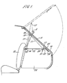
- Figure 1 is a diagrammatic sectional view in side elevation showing the rear portion of the vehicle according to one embodiment of the invention;
- Figure 2 is a diagrammatic perspective view of part of the embodiment shown in Figure 1; and
- Figure 3 is a perspective cut-away and part "exploded" view of part of the embodiment shown in Figure 1.
- Referring to the drawings, a motor vehicle has an upwardly pivotabLe
rear door 10 incorporating abacklight 11 which extends substantially the width and length of the door. The door is provided with conventional gas struts or torsion springs (not shown) to hold the door open. In the closed position of the door, a parcel tray/ luggage cover comprising ashelf 12 extends horizontally between the rear of a forwardly tiltablerear seat backrest 13 towards the door and above the level of the lower edge of thebacklight 11. - The front edge of the shelf is pivotably connected at 14 to spaced apart
brackets 15 secured to the rear of therear seat backrest 13 whilst the side edges of the shelf rest upon support elements (not shown) formed by interior trim panels or on part of the vehicle body side structure. -
Holes 16 are formed in theshelf 12 adjacent the rear corners thereof.' A respectiveflexible cord 17 passes through eachhole 16 on the respective side of the shelf as shown in Figure 2 to form an upwardly extending loop on each side thereof which passes over a flangedpulley 18 rotatably mounted on abracket 19 secured to the underside of the side frame of thedoor 10 as shown in Figure 1. Astop member 20, which can alternatively be a suitable knot, is provided on that end of eachflexible cord 17, below theshelf 12 to abut the underside of the shelf to prevent the ccrds from being pulled upwardly through theholes 16. - A reinforcing
element 21 is secured to theshelf 12 along the rear edge therof and comprises aU-section portion 22 which engages around the rear edge of the shelf and anarcuate section portion 23 extending along the marginal underside rear edge of the shelf to form a conduit therewith and with which theholes 16 in the rear corners of theshelf 12 are in communication. For a purpose to be described later, the end of eachflexible cord 17 below theshelf 12 extends beyond thestop member 20 and is connected to one end of a respective suitably - tensionedelastic cord 24, Theelastic cords 24 extend along said conduit in side-by-side relationship and are secured at their opposite ends to the wall of the arcuate -section portion 23 of the reinforcingelement 21 as shown for example in Figure 3. - A relatively
narrow panel 25 extending the width of theshelf 12 and underlaying the marginal lower edge of thebacklight 11 is pivotably attached at its lowerrear edge 26 to the underside of the frame of therear door 10 and extends upwardly parallel to it. The upper forward marginal edge 27- of thepanel 25 is formed at an angle thereto such that in the closed position of the rear door it extends horizontally forwardly to slightly overlay the rear edge ofshelf 12, thus obturating the space between the rear ofshelf 12 and the underside of thedoor 10. Thepanel 25 is normally held in the parallel position against thedoor 10 by suitable resilient snap-connection means (not shown) at each end of the panel, but may be released therefrom for pivotable movement away from the door for the purpose of cleaning the area of backlight which it underlays. - Referring to Figure 1, when the
rear door 10 is pivoted upwardly from the closed position shown in full line to the open position shown in chain-dotted line thepanel 25 moves with the door away fromshelf 12. Simultaneously,shelf 12 pivots upwardly aboutpoint 14 by movement of thepulleys 18 along the respective loops ofcords 17 to the position also shown in chain-dotted line, the arrangement thus providing a large angle of pivotable movement of theshelf 12 with good access to the luggage stowage space 28. It will be noted that the width of the rear part of theshelf 12 must be such that it can pass through the aperture for therear door 10. - In both positions of the
shelf 12, as shown in full line and chain-dotted line in Figure 1, thecords 17 extend forwardly as they extend upwardly from the rear edge of theshelf 12 to thepulleys 18. In the upper position the angle A between those portions of thecords 17 and theshelf 12 is short of 180°, being about 140° to 150°, and so there is little tendency for thecords 17 to limit the fully open position of thedoor 10 or for thedoor 10 in the fully open position to overstress thecords 17 or rip theshelf 12 from itshinge 14. - When the
shelf 12 is not needed it can be stowed behind the rear seat backrest by first disconnecting thecords 17 from thepulleys 18 such that the cords are retracted to fit neatly along the upper surface ofshelf 12 by the action of theelastic cords 24 described above. The rear seat backrest is then tilted forwardly to enable the sides of theshelf 12 to clear the shelf support elements and permit the shelf to be pivoted downwardly against the rear face of the backrest which can be tilted fully forwardly to a substantially horizontal position or returned to its normal substantially upright position with the shelf stowed against it as shown in dotted line in Figure 1. Ir- the case where the rear seat backrest comprises two independently pivotable portions thepivots 14 andbrackets 15 may be spaced apart on one of the backrest portions thus permitting the other backrest portion to be tilted forwardly to an out of use position without disturbing said one of the backrest portions. - In an alternative embodiment, the
pivotable panel 25 and associated snap connections may be replaced by a dense opaque band along the marginal lower edge of the backlight and on the underside thereof to provide a means for masking the gap between the rear edge of theshelf 12 and thebacklight 11 to prevent visual inspection of the luggage stowage space 28: The band may be secured to the underside surface of the backlight or form an integral part thereof. - It will be appreciated that the arrangements described hereinbefore are particularly suitable for increasing the available volume of luggage stowage space and the access thereto without alteration to an existing backlight area or rear door structure. In other cases and where desired, the height of the
backlight 11 may be reduced and the corresponding lower portion of the rear door frame below the backlight widened accordingly, such that, with an increased length ofshelf 12, the wider lower portion of the door frame is just above the level ofshelf 12 and prevents visual viewing of the luggage space 28. By this means, both thepanel 25 and its associated snap-connections or the alternative opaque band on the backlight can be eliminated.
Claims (16)
Applications Claiming Priority (2)
| Application Number | Priority Date | Filing Date | Title |
|---|---|---|---|
| GB8110094 | 1981-03-31 | ||
| GB8110094A GB2095627B (en) | 1981-03-31 | 1981-03-31 | Vehicle rear shelf arrangement |
Publications (2)
| Publication Number | Publication Date |
|---|---|
| EP0061928A1 true EP0061928A1 (en) | 1982-10-06 |
| EP0061928B1 EP0061928B1 (en) | 1986-02-26 |
Family
ID=10520810
Family Applications (1)
| Application Number | Title | Priority Date | Filing Date |
|---|---|---|---|
| EP19820301666 Expired EP0061928B1 (en) | 1981-03-31 | 1982-03-30 | Vehicle rear shelf arrangement |
Country Status (3)
| Country | Link |
|---|---|
| EP (1) | EP0061928B1 (en) |
| DE (1) | DE3269288D1 (en) |
| GB (1) | GB2095627B (en) |
Cited By (7)
| Publication number | Priority date | Publication date | Assignee | Title |
|---|---|---|---|---|
| FR2687963A1 (en) * | 1992-02-28 | 1993-09-03 | Treves Ets | Guide members for the two retractable cords joined to the hatch door (tailgate) of a car |
| WO1999030927A1 (en) * | 1997-12-18 | 1999-06-24 | Lear Corporation | Interlocking rear seat and package tray assembly |
| US6113172A (en) * | 1998-12-22 | 2000-09-05 | Daimlerchrysler Corporation | Multi-positional vehicle shelf |
| DE19711818B4 (en) * | 1996-03-30 | 2004-09-23 | Volkswagen Ag | Motor vehicle with a rear door which can be pivoted upwards when opened |
| FR2932741A1 (en) * | 2008-06-24 | 2009-12-25 | Peugeot Citroen Automobiles Sa | DEVICE FOR TRAPPING A REAR SHELF OF A MOTOR VEHICLE, BY DRIVING INTO ROTATION AND TRANSLATION |
| CN102009621A (en) * | 2009-09-08 | 2011-04-13 | 本田技研工业株式会社 | Parcel shelf structure |
| US9987990B1 (en) * | 2016-11-30 | 2018-06-05 | Nissan North America, Inc. | Vehicle rear cargo area structure |
Families Citing this family (2)
| Publication number | Priority date | Publication date | Assignee | Title |
|---|---|---|---|---|
| US4728141A (en) * | 1985-05-31 | 1988-03-01 | Honda Giken Kogyo Kabushiki Kaisha | Automotive rear shelf structure |
| EP4129770B1 (en) * | 2020-05-25 | 2024-02-28 | Zhejiang Liankong Technologies Co., Ltd | Vehicle back door |
Citations (3)
| Publication number | Priority date | Publication date | Assignee | Title |
|---|---|---|---|---|
| GB1456747A (en) * | 1973-03-20 | 1976-11-24 | Renault | Arrangement for raising a hinged shelf arranged over a space accessible through a rear door of a motor vehicle |
| GB1459056A (en) * | 1973-12-28 | 1976-12-22 | Renault | Arrangement for raising a movable tray of the read luggage compartment in a motor vehicle |
| GB2040833A (en) * | 1979-01-16 | 1980-09-03 | Nissan Motor | Vehicle luggage compartment cover apparatus |
-
1981
- 1981-03-31 GB GB8110094A patent/GB2095627B/en not_active Expired
-
1982
- 1982-03-30 DE DE8282301666T patent/DE3269288D1/en not_active Expired
- 1982-03-30 EP EP19820301666 patent/EP0061928B1/en not_active Expired
Patent Citations (3)
| Publication number | Priority date | Publication date | Assignee | Title |
|---|---|---|---|---|
| GB1456747A (en) * | 1973-03-20 | 1976-11-24 | Renault | Arrangement for raising a hinged shelf arranged over a space accessible through a rear door of a motor vehicle |
| GB1459056A (en) * | 1973-12-28 | 1976-12-22 | Renault | Arrangement for raising a movable tray of the read luggage compartment in a motor vehicle |
| GB2040833A (en) * | 1979-01-16 | 1980-09-03 | Nissan Motor | Vehicle luggage compartment cover apparatus |
Cited By (12)
| Publication number | Priority date | Publication date | Assignee | Title |
|---|---|---|---|---|
| FR2687963A1 (en) * | 1992-02-28 | 1993-09-03 | Treves Ets | Guide members for the two retractable cords joined to the hatch door (tailgate) of a car |
| DE19711818B4 (en) * | 1996-03-30 | 2004-09-23 | Volkswagen Ag | Motor vehicle with a rear door which can be pivoted upwards when opened |
| WO1999030927A1 (en) * | 1997-12-18 | 1999-06-24 | Lear Corporation | Interlocking rear seat and package tray assembly |
| GB2347390A (en) * | 1997-12-18 | 2000-09-06 | Lear Corp | Interlocking rear seat and package tray assembly |
| GB2347390B (en) * | 1997-12-18 | 2002-03-20 | Lear Corp | Interlocking rear seat and package tray assembly |
| US6113172A (en) * | 1998-12-22 | 2000-09-05 | Daimlerchrysler Corporation | Multi-positional vehicle shelf |
| US6176535B1 (en) * | 1998-12-22 | 2001-01-23 | Daimlerchrysler Corporation | Multi-positional vehicle shelf |
| FR2932741A1 (en) * | 2008-06-24 | 2009-12-25 | Peugeot Citroen Automobiles Sa | DEVICE FOR TRAPPING A REAR SHELF OF A MOTOR VEHICLE, BY DRIVING INTO ROTATION AND TRANSLATION |
| EP2138353A1 (en) * | 2008-06-24 | 2009-12-30 | Peugeot Citroen Automobiles SA | Device for folding away a rear shelf of an automobile, by rotation and translation |
| CN102009621A (en) * | 2009-09-08 | 2011-04-13 | 本田技研工业株式会社 | Parcel shelf structure |
| US8172296B2 (en) * | 2009-09-08 | 2012-05-08 | Honda Motor Co., Ltd. | Parcel shelf structure |
| US9987990B1 (en) * | 2016-11-30 | 2018-06-05 | Nissan North America, Inc. | Vehicle rear cargo area structure |
Also Published As
| Publication number | Publication date |
|---|---|
| DE3269288D1 (en) | 1986-04-03 |
| GB2095627A (en) | 1982-10-06 |
| EP0061928B1 (en) | 1986-02-26 |
| GB2095627B (en) | 1984-04-18 |
Similar Documents
| Publication | Publication Date | Title |
|---|---|---|
| US5211718A (en) | Convertible with a wind-deflecting cover | |
| EP1547870B1 (en) | Vehicle side panel storage box assembly | |
| US4202577A (en) | Motor vehicle provided with a hatch-back door closing off a storage space | |
| US5716091A (en) | Flipper panel with storage bin | |
| US5810413A (en) | Storage device | |
| US6719343B2 (en) | Vehicle console assembly | |
| US5535931A (en) | Storage system | |
| EP0233777B1 (en) | Open-top vehicle body | |
| US5944378A (en) | Two-part convertible top for a motor vehicle | |
| EP0365175B1 (en) | A seat assembly for a vehicle | |
| EP0061928B1 (en) | Vehicle rear shelf arrangement | |
| US6267427B1 (en) | Truck bed divider | |
| EP0348130A2 (en) | Safety arrangement for overhead luggage bins in aircraft passenger cabins | |
| WO1999003718A1 (en) | Adaptable pick up truck configuration | |
| EP2078636B1 (en) | Improvements in or relating to in-vehicle luggage systems | |
| US4275917A (en) | Auxiliary visor | |
| WO2004020245A2 (en) | Vehicle cargo panel having retractable belt | |
| US4363512A (en) | Auxiliary visor | |
| US4131293A (en) | Retractable service ladder | |
| US6312036B1 (en) | Cargo space covering or hat holding piece with movable corner pieces | |
| US4040501A (en) | Lift truck | |
| EP0553572B1 (en) | Motor vehicles | |
| EP1439093B1 (en) | Vehicle parcel shelf | |
| US5054846A (en) | Folding glass sunroof | |
| US6779837B1 (en) | Mesh side shield for vehicle sunroof |
Legal Events
| Date | Code | Title | Description |
|---|---|---|---|
| PUAI | Public reference made under article 153(3) epc to a published international application that has entered the european phase |
Free format text: ORIGINAL CODE: 0009012 |
|
| AK | Designated contracting states |
Designated state(s): DE FR IT |
|
| 17P | Request for examination filed |
Effective date: 19830405 |
|
| GRAA | (expected) grant |
Free format text: ORIGINAL CODE: 0009210 |
|
| ITF | It: translation for a ep patent filed |
Owner name: BARZANO' E ZANARDO ROMA S.P.A. |
|
| AK | Designated contracting states |
Designated state(s): DE FR IT |
|
| REF | Corresponds to: |
Ref document number: 3269288 Country of ref document: DE Date of ref document: 19860403 |
|
| ET | Fr: translation filed | ||
| PLBE | No opposition filed within time limit |
Free format text: ORIGINAL CODE: 0009261 |
|
| STAA | Information on the status of an ep patent application or granted ep patent |
Free format text: STATUS: NO OPPOSITION FILED WITHIN TIME LIMIT |
|
| 26N | No opposition filed | ||
| ITTA | It: last paid annual fee | ||
| PGFP | Annual fee paid to national office [announced via postgrant information from national office to epo] |
Ref country code: FR Payment date: 19920320 Year of fee payment: 11 |
|
| PGFP | Annual fee paid to national office [announced via postgrant information from national office to epo] |
Ref country code: DE Payment date: 19920331 Year of fee payment: 11 |
|
| PG25 | Lapsed in a contracting state [announced via postgrant information from national office to epo] |
Ref country code: FR Effective date: 19931130 |
|
| PG25 | Lapsed in a contracting state [announced via postgrant information from national office to epo] |
Ref country code: DE Effective date: 19931201 |
|
| REG | Reference to a national code |
Ref country code: FR Ref legal event code: ST |