EP0061576B1 - Microwave communication transmission apparatus with multimode diversity combining reception - Google Patents
Microwave communication transmission apparatus with multimode diversity combining reception Download PDFInfo
- Publication number
- EP0061576B1 EP0061576B1 EP82101197A EP82101197A EP0061576B1 EP 0061576 B1 EP0061576 B1 EP 0061576B1 EP 82101197 A EP82101197 A EP 82101197A EP 82101197 A EP82101197 A EP 82101197A EP 0061576 B1 EP0061576 B1 EP 0061576B1
- Authority
- EP
- European Patent Office
- Prior art keywords
- wave
- types
- exciter
- waveguide
- lobe
- Prior art date
- Legal status (The legal status is an assumption and is not a legal conclusion. Google has not performed a legal analysis and makes no representation as to the accuracy of the status listed.)
- Expired
Links
- 230000005540 biological transmission Effects 0.000 title claims description 24
- 230000005855 radiation Effects 0.000 claims description 18
- 230000008878 coupling Effects 0.000 claims description 6
- 238000010168 coupling process Methods 0.000 claims description 6
- 238000005859 coupling reaction Methods 0.000 claims description 6
- 239000013598 vector Substances 0.000 claims description 3
- 230000005684 electric field Effects 0.000 claims description 2
- 239000002184 metal Substances 0.000 claims 2
- 238000000926 separation method Methods 0.000 claims 1
- 238000000034 method Methods 0.000 description 10
- 230000007480 spreading Effects 0.000 description 10
- 230000005284 excitation Effects 0.000 description 9
- 244000052769 pathogen Species 0.000 description 5
- 230000001717 pathogenic effect Effects 0.000 description 5
- 230000010287 polarization Effects 0.000 description 5
- 238000005286 illumination Methods 0.000 description 3
- 238000009434 installation Methods 0.000 description 3
- 238000011161 development Methods 0.000 description 2
- 230000018109 developmental process Effects 0.000 description 2
- 238000010586 diagram Methods 0.000 description 2
- 230000000694 effects Effects 0.000 description 2
- 238000005457 optimization Methods 0.000 description 2
- 230000006978 adaptation Effects 0.000 description 1
- 230000008901 benefit Effects 0.000 description 1
- 230000002349 favourable effect Effects 0.000 description 1
- 230000009931 harmful effect Effects 0.000 description 1
- 230000006872 improvement Effects 0.000 description 1
- 238000013507 mapping Methods 0.000 description 1
- 230000003287 optical effect Effects 0.000 description 1
- 238000005192 partition Methods 0.000 description 1
- 230000009467 reduction Effects 0.000 description 1
- 230000007704 transition Effects 0.000 description 1
Images


Classifications
-
- H—ELECTRICITY
- H04—ELECTRIC COMMUNICATION TECHNIQUE
- H04B—TRANSMISSION
- H04B7/00—Radio transmission systems, i.e. using radiation field
- H04B7/02—Diversity systems; Multi-antenna system, i.e. transmission or reception using multiple antennas
- H04B7/10—Polarisation diversity; Directional diversity
-
- H—ELECTRICITY
- H01—ELECTRIC ELEMENTS
- H01Q—ANTENNAS, i.e. RADIO AERIALS
- H01Q25/00—Antennas or antenna systems providing at least two radiating patterns
- H01Q25/04—Multimode antennas
Definitions
- German patent 2626925 describes a method which mitigates the effects of the statistical fluctuations in the microwave transmission links by coupling more than one wave type in the waveguide-fed receiving antenna to obtain angle diversity signals. This method is based on the fact that, in a very large percentage of the transmission duration, at least one wave type delivers an evaluable reception signal. With this known method it is possible, for example with a single receiving antenna, to set up a dual-angle diversity system which feeds the two received signals obtained from the different wave types to separate receivers and derives a best signal therefrom.
- a direction finding system for locating moving reflecting objects is known, in which several types of waveguide waves are used in the antenna feed system.
- the main wave type to be evaluated and the higher wave types provide direction information of the reflecting moving object, so that the antenna can be tracked accordingly and a cannon control or a missile guidance system can be controlled accordingly.
- the arrangement disclosed here achieves a completely different task, namely the location of a moving object.
- the invention has for its object to provide a message transmission device for microwaves with multi-path propagation, which works on the angle diversity principle, works with only one antenna and one exciter per terminal and with which an increase in the independent transmission paths is achieved, the antenna gain of all Radiation lobes involved are increased in order to achieve a more effective combination of the received signals into a best signal than was previously possible.
- the transmit and receive operations should be simple, i. H. without an additional circulator, this antenna can be used simultaneously.
- the present invention relates to further development, i. h, improvement of the method described in German Patent 2626925 to ensure uninterrupted message traffic with a microwave transmission system with multipath propagation.
- a microwave transmission system usually consists of a radio field (approx. 40 ... 150 km long) and at the ends of at least one antenna with transmitting and receiving devices. If there is a multipath propagation in radio fields that, for example, do not have an optical view (e.g. microwave transmission with the help of tropospheric scattered radiation), the reception signal very often dips in due to interference of the partial waves.
- a Cassegrain system is preferred as the antenna system. It consists of a main reflector R, subreflector SR and exciter horn E.
- the effective focal length of this type of reflector is generally larger than that of a focus-fed antenna type. The consequence of this is that the excitation aperture c must be chosen to be comparatively larger, which favors the existence of higher waveguide types.
- the downstream mode switch M separates the energy components of different wave types of the excitation horn and provides, for example, three receive outputs E i , E2, E3 and one transmit input S. The transmit input can be assigned to the wave type of a receive output.
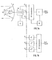
- the three receive outputs E 1 , E 2 , E 3 can - as shown in Fig. 1 a - feed an RF combiner, which is controlled by the receiver E via a control unit St, so that a high-frequency best signal is provided at its output, which is offered to the recipient E.
- the RF combiner can in a known manner, such as. B. in the journal NTG-Fachbericht, Vol. 70, p. 199, in the article "Electronic Space Diversity System for Directional Radio Systems” by Ulrich H. Sysel.
- an IF or a so-called baseband combiner can also be used, which is operated by three separate receivers E ', E ", E"'.
- Such an arrangement is described in a company brochure from Motorola "MVEC-70 Predetection Combiner".
- the H io shaft is suitable as the main lobe and the H 20 shaft as the angle diversity lobe (see German Patent 2626925).
- the H 10 wave can simultaneously serve as a carrier of the transmission signal.
- a field configuration results in the excitation aperture according to FIG. 2a and the shape of the antenna lobes according to FIG. 2b is derived therefrom.
- 3b schematically shows the associated lobe configuration as a level range. This lobe configuration is spread both in the azimuth and in the elevation plane and has four equal field strength maxima. All four individual clubs have the same maximum profit. 21 -wave and E HE 21 -Welle - in the case of a groove pathogen takes the place of the H 21st
- Fig. 4 shows in perspective the structure of a feed system for multi-mode diversity combination reception, consisting of exciter, subreflector and mode coupler.
- the mode coupler M has a total of four waveguide gates, three of which can be used for mode diversity combination reception (E i , E2, E3).
- the fourth gate (S) can be used as a transmission input.
- the output E 1 is coupled to the H 10 wave, E 2 to the H 11 + E 11 wave and E 3 to the H 20 wave.
- the input S transmits the orthogonal polarization (H 01 wave).
- the use of Gate S as a transmission input is an elegant way of separating transmission and reception. By decoupling the shaft types from one another, all reception gates are decoupled from the transmission gate.
- the vertical expansion lobe would look into the ground with its lower half of the lobe and lose a large part of its reception gain if the installation position was not rotated.
- the spreading angle is reduced by a factor in relation to the vertical plane so that with the same angle of attack of the antenna, a higher reception gain in the previously vertically spread diversity lobe can be expected.
- this measure also rotates the previously horizontally oriented spreading lobe by 45 °, so that the same conditions (due to the antenna orientation) can now be expected in both spreading lobes.
- the exciter horn is followed by a rectangular waveguide H, in which all the wave types to be evaluated must be viable.
- the energy components of the H 01 shaft and the H 20 shaft are coupled through a pair of axially oriented and pairwise opposite waveguide windows F and separated in a double-T junction T via symmetrical waveguides L 1 , L 2 .
- the separating plate B arranged symmetrically in the waveguide sections H i , H 2 prevents the H 01 wave from spreading into the rear section of the mode coupler H 2 .
- the position of the sheet B along the axis of the mode coupler is of decisive importance for the adaptation that can be achieved when coupling the H 01 shaft.
- the partition B has another task; it converts the H 11 + E 11 wave arriving from the exciter into two antiphase waveguide waves, the energy of which is then selectively coupled into the laterally attached waveguide E2 using a coupling bracket K.
- the H 10 shaft runs relatively undisturbed along the axis into the rear exit E i .
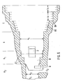
- a section (FIG. 5) in the H plane through the waveguide sections H, H 1 , H 2 and through the exciter horn E illustrates the internal structure of the feed system.
- the front waveguide H has the width a 1 and the height b i .
- This width enables the existence of the H 20 wave in the waveguide H, the height b, but not the existence of the H o2 wave, but the existence of the H 01 wave.
- the width is either reduced gradually (ST) or steadily to the dimension a 2 , which, together with an additional reduction in the waveguide height from b 1 to b 2, only permits the H 10 wave. If all of the shaft types described are used, care must be taken that the waveguide height b i is chosen so large that, in addition to the H 01 shaft to be transmitted, the H 11 + E 11 shaft remains viable up to the separating plate B.
- the diaphragm B can be pulled into the front waveguide H.
- a transmission signal to be transmitted must be transmitted in addition to the reception signal via gate 1 (H 01 wave), which is possible in a known manner by means of a circulator connection.
- the design of the pathogen is of particular importance in the case of a multi-mode diversity antenna. This is largely responsible for achieving high antenna gains.
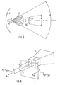
- the following illumination conditions result for a main wave type H lo and a higher wave type H 20 in the antenna according to FIG. 6. While a large part of the primary lobe HK of the main wave type H lo formed by the exciter falls on the subreflector SR in the illumination angle range a, that remains hatched area of the spreading lobe SK (H 20 shaft) outside the footprint and is therefore lost for the antenna gain. In this case, the normal expected antenna gain for the main lobe occurs, for the spreading lobe a significant decrease in profit has to be observed. In the classic case, a compromise between the two antenna lobes is possible, in which the beam angle is increased by changing the antenna geometry and more energy is used by the spreading lobe.
- additional measures according to the invention are intended to enable a further increase in antenna gain without having to compromise. This is achieved according to the invention in such a way that the primary lobes H 10 , H 01 belonging to the main shaft types are widened (see dashed line) without significantly narrowing the expansion lobe. After the widening has been carried out, the antenna geometry must be readjusted, ie the horn aperture or the subreflector is adapted to the new conditions.
- the introduction of a grooved exciter is very advantageous (symmetrical radiation, lobe shape in the H and E planes). Furthermore, by introducing step-shaped cross-sectional expansions or kinks as shown in FIG. 5, excitation of further hybrid wave types is achieved which achieve the desired beam-lobe broadening in both polarizations of the exciter (here HE 11 waves).
- the excited wave would be here in particular re to name the H 13 wave for the H plane or the HE 31 wave for the E plane, which, when superimposed with the HE 11 wave and with a suitable phase position, causes a field concentration in the center of the aperture of the exciter and thus the desired lobe broadening Consequence.
- the lengths 1 s of the steps or buckling sections and their distance 1 a to the excitation aperture are chosen such that the phase position shown in FIG. 7 is created.
- the cross-sectional structure of the horn is chosen to be square in all horn sections using both polarizations of the main shaft type (HE 11 ).
- the arrangement of several stages SH (Fig. 5) makes the effect described broadband.
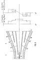
- FIG. 8 Let us first consider the level of the electric fields (FIG. 8). Basically, kinks, jumps, etc. are also possible here in order to obtain a broadening of the main shaft-type lobe, but the introduction of the apertures B 1 , B 2 , B 3 , B 4 results in a very simple possibility in the opposite way of the radiation lobes of the to align the higher wave type with its beam angle to the lobe of the main wave type. Rotational symmetry is achieved by choosing the aspect ratio of the rectangular aperture of the exciter horn.
- Fig. 8 the end of the separating plate B (mode coupler) together with the inner structure of the rectangular or square exciter horn E is drawn in section.
- the exciter horn is symmetrically divided into chambers by the diaphragms B 1 , B 2 , B 3 , B 4 .
- This chamber horn is known per se, but it is modified for use with several wave types in such a way that a widening of the radiation lobe of the main wave type H lo and a narrowing of the radiation lobe of the higher wave type H 11 + E 11 results in the E plane.
- the inclination of the diaphragms to the horn walls W results in a changed field distribution in the aperture plane A compared to the undisturbed (no diaphragms in the horn) conditions, which is schematically plotted along the straight line A.
- the originally expected, undisturbed distribution is shown in dashed lines.
- there is now a stronger field concentration in the middle of the exciter horn which leads to a broadening of the radiation lobe of the exciter horn. This measure only makes sense if at the same time the width of the radiation lobe assigned to (or derived from) the higher wave type remains the same or can possibly be made even narrower.
- Fig. 9 shows this arrangement, which consists of four partial waveguides opening into the exciter, all of which are connected together with magic T's (T 1 , T 2 , T 3 , T 4 ), so that the energies of the different wave types are available at their outputs .
Landscapes
- Engineering & Computer Science (AREA)
- Computer Networks & Wireless Communication (AREA)
- Signal Processing (AREA)
- Waveguide Aerials (AREA)
- Variable-Direction Aerials And Aerial Arrays (AREA)
- Aerials With Secondary Devices (AREA)
Description
In der Deutschen Patentschrift 2626925 ist ein Verfahren beschrieben, das die Auswirkungen der in Mikrowellenübertragungsstrecken vorkommenden statistischen Ausbreitungsschwankungen dadurch mildert, dass zur Gewinnung von Winkeldiversitysignalen mehr als ein Wellentyp in der hohlleitergespeisten Empfangsantenne angekoppelt wird. Dieses Verfahren geht von der Tatsache aus, dass in einem sehr grossen Prozentsatz der Übertragungsdauer mindestens ein Wellentyp ein auswertbares Empfangssignal liefert. Mit diesem bekannten Verfahren gelingt es, beispielsweise mit einer einzigen Empfangsantenne, ein Zweifach-Winkeldiversitysystem aufzubauen, das die beiden aus den unterschiedlichen Wellentypen gewonnenen Empfangssignale getrennten Empfängern zuführt und daraus ein Bestsignal ableitet.German patent 2626925 describes a method which mitigates the effects of the statistical fluctuations in the microwave transmission links by coupling more than one wave type in the waveguide-fed receiving antenna to obtain angle diversity signals. This method is based on the fact that, in a very large percentage of the transmission duration, at least one wave type delivers an evaluable reception signal. With this known method it is possible, for example with a single receiving antenna, to set up a dual-angle diversity system which feeds the two received signals obtained from the different wave types to separate receivers and derives a best signal therefrom.
Es ist auch möglich, für Mehrwegeübertragungsverfahren mehrere Antennen oder mehrere Erreger in einer Antenne zu verwenden. Das erfordert aber einen grossen Aufwand und führt bei mehreren Erregern in der Antenne zu Schwierigkeiten bei der Übertragung des Sendesignals, da der Spreizwinkel zwischen den einzelnen Strahlungskeulen, z. B. für die Troposcatterübertragung, viel zu gross ist.It is also possible to use multiple antennas or multiple exciters in one antenna for multipath transmission methods. However, this requires a lot of effort and leads to difficulties in the transmission of the transmission signal in the case of several exciters in the antenna, since the spread angle between the individual radiation lobes, e.g. B. for troposcatter transmission, is much too large.
Aus der US-PS 3274604 ist ein Richtungsfindungssystem (z. B. Monopuls-Radar) zur Ortung von bewegten reflektierenden Objekten bekannt, bei dem im Antennen-Speisesystem mehrere Hohlleiterwellentypen ausgenutzt werden. Hierbei liefert der auszuwertende Hauptwellentyp und die höheren Wellentypen eine Richtungsinformation des reflektierenden bewegten Objektes, so dass die Antenne entsprechend nachgeführt werden kann und eine Kanonensteuerung oder ein Raketenleitsystem entsprechend gesteuert werden kann. Mit der hier offenbarten Anordnung wird eine völlig andere Aufgabe gelöst, nämlich die Ortung eines bewegten Objektes.From US-PS 3274604 a direction finding system (z. B. monopulse radar) for locating moving reflecting objects is known, in which several types of waveguide waves are used in the antenna feed system. The main wave type to be evaluated and the higher wave types provide direction information of the reflecting moving object, so that the antenna can be tracked accordingly and a cannon control or a missile guidance system can be controlled accordingly. The arrangement disclosed here achieves a completely different task, namely the location of a moving object.
Der Erfindung liegt die Aufgabe zugrunde, eine Nachrichtenübertragungseinrichtung für Mikrowellen mit Mehrwegeausbreitung anzugeben, das nach dem Winkeldiversity-Prinzip arbeitet, mit nur einer Antenne und einem Erreger pro Endstelle auskommt und mit dem eine Vermehrung der voneinander unabhängigen Übertragungswege erreicht wird, dabei soll der Antennengewinn aller beteiligten Strahlungskeulen vergrössert werden, um eine wirkungsvollere Kombination der Empfangssignale zu einem Bestsignal zu erreichen, als es bisher möglich war, dabei soll der Sende- und Empfangsbetrieb auf einfache Weise, d. h. ohne zusätzlichen Zirkulator, gleichzeitig über diese eine Antenne möglich sein.The invention has for its object to provide a message transmission device for microwaves with multi-path propagation, which works on the angle diversity principle, works with only one antenna and one exciter per terminal and with which an increase in the independent transmission paths is achieved, the antenna gain of all Radiation lobes involved are increased in order to achieve a more effective combination of the received signals into a best signal than was previously possible. The transmit and receive operations should be simple, i. H. without an additional circulator, this antenna can be used simultaneously.
Die Aufgabe wird gelöst wie im Anspruch 1 beschrieben, die Unteransprüche geben vorteilhafte Weiterbildungen an.The object is achieved as described in claim 1, the subclaims indicate advantageous developments.
Im folgenden wird die Erfindung an Ausführungsbeispielen anhand von Figuren näher erläutert.
- Fig. 1a zeigt das Blockschaltbild einer Endstelle einer Funkübertragungsanlage mit Modendiversity, unter Verwendung eines HF-Kombinators;
- Fig. 1b zeigt in Ergänzung zu Fig. 1a eine Möglichkeit zur Verwendung eines ZF- bzw. Basisband-Kombinators;
- Fig. 2a zeigt das Feldbild der Hio- bzw. H2o-Welle in einem Rechteckhohlleiter.
- Fig. 2b zeigt die zu den H10- bzw. H20-Wellen gehörenden Strahlungskeulen in der Azimutebene;
- Fig. 2c zeigt das Feldbild der H11- bzw. E11-Welle und das dazu gehörende Summenfeld (H11 + E11) in einem Rechteckhohlleiter;
- Fig. 2d zeigt die zu den H10- bzw. (H11 + E11)-Wellen gehörenden Strahlungskeulen in der Elevationsebene;
- Fig. 3a zeigt das Feldbild der H21- bzw. E21-Welle und das dazu gehörende Summenfeld (H21 + E21) in einem Rechteckhohlleiter;
- Fig. 3b zeigt schematisch die Strahlungskeulen-Konfiguration des Summenfeldes H21 + E21 als Pegelgebirge;
- Fig. 4 zeigt den Modenkoppler M mit Erregerhorn E und Subreflektor SR;
- Fig. 5 zeigt einen Schnitt in der H-Ebene durch die Hohlleiterabschnitte H, H1, H2 und durch das Erregerhorn E;
- Fig. 6 zeigt die Ausleuchtverhältnisse der Hio-und H20-Welle bzw. H11 + E11)-Welle in der Antenne;
- Fig. 7 zeigt das Feldbild der HE11- bzw. HE13 und deren Summenfeld (HE11 + HE13) in einem Rechteckhohlleiter;
- Fig. 8 zeigt einen Schnitt in der E-Ebene durch die Hohlleiterabschnitte E und H und die Feldverteilung in der Aperturebene der H10- und der (H11 + E11)-Welle;
- Fig. 9 zeigt eine schematische Anordnung, die neben den Wellentypen H10, H11 + E11, H20 auch noch die Nutzung der (H21 + E21)-Wellen ermöglicht.
- 1a shows the block diagram of a terminal of a radio transmission system with mode diversity, using an RF combiner;
- 1b shows, in addition to FIG. 1a, one possibility of using an IF or baseband combiner;
- 2a shows the field image of the H io or H2o wave in a rectangular waveguide.
- 2b shows the radiation lobes belonging to the H 10 and H 20 waves in the azimuth plane;
- 2c shows the field image of the H 11 or E 11 wave and the associated sum field (H 11 + E 11 ) in a rectangular waveguide;
- 2d shows the radiation lobes belonging to the H 10 or (H 11 + E 11 ) waves in the elevation plane;
- 3a shows the field image of the H 21 or E 21 wave and the associated sum field (H 21 + E 21 ) in a rectangular waveguide;
- 3b schematically shows the radiation lobe configuration of the sum field H 21 + E 21 as level mountains;
- Fig. 4 shows the mode coupler M with exciter horn E and subreflector SR;
- Fig. 5 shows a section in the H plane through the waveguide sections H, H 1 , H 2 and through the excitation horn E;
- FIG. 6 shows the illumination conditions of the Hi and H 20 waves or H 11 + E 11 ) waves in the antenna;
- FIG. 7 shows the field image of the HE 11 or HE 13 and its sum field (HE 11 + HE 13 ) in a rectangular waveguide;
- 8 shows a section in the E plane through the waveguide sections E and H and the field distribution in the aperture plane of the H 10 and (H 11 + E 11 ) waves;
- FIG. 9 shows a schematic arrangement which, in addition to the wave types H 10 , H 11 + E 11 , H 20, also enables the use of the (H 21 + E 21 ) waves.
Die vorliegende Erfindung betrifft die Weiterentwicklung, d. h, Verbesserung des in der Deutschen Patentschrift 2626925 beschriebenen Verfahrens zur Sicherstellung eines unterbrechungsfreien Nachrichtenverkehrs mit einem Mikrowellenübertragungssystem mit Mehrwegeausbreitung. Üblicherweise besteht ein Mikrowellenübertragungssystem aus einem Funkfeld (ca. 40...150 km lang) und an den Enden aus jeweils mindestens einer Antenne mit Sende- und Empfangseinrichtungen. Bei Vorliegen einer Mehrwegeausbreitung in Funkfeldern, die beispielsweise keine optische Sicht aufweisen (z. B. Mikrowellenübertragung mit Hilfe der troposphärischen Streustrahlung), kommt es sehr häufig zu Schwundeinbrüchen des Empfangssignales durch Interferenz der Teilwellen. Diese Problematik wurde bisher durch das sogenannte Raumdiversityverfahren (mehrere Empfangsantennen) oder das Winkeidiversityverfahren (mehrere Erreger in einer Antenne) oder das Modendiversityverfahren (zwei Moden in einem Erreger einer Antenne) gelöst. In dem vorliegenden Ausführungsbeispiel werden drei Moden in einem Erreger einer Antenne ausgenutzt.The present invention relates to further development, i. h, improvement of the method described in German Patent 2626925 to ensure uninterrupted message traffic with a microwave transmission system with multipath propagation. A microwave transmission system usually consists of a radio field (approx. 40 ... 150 km long) and at the ends of at least one antenna with transmitting and receiving devices. If there is a multipath propagation in radio fields that, for example, do not have an optical view (e.g. microwave transmission with the help of tropospheric scattered radiation), the reception signal very often dips in due to interference of the partial waves. So far, this problem has been solved by the so-called spatial diversity method (multiple receiving antennas) or the wink diversity method (multiple exciters in one antenna) or the mode diversity method (two modes in one exciter of an antenna). In the present In the exemplary embodiment, three modes are used in one exciter of an antenna.
Als Antennensystem wird ein Cassegrain-System bevorzugt. Es besteht aus einem Hauptreflektor R, Subreflektor SR und Erregerhorn E. Die effektive Brennweite dieses Reflektortyps ist im allgemeinen grösser als bei einem fokusgespeisten Antennentyp. Dies hat zur Folge, dass die Erregerapertur c vergleichsweise grösser gewählt werden muss, was die Existenzfähigkeit höherer Hohlleiterwellentypen begünstigt. Die nachgeschaltete Modenweiche M trennt die Energieanteile verschiedener Wellentypen des Erregerhorns und liefert beispielsweise drei Empfangsausgänge Ei, E2, E3 und einen Sendeeingang S. Der Sendeeingang kann dem Wellentyp eines Empfangsausgangs zugeordnet sein.A Cassegrain system is preferred as the antenna system. It consists of a main reflector R, subreflector SR and exciter horn E. The effective focal length of this type of reflector is generally larger than that of a focus-fed antenna type. The consequence of this is that the excitation aperture c must be chosen to be comparatively larger, which favors the existence of higher waveguide types. The downstream mode switch M separates the energy components of different wave types of the excitation horn and provides, for example, three receive outputs E i , E2, E3 and one transmit input S. The transmit input can be assigned to the wave type of a receive output.
Die drei Empfangsausgänge E1, E2, E3 können - wie in Fig. 1 a gezeigt-einen HF-Kombinator speisen, der vom Empfänger E über eine Steuereinheit St gesteuert wird, so dass an seinem Ausgang ein hochfrequentes Bestsignal bereitgestellt wird, das dem Empfänger E angeboten wird.The three receive outputs E 1 , E 2 , E 3 can - as shown in Fig. 1 a - feed an RF combiner, which is controlled by the receiver E via a control unit St, so that a high-frequency best signal is provided at its output, which is offered to the recipient E.
Der HF-Kombinator kann in bekannter Weise, wie z. B. in der Zeitschrift NTG-Fachbericht, Bd. 70, S. 199, im Aufsatz «Elektronisches Raumdiversity-System für Richtfunkanlagen» von Ulrich H. Sysel beschrieben, aufgebaut sein.The RF combiner can in a known manner, such as. B. in the journal NTG-Fachbericht, Vol. 70, p. 199, in the article "Electronic Space Diversity System for Directional Radio Systems" by Ulrich H. Sysel.
Alternativ kann - wie in Fig. 1 b gezeigt - auch ein ZF- oder ein sogenannter Basisband-Kombinator eingesetzt werden, der von drei getrennten Empfängern E', E", E"' bedient wird. Eine solche Anordnung ist in einem Firmenprospekt der Firma Motorola «MVEC-70 Predetection Combiner» beschrieben.Alternatively, as shown in FIG. 1b, an IF or a so-called baseband combiner can also be used, which is operated by three separate receivers E ', E ", E"'. Such an arrangement is described in a company brochure from Motorola "MVEC-70 Predetection Combiner".
Zusätzlich zu diesen allgemeinen Merkmalen sollen nun einzelne Baugruppen des Modendiversityverfahrens beschrieben werden, die in ihrer erfindungsgemässen Gestaltung eine besonders hohe Übertragungsgüte ermöglichen.In addition to these general features, individual modules of the mode diversity method are now to be described which, in their design according to the invention, enable a particularly high transmission quality.
An erster Stelle steht hier das Antennensystem. Zunächst sollen Wellentypen genannt werden, die bei gegebener Erregerform unabhängige Winkeldiversitydiagramme erzeugen.In the first place is the antenna system. Initially, wave types are to be mentioned that generate independent angular diversity diagrams for a given excitation form.
Hier eignen sich die Hio-Welle als Hauptkeule und die H20-Welle als Winkeldiversitykeule (siehe Deutsche Patentschrift 2626925).The H io shaft is suitable as the main lobe and the H 20 shaft as the angle diversity lobe (see German Patent 2626925).
Die H10-Welle kann gleichzeitig als Träger des Sendesignals dienen. Bei vertikaler Polarisation des Gegensenders ergibt sich eine Feldkonfiguration in der Erregerapertur nach Fig. 2a und daraus abgeleitet die Form der Antennenkeulen nach Fig. 2b.The H 10 wave can simultaneously serve as a carrier of the transmission signal. In the case of vertical polarization of the opposing transmitter, a field configuration results in the excitation aperture according to FIG. 2a and the shape of the antenna lobes according to FIG. 2b is derived therefrom.
Zusätzlich zu diesem bekannten Zweifach-Modendiversityverfahren wird nun ein Dreifach-Diversitysystem dadurch erzeugt, dass zwei weitere Wellentypen (H11- und E11-Wellel verwendet werden, die so miteinander kombiniert werden, dass eine Spreizkeule in der Elevationsebene entsteht, die ebenfalls in einem breiten Frequenzbereich vertikal polarisiert ist. Die Feldkombination ist in Fig. 2c, die zugehörigen Strahlungskeulen sind in Fig. 2d gezeichnet.
- Im Falle eines rechteckigen Rillenerregers tritt
- anstelle der H10-Welle die HE11-Welle,
- anstelle der H20-Welle die HE21-Welle,
- anstelle der H11 + E11-Welle die HE12-Welle.
- In the case of a rectangular groove exciter
- instead of the H 10 shaft, the HE 11 shaft,
- instead of the H 20 shaft, the HE 21 shaft,
- instead of the H 11 + E 11 shaft, the HE 12 shaft.
Die Verwendung einer Kombination von zwei Wellentypen für die vertikale Spreizkeule (H11 + E11-Welle) ist in der Praxis kein Nachteil, da beide Wellentypen gleiche Ausbreitungskonstanten im Hohlleiter aufweisen und somit der Feldzustand der Apertur bei der Ausbreitung längs des Horns erhalten bleibt.In practice, the use of a combination of two wave types for the vertical expansion lobe (H 11 + E 11 wave) is not a disadvantage, since both wave types have the same propagation constants in the waveguide and the field state of the aperture is therefore preserved during the propagation along the horn.
Bei Rechteckerregern ist es möglich, auch noch eine vierte Diversitykeule zu erzeugen, die aus einer Kombination der H21- und E21-Welle hervorgeht. Diese Feldkonfiguration ist in Fig. 3a gezeichnet.In the case of rectangular exciters, it is also possible to generate a fourth diversity lobe, which results from a combination of the H 21 and E 21 waves. This field configuration is shown in Fig. 3a.
Fig. 3b zeigt schematisch die zugehörige Keulenkonfiguration als Pegelgebirge. Diese Keulenkonfiguration ist sowohl in der Azimut- als auch in der Elevations-Ebene gespreizt und hat vier gleich grosse Feldstärkemaxima. Alle vier Einzelkeulen haben gleichen Maximalgewinn. Im Falle eines Rillenerregers tritt an die Stelle der H21- und E21-Welle die HE21-Welle.3b schematically shows the associated lobe configuration as a level range. This lobe configuration is spread both in the azimuth and in the elevation plane and has four equal field strength maxima. All four individual clubs have the same maximum profit. 21 -wave and E HE 21 -Welle - in the case of a groove pathogen takes the place of the H 21st
Hier ist es schwieriger, breitbandig zwei Diversitykeulen (Spreizkeulen) zu erzeugen, die gleiche Polarisation wie die Hauptkeule aufweisen, da hierfür jede Spreizkeule aus jeweils zwei Wellentypen mit unterschiedlicher Ausbreitungskonstante erzeugt werden müssten.Here it is more difficult to generate broadband two diversity lobes (spreading lobes) that have the same polarization as the main lobe, since each spreading lobe would have to be generated from two wave types with different propagation constants.
Die nachfolgenden Beschreibungen erfindungsgemässer Speisesysteme gehen daher von rechteckigen Erregerquerschnitten aus.The following descriptions of the feed systems according to the invention are therefore based on rectangular exciter cross sections.
Fig. 4 zeigt perspektivisch den Aufbau eines Speisesystems für Mehrmodendiversity-Kombinationsempfang, bestehend aus Erreger, Subreflektor und Modenkoppler. Der Modenkoppler M hat insgesamt vier Hohlleitertore, von denen drei für Modendiversity-Kombinationsempfang ausgenutzt werden können (Ei, E2, E3). Das vierte Tor (S) kann als Sendeeingang genutzt werden. Der Ausgang E1 ist an die H10-Welle, E2 an die H11 + E11-Welle und E3 an die H20-Welle angekoppelt. Der Eingang S überträgt die orthogonale Polarisation (H01-Welle). Die Nutzung von Tor S als Sendeeingang stellt eine elegante Möglichkeit einer Sende-Empfangstrennung dar. Durch die Entkopplung der Wellentypen untereinander sind alle Empfangstore vom Sendetor entkoppelt. Diese Massnahme erfordert aber zwingend, dass auf der Gegenantenne das Speisesystem axial um 90° verdreht in den Reflektor eingebaut werden muss. Besonders günstige Verhältnisse ergeben sich dann, wenn beide Speisesysteme unter 45° zu der Horizontal- bzw. Vertikalebene (untereinander aber um 90° verdreht) angeordnet werden. Bei der Montage der Speisesysteme in die Antenne braucht dann auf die Einbaulage gegenüberstehender Antennen nicht mehr geachtet zu werden. Bei gleicher Montage der Erregersysteme ergibt sich die 90°-Verdrehung der Vektoren automatisch, da die Antennen im Betrieb gegeneinander ausgerichtet sind. Die axiale Verdrehung der Vektorebenen bringt noch einen weiteren Vorteil hinsichtlich der Spreizkeulen. Wenn die Antenne - was häufig der Fall ist-so ausgerichtet wird, dass die Hauptkeule nur wenig über den Horizont angehoben wird, so würden bei der nichtgedrehten Einbaulage die vertikale Spreizkeule mit ihrer unteren Keulenhälfte in die Erde blicken und einen Grossteil ihres Empfangsgewinns verlieren.Fig. 4 shows in perspective the structure of a feed system for multi-mode diversity combination reception, consisting of exciter, subreflector and mode coupler. The mode coupler M has a total of four waveguide gates, three of which can be used for mode diversity combination reception (E i , E2, E3). The fourth gate (S) can be used as a transmission input. The output E 1 is coupled to the H 10 wave, E 2 to the H 11 + E 11 wave and E 3 to the H 20 wave. The input S transmits the orthogonal polarization (H 01 wave). The use of Gate S as a transmission input is an elegant way of separating transmission and reception. By decoupling the shaft types from one another, all reception gates are decoupled from the transmission gate. However, this measure requires that the feed system on the counter antenna must be installed in the reflector, rotated by 90 °. Particularly favorable conditions result when the two supply systems are arranged at 45 ° to the horizontal or vertical plane (but rotated with one another by 90 °). When installing the feed systems in the antenna, it is then no longer necessary to pay attention to the installation position of opposing antennas. If the excitation systems are installed in the same way, the vectors are rotated 90 ° automatically, since the antennas are aligned with one another during operation. The axial rotation of the vector planes brings yet another advantage with regard to the expansion lobes. If the antenna - which is often the case - is aligned so that the main lobe is only slightly raised above the horizon, the vertical expansion lobe would look into the ground with its lower half of the lobe and lose a large part of its reception gain if the installation position was not rotated.
Bei der um 45° gedrehten Einbaulage verringert sich bezogen auf die Vertikalebene der Spreizwinkel um den Faktor
Nach diesen grundsätzlichen Bemerkungen söll nun näher auf die Ausgestaltung des Modenkopplers M (Fig. 4) eingegangen werden.After these basic remarks, the configuration of the mode coupler M (FIG. 4) should now be discussed in more detail.
Dem Erregerhorn folgt ein rechteckiger Hohlleiter H, in dem alle auszuwertenden Wellentypen existenzfähig sein müssen. Durch ein Paar von axial orientierten und paarweise gegenüberliegenden Hohlleiterfenstern F werden die Energieanteile der H01-Welle, sowie der H20-Welle angekoppelt und über symmetrische Hohlleiter L1, L2 in einer Doppel-T-Verzweigung T getrennt. Das symmetrisch in den Hohlleiterabschnitten Hi, H2 angeordnete Trennblech B verhindert eine Ausbreitung der H01-Welle in den hinteren Abschnitt des Modenkopplers H2. Gleichzeitig ist die Lage des Blechs B längs der Achse des Modenkopplers von entscheidender Bedeutung für die erreichbare Anpassung bei der Ankopplung der H01-Welle. Das Trennblech B hat noch eine weitere Aufgabe; es führt die vom Erreger ankommende H11 + E11-Welle in zwei gegenphasige Hohlleiterwellen über, deren Energie dann selektiv mit einem Koppelbügel K in den seitlich aufgesetzten Hohlleiter E2 eingekoppelt wird. Die H10-Welle läuft längs der Achse relativ ungestört in den hinteren Ausgang Ei. Ein Schnitt (Fig. 5) in der H-Ebene durch die Hohlleiterabschnitte H, H1, H2 und durch das Erregerhorn E verdeutlicht den inneren Aufbau des Speisesystems.The exciter horn is followed by a rectangular waveguide H, in which all the wave types to be evaluated must be viable. The energy components of the H 01 shaft and the H 20 shaft are coupled through a pair of axially oriented and pairwise opposite waveguide windows F and separated in a double-T junction T via symmetrical waveguides L 1 , L 2 . The separating plate B arranged symmetrically in the waveguide sections H i , H 2 prevents the H 01 wave from spreading into the rear section of the mode coupler H 2 . At the same time, the position of the sheet B along the axis of the mode coupler is of decisive importance for the adaptation that can be achieved when coupling the H 01 shaft. The partition B has another task; it converts the H 11 + E 11 wave arriving from the exciter into two antiphase waveguide waves, the energy of which is then selectively coupled into the laterally attached waveguide E2 using a coupling bracket K. The H 10 shaft runs relatively undisturbed along the axis into the rear exit E i . A section (FIG. 5) in the H plane through the waveguide sections H, H 1 , H 2 and through the exciter horn E illustrates the internal structure of the feed system.
Der vordere Hohlleiter H habe die Breite a1 und die Höhe bi. Diese Breite ermöglicht die Existenz der H20-Welle im Hohlleiter H, die Höhe b, jedoch nicht die Existenz der Ho2-Welle, aber die Existenz der H01-Welle. Etwa in Höhe der Einkoppelfenster F wird die Breite entweder stufenweise (ST) oder stetig auf das Mass a2 reduziert, das zusammen mit einer zusätzlichen Reduzierung der Hohlleiterhöhe von b1 auf b2 nur noch die H10-Welle zulässt. Im Falle der Verwendung aller beschriebener Wellentypen muss darauf geachtet werden, dass die Hohlleiterhöhe bi so gross gewählt wird, dass neben der zu übertragenden H01-Welle auch die H11 + E11-Welle bis zum Trennblech B existenzfähig bleibt. Bei einer möglichen vereinfachten Ausführung des Kopplers, die keine Verwendung der H01-Welle erfordert, kann die Blende B bis in den vorderen Hohlleiter H vorgezogen werden. In diesem Falle muss aber ein zu übertragendes Sendesignal zusätzlich zum Empfangssignal über das Tor 1 (H01-Welle) übertragen werden, was in bekannter Weise mittels Zirkulatoraufschaltung möglich ist.The front waveguide H has the width a 1 and the height b i . This width enables the existence of the H 20 wave in the waveguide H, the height b, but not the existence of the H o2 wave, but the existence of the H 01 wave. Approximately at the level of the coupling-in window F, the width is either reduced gradually (ST) or steadily to the dimension a 2 , which, together with an additional reduction in the waveguide height from b 1 to b 2, only permits the H 10 wave. If all of the shaft types described are used, care must be taken that the waveguide height b i is chosen so large that, in addition to the H 01 shaft to be transmitted, the H 11 + E 11 shaft remains viable up to the separating plate B. In the case of a possible simplified version of the coupler, which does not require the use of the H 01 shaft, the diaphragm B can be pulled into the front waveguide H. In this case, however, a transmission signal to be transmitted must be transmitted in addition to the reception signal via gate 1 (H 01 wave), which is possible in a known manner by means of a circulator connection.
Besondere Bedeutung kommt bei einer Mehrmodendiversityantenne der Ausgestaltung des Erregers zu. Dieser ist massgeblich für die Erreichung hoher Antennengewinne verantwortlich.The design of the pathogen is of particular importance in the case of a multi-mode diversity antenna. This is largely responsible for achieving high antenna gains.
Es werden nun Massnahmen beschrieben, die eine Gewinnoptimierung für alle beteiligten Wellentypen ermöglichen. Mit klassischen Massnahmen (z. B. Einführung eines Rillenerregers) ist nur eine Gewinnoptimierung für die orthogonal polarisierten Hauptwellentypen H10, H01 möglich.Measures are now described which enable profit optimization for all wave types involved. With classic measures (e.g. introduction of a groove exciter) only a profit optimization for the orthogonally polarized main shaft types H 10 , H 01 is possible.
In der Praxis ergeben sich für einen Hauptwellentyp Hlo und einen höheren Wellentyp H20 in der Antenne folgende Ausleuchtverhältnisse nach Fig. 6. Während ein Grossteil der vom Erreger gebildeten Primärkeule HK des Hauptwellentyps Hlo im Ausleuchtwinkelbereich a auf den Subreflektor SR fällt, bleibt der schraffierte Bereich der Spreizkeule SK (H20-Welle) ausserhalb der Ausleuchtzone und geht damit für den Antennengewinn verloren. Es stellt sich in diesem Falle der normal zu erwartende Antennengewinn für die Hauptkeule ein, für die Spreizkeule ist eine deutliche Gewinnabnahme zu beachten. Im klassischen Falle ist ein Kompromiss zwischen beiden Antennenkeulen möglich, in dem durch Ändern der Antennengeometrie der Ausleuchtwinkel vergrössert wird und dadurch mehr Energie der Spreizkeule genutzt wird. Hier soll jedoch durch zusätzliche erfindungsgemässe Massnahmen eine weitere Steigerung des Antennengewinns ermöglicht werden, ohne einen Kompromiss eingehen zu müssen. Erfindungsgemäss wird dies so erreicht, dass die zu den Hauptwellentypen gehörenden Primärkeulen H10, H01 verbreitert werden (siehe gestrichelte Linie), ohne die Spreizkeule wesentlich zu verschmälern. Nach Durchführung der Verbreiterung muss die Antennengeometrie neu angepasst werden, d. h. die Hornapertur oder der Subreflektor wird an die neuen Verhältnisse angepasst.In practice, the following illumination conditions result for a main wave type H lo and a higher wave type H 20 in the antenna according to FIG. 6. While a large part of the primary lobe HK of the main wave type H lo formed by the exciter falls on the subreflector SR in the illumination angle range a, that remains hatched area of the spreading lobe SK (H 20 shaft) outside the footprint and is therefore lost for the antenna gain. In this case, the normal expected antenna gain for the main lobe occurs, for the spreading lobe a significant decrease in profit has to be observed. In the classic case, a compromise between the two antenna lobes is possible, in which the beam angle is increased by changing the antenna geometry and more energy is used by the spreading lobe. However, additional measures according to the invention are intended to enable a further increase in antenna gain without having to compromise. This is achieved according to the invention in such a way that the primary lobes H 10 , H 01 belonging to the main shaft types are widened (see dashed line) without significantly narrowing the expansion lobe. After the widening has been carried out, the antenna geometry must be readjusted, ie the horn aperture or the subreflector is adapted to the new conditions.
Bei der Nutzung beider Hauptwellentypen Hio, H01 ist zunächst die Einführung eines Rillenerregers sehr vorteilhaft (symmetrische Strahlungs- .Keulenform in H- und E-Ebene). Weiterhin wird durch Einführung von stufenförmigen Querschnittserweiterungen bzw. von Knickstellen gemäss Fig. 5 eine Anregung weiterer Hybridwellentypen erreicht, die in beiden ausgenutzten Polarisationen des Erregers (hier HE11-Wellen) die gewünschte Strahlen-Keulenverbreiterung erreichen. Als angeregte Welle wären hier insbesondere die H13-Welle für H-Ebene bzw. die HE31-Welle für die E-Ebene zu nennen, die in Überlagerung mit der HE11-Welle bei geeigneter Phasenlage eine Feldkonzentration in Aperturmitte des Erregers bewirkt und somit die gewünschte Keulenverbreiterung zur Folge hat.When using both main shaft types H io , H 01 , the introduction of a grooved exciter is very advantageous (symmetrical radiation, lobe shape in the H and E planes). Furthermore, by introducing step-shaped cross-sectional expansions or kinks as shown in FIG. 5, excitation of further hybrid wave types is achieved which achieve the desired beam-lobe broadening in both polarizations of the exciter (here HE 11 waves). The excited wave would be here in particular re to name the H 13 wave for the H plane or the HE 31 wave for the E plane, which, when superimposed with the HE 11 wave and with a suitable phase position, causes a field concentration in the center of the aperture of the exciter and thus the desired lobe broadening Consequence.
Fig. 7 zeigt diese Verhältnisse für die Verbreiterung in der E-Ebene. Die Längen 1s der Stufen bzw. Knickabschnitte und ihr Abstand 1a zur Erregerapertur wird so gewählt, dass die in Fig. 7 gezeigte Phasenlage entsteht. Die Querschnitts-Struktur des Horns wird bei Ausnutzung beider Polarisationen des Hauptwellentyps (HE11) in allen Hornabschnitten quadratisch gewählt. Die Anordnung mehrerer Stufen SH (Fig. 5) macht den beschriebenen Effekt breitbandig.7 shows these relationships for the broadening in the E plane. The lengths 1 s of the steps or buckling sections and their distance 1 a to the excitation aperture are chosen such that the phase position shown in FIG. 7 is created. The cross-sectional structure of the horn is chosen to be square in all horn sections using both polarizations of the main shaft type (HE 11 ). The arrangement of several stages SH (Fig. 5) makes the effect described broadband.
Eine interessante Möglichkeit, die beschriebene Verbreiterung der Hauptkeule im Erregersystem mit sehr einfachen Mitteln durchzuführen, ergibt sich dann, wenn nur ein Hauptwellentyp Hlo im Antennensystem genutzt werden soll. Hier kann auf die Rillenstruktur im Erregerhorn verzichtet werden. Die Massnahmen zur Strahlungskeulenverbreiterung müssen aber dann in den beiden Hauptebenen des Erregers unterschiedlich ausgeführt werden.An interesting possibility to carry out the described broadening of the main lobe in the excitation system with very simple means arises when only one main wave type H lo is to be used in the antenna system. The groove structure in the exciter horn can be dispensed with here. The measures for widening the lobe must then be carried out differently in the two main levels of the pathogen.
Zunächst sei die Ebene der elektrischen Felder betrachtet (Fig. 8). Grundsätzlich sind auch hier Knickstellen, Sprünge usw. möglich, um eine Verbreiterung der Keule des Hauptwellentyps zu erhalten, jedoch ergibt sich hier durch Einführung der Blenden B1, B2, B3, B4 eine sehr einfache Möglichkeit im umgekehrten Wege die Strahlungskeulen des höheren Wellentyps in ihrem Ausleuchtwinkel an die Keule des Hauptwellentyps anzugleichen. Rotationssymmetrie erreicht man durch die Wahl des Seitenverhältnisses der Rechteckapertur des Erregerhorns.Let us first consider the level of the electric fields (FIG. 8). Basically, kinks, jumps, etc. are also possible here in order to obtain a broadening of the main shaft-type lobe, but the introduction of the apertures B 1 , B 2 , B 3 , B 4 results in a very simple possibility in the opposite way of the radiation lobes of the to align the higher wave type with its beam angle to the lobe of the main wave type. Rotational symmetry is achieved by choosing the aspect ratio of the rectangular aperture of the exciter horn.
In Fig. 8 ist das Ende des Trennblechs B (Modenkoppler) zusammen mit der Innenstruktur des rechteckigen bzw. quadratischen Erregerhorns E im Schnitt gezeichnet. Das Erregerhorn ist symmetrisch durch die Blenden B1, B2, B3, B4 in Kammern unterteilt. Dieses Kammerhorn ist an sich bekannt, es wird aber für die Anwendung mit mehreren Wellentypen so modifiziert, dass sich in der E-Ebene eine Verbreiterung der Strahlungskeule des Hauptwellentyps Hlo und eine Verschmälerung der Strahlenkeulen des höheren Wellentyps H11 + E11 ergibt. Dies wird so erreicht, dass die inneren Kammern (zwischen B1, B2) an ihrem Anfang (in der Nähe des Trennbleches B) so dimensioniert ist, dass in ihr die von B ausgehende H11 + E11-Welle nicht ausbreitungsfähig ist. Die von dem Hohlleiterabschnitt H ausgehenden Hio-Wellen werden durch die Blenden B1, B2, B3, B4 leistungsgemäss gemäss dem geometrischen Teilerverhältnis aufgeteilt und in den zwischen den Blenden gebildeten Hohlleitern weitergeleitet, zwischen B1 und B2 entsteht auch eine H10-Welle. Durch die Neigung der Blenden zu den Hornwänden W ergibt sich in der Aperturebene A eine gegenüber den ungestörten (keine Blenden im Horn) Verhältnissen geänderte Feldverteilung, die längs der Geraden A, schematisch aufgetragen ist. Die ursprünglich zu erwartende, ungestörte Verteilung ist gestrichelt gezeichnet. Gegenüber der ehemals konstanten Verteilung entsteht jetzt eine stärkere Feldkonzentration in der Mitte des Erregerhorns, was zu einer Verbreiterung der Strahlungskeule des Erregerhorns führt. Diese Massnahme hat nur dann einen Sinn, wenn gleichzeitig die dem höheren Wellentyp zugeordnete (oder davon abgeleitete) Strahlungskeule in ihrer Breite gleichbleibt oder eventuell noch schmäler gemacht werden kann. Dies wird durch die längs der Achse A2 aufgetragene Feldverteilung der aus der H11 + E11-Welle hervorgegangenen Teilwellen erreicht. Bei der gezeigten Blendenkonfiguration entsteht in der Mittenzone ein feldtoter Raum. Dadurch werden die beiden gegenphasigen Feldzentren Z1, Z2 weiter auseinandergerückt, wodurch die resultierenden Strahlungskeulen verschmälert werden. Ganz wesentlich ist an dieser Verschmälerung auch der Feldstärkeabfall zum Aperturrand des Erregers hin beteiligt. Im Erreger ohne Blenden treten am Rande Feldstärkenmaxima auf, die zu sehr kräftigen Streufeldern (Beugung, Mantelströme) am Erregerrand führen und daher die Strahlungskeulen verbreitern (Feldverteilung gestrichelt gezeichnet). Durch den Übergang der von B ausgehenden H11 + E11-Welle in den Hohlleiterabschnitt mit den Blenden B1, B2 entsteht eine elektrische Stossstelle (feldtoter Raum zwischen Bl, B2). Die dadurch bedingte Reflexion lässt sich jedoch durch eine Blindleitungsanordnung, z. B. in Form eines axial angeordneten leitenden Stiftes KS wiederum kompensieren. Dieser Stift KS hat, sofern er genügend dünn ist, keine schädliche Rückwirkung auf die ebenfalls zu übertragende H10-Welle.In Fig. 8 the end of the separating plate B (mode coupler) together with the inner structure of the rectangular or square exciter horn E is drawn in section. The exciter horn is symmetrically divided into chambers by the diaphragms B 1 , B 2 , B 3 , B 4 . This chamber horn is known per se, but it is modified for use with several wave types in such a way that a widening of the radiation lobe of the main wave type H lo and a narrowing of the radiation lobe of the higher wave type H 11 + E 11 results in the E plane. This is achieved in such a way that the inner chambers (between B 1 , B 2 ) are dimensioned at their beginning (in the vicinity of the separating plate B) in such a way that the H 11 + E 11 wave originating from B is not able to propagate in them. The H io waves emanating from the waveguide section H are divided by the apertures B 1 , B 2 , B 3 , B 4 in accordance with the geometric division ratio and passed on in the waveguides formed between the apertures, and there is also a between B 1 and B 2 H 10 shaft. The inclination of the diaphragms to the horn walls W results in a changed field distribution in the aperture plane A compared to the undisturbed (no diaphragms in the horn) conditions, which is schematically plotted along the straight line A. The originally expected, undisturbed distribution is shown in dashed lines. Compared to the previously constant distribution, there is now a stronger field concentration in the middle of the exciter horn, which leads to a broadening of the radiation lobe of the exciter horn. This measure only makes sense if at the same time the width of the radiation lobe assigned to (or derived from) the higher wave type remains the same or can possibly be made even narrower. This is achieved by the field distribution along the axis A 2 of the partial waves resulting from the H 11 + E 11 wave. In the diaphragm configuration shown, a field-dead space is created in the middle zone. As a result, the two opposite-phase field centers Z 1 , Z 2 are moved further apart, as a result of which the resulting radiation lobes are narrowed. The decrease in field strength to the aperture edge of the exciter is also very significantly involved in this narrowing. In the exciter without apertures, field strength maxima occur at the edge, which lead to very strong stray fields (diffraction, sheath currents) at the exciter edge and therefore widen the radiation lobes (field distribution shown in dashed lines). The transition of the H 11 + E 11 wave originating from B into the waveguide section with the apertures B 1 , B 2 creates an electrical impact point (dead space between B 1 , B 2 ). The reflection caused by this can, however, by a blind line arrangement, for. B. again in the form of an axially arranged conductive pin KS. Provided that it is sufficiently thin, this KS pin has no harmful effect on the H 10 shaft which is also to be transmitted.
In der H-Ebene des Erregers müssen ebenfalls Massnahmen zur Beeinflussung der Strahlungskeulenbreiten getroffen werden. Hier ist jedoch keine neue Abbildung erforderlich; es kann auf die Querschnittsstufen und Knickstellen der Fig. 5 verwiesen werden. Auf die Rillenstruktur im Inneren des Erregers kann aber verzichtet werden. Die Querschnittssprünge regen insbesondere die H30-Welle an, so dass bei geeigneter Phasenlage zum Feld der H10-Welle in der Apertur eine geänderte Feldverteilung entsteht, die eine Verbreiterung der abgestrahlten Keule des Hauptwellentyps erbringt.In the H-plane of the exciter, measures must also be taken to influence the beam lobe widths. However, no new mapping is required here; reference can be made to the cross-sectional steps and kinks in FIG. 5. The groove structure inside the pathogen can be dispensed with. The cross-sectional jumps particularly stimulate the H 30 wave, so that with a suitable phase relationship to the field of the H 10 wave, a changed field distribution is created in the aperture, which results in a broadening of the radiated lobe of the main wave type.
Zum Schluss sei noch ein völlig anders aufgebautes Speisesystem vorgestellt, das neben den Wellentypen H10, H11 + E11, H20 auch noch die Nutzung der H21 + E21-Welle ermöglicht.Finally, a completely different feed system is presented, which in addition to the shaft types H 10 , H 11 + E 11 , H 20 also enables the use of the H 21 + E 21 shaft.
Fig. 9 zeigt diese Anordnung, die aus vier in den Erreger mündenden Teilhohlleitern besteht, die alle mit magischen T's (T1, T2, T3, T4) zusammengeschaltet werden, so dass an deren Ausgängen die Energien der verschiedenen Wellentypen verfügbar sind.Fig. 9 shows this arrangement, which consists of four partial waveguides opening into the exciter, all of which are connected together with magic T's (T 1 , T 2 , T 3 , T 4 ), so that the energies of the different wave types are available at their outputs .
Claims (4)
Applications Claiming Priority (2)
| Application Number | Priority Date | Filing Date | Title |
|---|---|---|---|
| DE19813111731 DE3111731A1 (en) | 1981-03-25 | 1981-03-25 | MICROWAVE TRANSMISSION DEVICE WITH MULTI-MODE DIVERSITY COMBINATION RECEPTION |
| DE3111731 | 1981-03-25 |
Publications (2)
| Publication Number | Publication Date |
|---|---|
| EP0061576A1 EP0061576A1 (en) | 1982-10-06 |
| EP0061576B1 true EP0061576B1 (en) | 1985-05-02 |
Family
ID=6128248
Family Applications (1)
| Application Number | Title | Priority Date | Filing Date |
|---|---|---|---|
| EP82101197A Expired EP0061576B1 (en) | 1981-03-25 | 1982-02-18 | Microwave communication transmission apparatus with multimode diversity combining reception |
Country Status (4)
| Country | Link |
|---|---|
| US (1) | US4473828A (en) |
| EP (1) | EP0061576B1 (en) |
| CA (1) | CA1180801A (en) |
| DE (2) | DE3111731A1 (en) |
Cited By (2)
| Publication number | Priority date | Publication date | Assignee | Title |
|---|---|---|---|---|
| DE3604432A1 (en) * | 1986-02-13 | 1987-08-20 | Licentia Gmbh | Mode coupler for monopulse applications |
| DE3840450A1 (en) * | 1988-12-01 | 1990-06-07 | Telefunken Systemtechnik | MODEM COUPLER FOR MONOPULATION APPLICATIONS |
Families Citing this family (26)
| Publication number | Priority date | Publication date | Assignee | Title |
|---|---|---|---|---|
| FR2503938A1 (en) * | 1981-04-10 | 1982-10-15 | Thomson Csf | COMPACT DIFFERENTIAL COUPLER FOR RADAR MONOPULSE |
| DE3331023C2 (en) * | 1983-08-27 | 1985-09-05 | ANT Nachrichtentechnik GmbH, 7150 Backnang | Antenna excitation system with several horn antennas |
| US4764775A (en) * | 1985-04-01 | 1988-08-16 | Hercules Defense Electronics Systems, Inc. | Multi-mode feed horn |
| US4914443A (en) * | 1988-07-26 | 1990-04-03 | At&T Bell Laboratories | Angle diversity signal separator using mode conversion |
| US5095535A (en) * | 1988-07-28 | 1992-03-10 | Motorola, Inc. | High bit rate communication system for overcoming multipath |
| US5182569A (en) * | 1988-09-23 | 1993-01-26 | Alcatel N.V. | Antenna having a circularly symmetrical reflector |
| ATE146907T1 (en) * | 1989-10-09 | 1997-01-15 | Bosch Gmbh Robert | ANGLE DIVERSITY ARRANGEMENT |
| US4994819A (en) * | 1989-11-24 | 1991-02-19 | Bell Communications Research, Inc. | Pattern diversity in a microwave digital radio system utilizing a single horn reflector antenna |
| DE4013562C2 (en) * | 1990-04-27 | 1994-11-24 | Ant Nachrichtentech | Diversity reception arrangement |
| DE9017701U1 (en) * | 1990-09-18 | 1992-01-23 | Richard Hirschmann GmbH & Co, 7300 Esslingen | Radio link antenna arrangement |
| US5760749A (en) * | 1994-03-17 | 1998-06-02 | Fujitsu Limited | Antenna integral-type transmitter/receiver system |
| EP0674355B1 (en) * | 1994-03-21 | 2003-05-21 | Hughes Electronics Corporation | Simplified tracking antenna |
| US5515009A (en) * | 1994-09-13 | 1996-05-07 | Rockwell International Corporation | Space-fed horn for quasi-optical spatial power combiners |
| US5663693A (en) * | 1995-08-31 | 1997-09-02 | Rockwell International | Dielectric waveguide power combiner |
| US6041219A (en) * | 1998-10-01 | 2000-03-21 | Wytec, Incorporated | Integrated orthogonal mode transducer/filter design for microwave frequency-domain |
| US6163304A (en) * | 1999-03-16 | 2000-12-19 | Trw Inc. | Multimode, multi-step antenna feed horn |
| US7130590B2 (en) * | 2001-09-07 | 2006-10-31 | Remec Broadband Wireless Holdings, Inc. | Transceiver assembly |
| GB0306642D0 (en) * | 2003-03-22 | 2003-04-30 | Dca Design Int Ltd | Improvements in and relating to an injector for a medical product |
| GB0405112D0 (en) * | 2004-03-06 | 2004-04-07 | Univ Belfast | Single aperature monopulse antenna |
| DE102010063800A1 (en) * | 2010-12-21 | 2012-06-21 | Endress + Hauser Gmbh + Co. Kg | Diplexer for homodyne FMCW radar |
| CN103138036B (en) * | 2013-02-05 | 2015-10-07 | 广东通宇通讯股份有限公司 | Microwave communication system and compact four-way transducer thereof |
| DE102013011651A1 (en) * | 2013-07-11 | 2015-01-15 | ESA-microwave service GmbH | Antenna feed system in the microwave range for reflector antennas |
| DE102016014385A1 (en) * | 2016-12-02 | 2018-06-07 | Kathrein-Werke Kg | Dual polarized horn |
| US11784384B2 (en) | 2017-12-20 | 2023-10-10 | Optisys, LLC | Integrated tracking antenna array combiner network |
| WO2019191917A1 (en) * | 2018-04-04 | 2019-10-10 | 华为技术有限公司 | Omt component and omt apparatus |
| US20220368000A1 (en) | 2021-05-14 | 2022-11-17 | Optisys, Inc. | Planar monolithic combiner and multiplexer for antenna arrays |
Family Cites Families (7)
| Publication number | Priority date | Publication date | Assignee | Title |
|---|---|---|---|---|
| US3274604A (en) * | 1958-12-12 | 1966-09-20 | Bernard L Lewis | Multi-mode simultaneous lobing antenna |
| FR1571407A (en) * | 1968-04-10 | 1969-06-20 | ||
| CA890032A (en) * | 1970-08-10 | 1972-01-04 | Wu Chuang-Jy | Microwave horn-paraboloidal antenna |
| US3877031A (en) * | 1973-06-29 | 1975-04-08 | Unied States Of America As Rep | Method and apparatus for suppressing grating lobes in an electronically scanned antenna array |
| DE2626925C3 (en) * | 1976-06-16 | 1981-01-08 | Licentia Patent-Verwaltungs-Gmbh, 6000 Frankfurt | Method for compensating for propagation fluctuations in communication systems |
| DE2626926C2 (en) * | 1976-06-16 | 1983-08-25 | AEG-Telefunken Nachrichtentechnik GmbH, 7150 Backnang | Waveguide primary radiator with rectangular cross-section for a reflector antenna with beam swivel |
| US4420756A (en) * | 1981-01-19 | 1983-12-13 | Trw Inc. | Multi-mode tracking antenna feed system |
-
1981
- 1981-03-25 DE DE19813111731 patent/DE3111731A1/en not_active Withdrawn
-
1982
- 1982-02-18 EP EP82101197A patent/EP0061576B1/en not_active Expired
- 1982-02-18 DE DE8282101197T patent/DE3263344D1/en not_active Expired
- 1982-03-24 US US06/361,451 patent/US4473828A/en not_active Expired - Fee Related
- 1982-03-24 CA CA000399297A patent/CA1180801A/en not_active Expired
Cited By (2)
| Publication number | Priority date | Publication date | Assignee | Title |
|---|---|---|---|---|
| DE3604432A1 (en) * | 1986-02-13 | 1987-08-20 | Licentia Gmbh | Mode coupler for monopulse applications |
| DE3840450A1 (en) * | 1988-12-01 | 1990-06-07 | Telefunken Systemtechnik | MODEM COUPLER FOR MONOPULATION APPLICATIONS |
Also Published As
| Publication number | Publication date |
|---|---|
| US4473828A (en) | 1984-09-25 |
| DE3111731A1 (en) | 1982-10-14 |
| CA1180801A (en) | 1985-01-08 |
| DE3263344D1 (en) | 1985-06-05 |
| EP0061576A1 (en) | 1982-10-06 |
Similar Documents
| Publication | Publication Date | Title |
|---|---|---|
| EP0061576B1 (en) | Microwave communication transmission apparatus with multimode diversity combining reception | |
| DE60009874T2 (en) | V-slot antenna for circular polarization | |
| DE69111298T2 (en) | Antenna for dual linear and dual circular polarization. | |
| DE69715518T2 (en) | Antenna feeder for multiple frequencies | |
| DE69524296T2 (en) | Printed antenna with two beam directions | |
| DE3931752A1 (en) | COAXIAL SLOT ANTENNA | |
| DE69016479T2 (en) | Spotlight for circularly polarized weles with low cross polarization. | |
| EP0041077B1 (en) | Antenna-feeding system for a tracking antenna | |
| EP1341260A1 (en) | Antenna for receiving satellite and/or terrestrial radio signals in cars | |
| DE1942678C3 (en) | Feed arrangement for an antenna working with several wave types | |
| DE2140082A1 (en) | Autonomous collision warning system for aircraft | |
| DE3786664T2 (en) | MICROWAVE EXCITER FOR ORTHOGONAL POLARIZED WAVES. | |
| DE10195823B3 (en) | Antenna element, transceiver and method of operating a transceiver | |
| DE2855280A1 (en) | ANTENNA LINE, IN PARTICULAR SLOT ANTENNA LINE | |
| DE3840450A1 (en) | MODEM COUPLER FOR MONOPULATION APPLICATIONS | |
| DE2810483C2 (en) | Antenna with a feed waveguide having slots and a radiator line enclosing an angle with this | |
| DE112017000933T5 (en) | Radar with range-independent resolution | |
| DE10205379A1 (en) | Device for transmitting and receiving electromagnetic radiation | |
| DE2434924B2 (en) | ANTENNA SYSTEM FOR A PRIMARY AND SECONDARY RADAR WITH REFLECTOR, PRIMARY BEAM AND TWO AUXILIARY BEAMS | |
| DE19719953A1 (en) | Vehicle radar sensor e.g. for distance warning | |
| DE2719283C2 (en) | Antenna feed system for double polarization | |
| DE951732C (en) | Ultra-short wave transmission system with at least two transmission channels | |
| DE2626926C2 (en) | Waveguide primary radiator with rectangular cross-section for a reflector antenna with beam swivel | |
| DE2104467C3 (en) | Electrical communication system for the transmission of high-frequency signals | |
| EP0422431B1 (en) | Angular-diversity device |
Legal Events
| Date | Code | Title | Description |
|---|---|---|---|
| PUAI | Public reference made under article 153(3) epc to a published international application that has entered the european phase |
Free format text: ORIGINAL CODE: 0009012 |
|
| AK | Designated contracting states |
Designated state(s): CH DE FR GB IT LI NL |
|
| RAP1 | Party data changed (applicant data changed or rights of an application transferred) |
Owner name: AEG - TELEFUNKEN NACHRICHTENTECHNIK GMBH |
|
| 17P | Request for examination filed |
Effective date: 19830317 |
|
| RAP1 | Party data changed (applicant data changed or rights of an application transferred) |
Owner name: ANT NACHRICHTENTECHNIK GMBH |
|
| ITF | It: translation for a ep patent filed | ||
| GRAA | (expected) grant |
Free format text: ORIGINAL CODE: 0009210 |
|
| AK | Designated contracting states |
Designated state(s): CH DE FR GB IT LI NL |
|
| REF | Corresponds to: |
Ref document number: 3263344 Country of ref document: DE Date of ref document: 19850605 |
|
| ET | Fr: translation filed | ||
| PLBE | No opposition filed within time limit |
Free format text: ORIGINAL CODE: 0009261 |
|
| STAA | Information on the status of an ep patent application or granted ep patent |
Free format text: STATUS: NO OPPOSITION FILED WITHIN TIME LIMIT |
|
| 26N | No opposition filed | ||
| ITTA | It: last paid annual fee | ||
| REG | Reference to a national code |
Ref country code: GB Ref legal event code: 746 |
|
| REG | Reference to a national code |
Ref country code: FR Ref legal event code: DL |
|
| PGFP | Annual fee paid to national office [announced via postgrant information from national office to epo] |
Ref country code: GB Payment date: 19940207 Year of fee payment: 13 |
|
| PGFP | Annual fee paid to national office [announced via postgrant information from national office to epo] |
Ref country code: NL Payment date: 19940228 Year of fee payment: 13 |
|
| PGFP | Annual fee paid to national office [announced via postgrant information from national office to epo] |
Ref country code: CH Payment date: 19940316 Year of fee payment: 13 |
|
| PGFP | Annual fee paid to national office [announced via postgrant information from national office to epo] |
Ref country code: DE Payment date: 19941222 Year of fee payment: 14 |
|
| PGFP | Annual fee paid to national office [announced via postgrant information from national office to epo] |
Ref country code: FR Payment date: 19950214 Year of fee payment: 14 |
|
| PG25 | Lapsed in a contracting state [announced via postgrant information from national office to epo] |
Ref country code: GB Effective date: 19950218 |
|
| PG25 | Lapsed in a contracting state [announced via postgrant information from national office to epo] |
Ref country code: LI Effective date: 19950228 Ref country code: CH Effective date: 19950228 |
|
| PG25 | Lapsed in a contracting state [announced via postgrant information from national office to epo] |
Ref country code: NL Effective date: 19950901 |
|
| GBPC | Gb: european patent ceased through non-payment of renewal fee |
Effective date: 19950218 |
|
| NLV4 | Nl: lapsed or anulled due to non-payment of the annual fee |
Effective date: 19950901 |
|
| PG25 | Lapsed in a contracting state [announced via postgrant information from national office to epo] |
Ref country code: FR Effective date: 19961031 |
|
| PG25 | Lapsed in a contracting state [announced via postgrant information from national office to epo] |
Ref country code: DE Effective date: 19961101 |
|
| REG | Reference to a national code |
Ref country code: FR Ref legal event code: ST |