EP0061203A1 - Machine gun and ejection system therefor - Google Patents
Machine gun and ejection system therefor Download PDFInfo
- Publication number
- EP0061203A1 EP0061203A1 EP82103633A EP82103633A EP0061203A1 EP 0061203 A1 EP0061203 A1 EP 0061203A1 EP 82103633 A EP82103633 A EP 82103633A EP 82103633 A EP82103633 A EP 82103633A EP 0061203 A1 EP0061203 A1 EP 0061203A1
- Authority
- EP
- European Patent Office
- Prior art keywords
- belt
- ejection hole
- housing
- ammunition
- round
- Prior art date
- Legal status (The legal status is an assumption and is not a legal conclusion. Google has not performed a legal analysis and makes no representation as to the accuracy of the status listed.)
- Granted
Links
Images


Classifications
-
- F—MECHANICAL ENGINEERING; LIGHTING; HEATING; WEAPONS; BLASTING
- F41—WEAPONS
- F41A—FUNCTIONAL FEATURES OR DETAILS COMMON TO BOTH SMALLARMS AND ORDNANCE, e.g. CANNONS; MOUNTINGS FOR SMALLARMS OR ORDNANCE
- F41A9/00—Feeding or loading of ammunition; Magazines; Guiding means for the extracting of cartridges
- F41A9/38—Loading arrangements, i.e. for bringing the ammunition into the firing position
- F41A9/45—Loading arrangements, i.e. for bringing the ammunition into the firing position the cartridge chamber or the barrel as a whole being tiltable or transversely slidable between a loading and a firing position
-
- F—MECHANICAL ENGINEERING; LIGHTING; HEATING; WEAPONS; BLASTING
- F41—WEAPONS
- F41A—FUNCTIONAL FEATURES OR DETAILS COMMON TO BOTH SMALLARMS AND ORDNANCE, e.g. CANNONS; MOUNTINGS FOR SMALLARMS OR ORDNANCE
- F41A15/00—Cartridge extractors, i.e. devices for pulling cartridges or cartridge cases at least partially out of the cartridge chamber; Cartridge ejectors, i.e. devices for throwing the extracted cartridges or cartridge cases free of the gun
-
- F—MECHANICAL ENGINEERING; LIGHTING; HEATING; WEAPONS; BLASTING
- F41—WEAPONS
- F41A—FUNCTIONAL FEATURES OR DETAILS COMMON TO BOTH SMALLARMS AND ORDNANCE, e.g. CANNONS; MOUNTINGS FOR SMALLARMS OR ORDNANCE
- F41A9/00—Feeding or loading of ammunition; Magazines; Guiding means for the extracting of cartridges
- F41A9/35—Feeding multibarrel guns
-
- F—MECHANICAL ENGINEERING; LIGHTING; HEATING; WEAPONS; BLASTING
- F41—WEAPONS
- F41A—FUNCTIONAL FEATURES OR DETAILS COMMON TO BOTH SMALLARMS AND ORDNANCE, e.g. CANNONS; MOUNTINGS FOR SMALLARMS OR ORDNANCE
- F41A9/00—Feeding or loading of ammunition; Magazines; Guiding means for the extracting of cartridges
- F41A9/38—Loading arrangements, i.e. for bringing the ammunition into the firing position
- F41A9/39—Ramming arrangements
- F41A9/42—Rammers separate from breech-block
Definitions
- This invention relates to an externally powered machine gun having multiple fixed barrels, and to an ejection system therefor; more particularly the invention relates to such a gun having a housing, a motor means mounted on the housing for powering the gun, a gearing means mounted onto the housing and operably connected to the motor means for driving various operations of the gun in predetermined phased relationships, feed means operably connected to the gearing means for supplying ammunition to the gun, two parallel barrels fixedly mounted to the housing, a firing chamber alignable with each barrel, and an ejection hole in the housing for ejecting spent cartridges from the feed means.
- U.K. Patent Specification 577,338 discloses a gun of this type in which ammunition is fed from a magazine to a linearly-reciprocating breech block arranged to move within a bolt race aligned with each barrel, spent ammunition being ejected laterally therefrom. The speed of operation of this arrangement is limited by virtue of the ammunition feed and ejection systems employed.
- the present invention provides a machine gun of the above-defined type, having an improved ejection system, characterised in that the ejection hole ejects spent cartridges from the feed means in a forward direction, and a belt is mounted on the housing and operably connected to the motor means for movement in a forward axial direction away from the ejection hole such that the belt frictionally grasps any cartridges ejecting from the ejection hole and axially accelerates them to ensure the cartridge is completely withdrawn from the ejection hole before the feed means moves to another position.
- U.S. Patent No. 2,725,791 discloses an ejection mechanism for a gun mounted in a turret which mechanism uses a pair of endless belts to receive cartridges which are laterally ejected from the side of the gun (in similar manner to the gun disclosed in the aforementioned U.K. Patent Specification Nc. 577,338).
- the mechanism does not grip the cartridges until after full ejection from the slot in the side of the gun, in contrast to the present invention wherein ejecting cartridges are grasped and accelerated to ensure complete withdrawal from the ejection hole; thus the cartridges are grasped whilst still within the ejection hole (and in the preferred embodiment still partially in the bore of a movable shuttle) and the ejection system then accelerates the cartridges fully out of the ejection hole in the forward axial direction.
- the prior arrangement merely acts to dispose of fully-ejected cartridges and thus is not applicable to increasing the possible speed of operation of the gun.
- the belt is an endless looped belt pivotably mounted on the housing, the motor means being operably connected to pulleys for driving the belt such that the belt surface facing the edge of the ejection hole moves away therefrom in the forward axial direction.
- the ejection hole and belt are preferably disposed between the barrels of the gun; this allows a movable shuttle to be positioned firstly so as to allow an incoming round of ammunition to eject a spent cartridge through the ejection hole for acceleration by the belt, and secondly so that the round of ammunition is aligned with one of the barrels.
- roller bearings are provided spaced apart from the belt surface so that ejecting cartridges are gripped between the belt and bearings and accelerated by movement of the belt.
- a machine gun 10 has two vertically spaced barrels 12 and 14 mounted to a housing 16. A gap 18 is formed between the two barrels 12 and 14.
- the housing 16 houses a gearing system generally indicated at 20 which is operably driven by motor 22.
- the gearing system 20, as more clearly shown in Figure 2, is operably connected to a feed system generally indicated as 21.
- the feed system 21 includes a pair of augers 23 and 24 which are rotatably mounted about parallel axes which are transverse to the longitudinal axes of the barrels 12 and 14.
- Auger 23 has toothed gear 27 mounted thereon and auger 24 has toothed gear 29 coaxially mounted thereon.
- a pinion gear 31 is mounted between gears 27 and 29 and meshes therewith to cause both to rotate in the same direction.
- Gear 33 of gearing system 20 meshes with gear 27 to drive the augers 23 and 24.
- Each auger 23 and 24 has a helical groove 26 wrapped about its surface and axially ends with a zero pitch portion of the groove which forms a grooved ring 28 thereabout.
- Each auger 23 and 24 is positioned such that the upper portions of each helical groove 26 are longitudinally aligned to receive a round of ammunition thereon which enters from slot 30 in housing 16. Ammunition is delivered through slot 30 by conveyor belt (not shown) in a known manner.
- the housing 16 has a vertical wall 32 which slideably mounts an upper firing pin 34 and a lower firing pin 36 therein.
- the wall 32 has an aperture 38 therethrough which is aligned in front of the upper portions of aligned grooved rings 28.
- the wall 32 forms the rear portion of a vertically disposed compartment 40 which slideably houses a shuttle 42.
- the shuttle 42 is snugly received in compartment 40 such that the rear wall 32 abuts the rear end 44 of the shuttle and a front wall 46 of compartment 40 abuts the front end 48 of the shuttle 42.
- Side walls 50 and 52 of the compartment 40 have vertically extending grooves 54 therein which receive integral guide projections 56 extending from shuttle 42.
- Wall 50 also has a vertical extending slot 58 situated between the two grooves 54.
- Front wall 46 has an aperture 60 therethrough leading to lower barrel 14 and as shown in Figure 4, an aperture 61 leads to upper barrel 12. Between apertures 60 and 61, wall 46 has a central aperture 62 therethrough in communication with central gap 18. Aperture 62 is coaxially aligned with aperture 38.
- the shuttle 42 has an upper bore 64 and a lower bore 66, which are parallel and vertically spaced apart extending from the rear end 44 to front end 48 of shuttle 42.
- the barrels 12 and 14, apertures 38 and 62, and bores 64 and 66 are spaced such that when the shuttle is in its lower position, as shown in Figures 2 and 4, the lower bore 66 is in communication with barrel 14 through aperture 60 and in communication with firing pin 36, and the upper bore 64 is aligned with apertures 38 and 62.
- the bore 66 is in alignment with apertures 38 and 62, and the bore 64 is aligned with barrel 12 through aperture tg, and in communication with firing pin 34.
- the shuttle has an integral lug 63 passing through slot 58 for driving the shuttle up and down between its two positions.
- the integral lug 63 is driven by a drive system which includes a circumferential groove 65 on drum 67 which is rotatably mounted about a vertical axis. Coaxially mounted to the drum 67 is a toothed gear 72 mounted onto pin 74.
- the toothed gear 72 meshes with a toothed gear 70 which is attached to a shaft 68 which is driven by the gearing system 20.
- An endless conveyor belt 76 is mounted to housing 16 in front of aperture 62.
- the belt 76 is mounted about drive pulleys 78 which are operably linked in conventional fashion (not shown) to gearing system 20.
- the belt 76 is made from a suitable plastic material having a curved outer surface 80 with notches 82 spaced thereabout to aid in achieving the proper flexibility of the belt.
- the belt 76 is driven in a clockwise direction as shown in Figure 2 such that its side 84 is driven forwardly away from aperture 62.
- a series of roller bearings 86 is spaced apart from surface 84 such that a round of ammunition may extend between roller bearings 86 and belt surface 80 of side 84.
- a cam deflector 88 extends forwardly from belt 76 and bends to a side direction.
- Each firing pin 34 and 36 is driven by a cam which is coaxially mounted onto drum 67.
- cam 90 has an outer surface 92 which spirals outwardly with shoulder section 94 radially connecting the inner spiral end with the outer spiral end.
- the cam 90 as shown rotates in a counter clockwise direction and abuts a tappet 96 which is resiliently biased by spring 98 compressed between a collar 100 rigidly secured on tappet 96 and a flange 102 of housing 16.
- the tappet 96 has a knuckle end 104 pivotably mounted to firing pin lever 106 which is pivotably connected to housing 16 at one end 107 and to firing pin 34 at its other end 109. Firing pin 34 slideably extends through aperture 108 in wall 32. As the cam 90 rotates, the tappet 96 is biased to abut the surface 92 which, when rotated will withdraw the firing pin from compartment 40 and when shoulder 94 passes, tappet 96 will spring bias the firing pin 34 into the compartment 40 to abut a round of ammunition placed therein.
- the ramming system 91 is driven by a toothed crank 112 which has a connecting rod 114.pivotably mounted about pivot pin 116 radially displaced from the center of rotation 118 of the crank 112.
- a toothed rack 120 is mounted on the side of housing 16.
- the connecting rod 114 has a pinion gear 124 at end 122.
- the gear 124 engages the teeth 126 on rack 120.
- Slidably mounted within slot 128 is a ram shaft 130 which also engages pinion gear 124 by means of its teeth 132.
- Ram shaft 130 has ram lug 134 which engages the rear end of round 136 of ammunition.
- a claw 138 is pivotably mounted about pin 140 and engages a groove 142 within the cartridge portion of round 136.
- a camming edge 129 engages the claw to disengage it from groove 142 when the shaft 130 completely pushes round 136 into one of the bores 64 or 66.
- gear 33 of the gearing system 20 drives the toothed gears 27, 29, and 31 to rotate the augers 23 and 24 as shown in Figure 2 in a clockwise direction.
- a conveyor system (not shown) delivers ammunition to slot 30 which the augers 23 and 24 can receive in their aligned grooves 26 one at a time.
- the augers 23 and 24, rotate and move the engaged ammunition round transversely across until the round is resting in the grooved rings 28.
- the augers 23 and 24 continuously move but the round of ammunition as shown in Figure 4 obtains a dwell position due to the zero pitch of the rings 28.
- a round of ammunition 136 is in its dwell position in rings 28, the continuously rotating crank wheel 112, as shown in Figure 3, starts to drive the ram shaft 130 forward which accelerates the round through aperture 38 and into bore 64 as shown in Figure 4.
- the shuttle is driven by continuously rotating drum 67 from its first dwell position upwardly in a linear fashion until bore 64 . 61 is then aligned with aperture -98. At this point the drum 67 creates a second dwell position at which the bore 64 is aligned with the barrel 12 and with its back end 44 flush against the wall 32 and the firing pin 34 directly behind the round 136.
- the bore 64 and rear wall 32 form a firing chamber for the round 136.
- the cam 90 has shoulder 94 pass by tappet 96 so that the firing pin is spring biased against the round 136 through aperture 108 to set off the round 136.
- the cam 90 Upon firing of round 136, the cam 90 immediately starts to withdraw the firing pin 34 from the chamber 64.
- a second round is delivered onto the grooved ring position 28 to be rammed by the ram shaft 130 into bore 66 which is now aligned with aperture 38. Any spent cartridge within bore 66 is then ejected, in the same fashion as a spent cartridge in bore 64, out through aperture 62 and accelerated by acceleration belt 76.
- the shuttle As the second round is positioned within bore 66 and the projectile .is fired from bore 64, the shuttle then is driven by drum cam 67 back to its first dwell position wherein bore 66 is aligned with barrel 14 and firing pin 36 directly behind the new incoming round in bore 66. Bore 66 and wall 32 form a firing chamber for the second round. Bore 64 is realigned with aperture 38 and 62. At this point the firing pin 36 is operated to set off the new incoming round in bore 66 and the spent cartridge in 64 is then ejected in the same fashion by a third round being driven by ram shaft 130.
- the shuttle is linearly driven between two positions and forms firing chambers for two fixed barrels.
- the feed system feeds both bores in the shuttle.
- Two continuously moving augers and a continuously moving drum allows for a simpler and lighter design due to the elimination of stop-go motion which creates higher stress loads.
- the needed dwell positions are accommodated by the sinusoidal motion of the crank 112 and the zero pitch of the ring grooves in the augers and the shape of the groove in the drum.
- the acceleration belt insures that during start-up any spent cartridge is quickly and fully withdrawn from the bores in the shuttle so that any risk of jamming is kept to a minimum.
- a lightweight compact externally powered machine gun is designed with a minimum amount of motion and with capabilities of shooting over three thousand rounds per minute.
Abstract
Description
- This invention relates to an externally powered machine gun having multiple fixed barrels, and to an ejection system therefor; more particularly the invention relates to such a gun having a housing, a motor means mounted on the housing for powering the gun, a gearing means mounted onto the housing and operably connected to the motor means for driving various operations of the gun in predetermined phased relationships, feed means operably connected to the gearing means for supplying ammunition to the gun, two parallel barrels fixedly mounted to the housing, a firing chamber alignable with each barrel, and an ejection hole in the housing for ejecting spent cartridges from the feed means.
- U.K. Patent Specification 577,338 discloses a gun of this type in which ammunition is fed from a magazine to a linearly-reciprocating breech block arranged to move within a bolt race aligned with each barrel, spent ammunition being ejected laterally therefrom. The speed of operation of this arrangement is limited by virtue of the ammunition feed and ejection systems employed.
- More recently, advances in rapid fire guns have produced guns capable of firing over three thousand rounds per minute. With such capabilities, it is extremely important to have feed and ejection systems which move the rounds of ammunition to the firing chamber in line with the barrel with the minimum amount of movement and eject spent cartridges from the firing chamber as quickly as possible. Some examples of such guns are disclosed in U.S. Patents 3,667,147, 2,977,854 and 2,973,692.
- In our co-pending European Patent Application No. 80301956.1 (Publication No. 0,021,717) from which the present application is divided, there is claimed a machine gun having an improved feed system in the form of a linearly reciprocally moving shuttle having parallel and spaced bores forming the firing chambers of the gun.
- The present invention provides a machine gun of the above-defined type, having an improved ejection system, characterised in that the ejection hole ejects spent cartridges from the feed means in a forward direction, and a belt is mounted on the housing and operably connected to the motor means for movement in a forward axial direction away from the ejection hole such that the belt frictionally grasps any cartridges ejecting from the ejection hole and axially accelerates them to ensure the cartridge is completely withdrawn from the ejection hole before the feed means moves to another position.
- U.S. Patent No. 2,725,791 discloses an ejection mechanism for a gun mounted in a turret which mechanism uses a pair of endless belts to receive cartridges which are laterally ejected from the side of the gun (in similar manner to the gun disclosed in the aforementioned U.K. Patent Specification Nc. 577,338). As described, the mechanism does not grip the cartridges until after full ejection from the slot in the side of the gun, in contrast to the present invention wherein ejecting cartridges are grasped and accelerated to ensure complete withdrawal from the ejection hole; thus the cartridges are grasped whilst still within the ejection hole (and in the preferred embodiment still partially in the bore of a movable shuttle) and the ejection system then accelerates the cartridges fully out of the ejection hole in the forward axial direction. The prior arrangement merely acts to dispose of fully-ejected cartridges and thus is not applicable to increasing the possible speed of operation of the gun.
- In the preferred embodiment of the invention, the belt is an endless looped belt pivotably mounted on the housing, the motor means being operably connected to pulleys for driving the belt such that the belt surface facing the edge of the ejection hole moves away therefrom in the forward axial direction. The ejection hole and belt are preferably disposed between the barrels of the gun; this allows a movable shuttle to be positioned firstly so as to allow an incoming round of ammunition to eject a spent cartridge through the ejection hole for acceleration by the belt, and secondly so that the round of ammunition is aligned with one of the barrels. Preferably, roller bearings are provided spaced apart from the belt surface so that ejecting cartridges are gripped between the belt and bearings and accelerated by movement of the belt.
- In order that the present invention may be more readily understood, an embodiment thereof will now be described by way of example, with reference to the accompanying drawings, in which:-
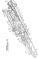
- Figure 1 is a front perspective view of one embodiment of the invention;
- Figure 2 is a partially broken and fragmentary view of the embodiment of Figure 1;
- Figure 3 is another partially broken and fragmentary view of the embodiment shown in Figure 1; and
- Figure 4 is a side elevational partially sectional and fragmentary view of the embodiment shown in Figure 1.
- Referring now to the Figures, particularly Figure 1, a machine gun 10 has two vertically spaced
barrels 12 and 14 mounted to ahousing 16. Agap 18 is formed between the twobarrels 12 and 14. Thehousing 16 houses a gearing system generally indicated at 20 which is operably driven by motor 22. - The
gearing system 20, as more clearly shown in Figure 2, is operably connected to a feed system generally indicated as 21. Thefeed system 21 includes a pair ofaugers 23 and 24 which are rotatably mounted about parallel axes which are transverse to the longitudinal axes of thebarrels 12 and 14. Auger 23 has toothed gear 27 mounted thereon and auger 24 has toothed gear 29 coaxially mounted thereon. A pinion gear 31 is mounted between gears 27 and 29 and meshes therewith to cause both to rotate in the same direction.Gear 33 ofgearing system 20 meshes with gear 27 to drive theaugers 23 and 24. Eachauger 23 and 24 has a helical groove 26 wrapped about its surface and axially ends with a zero pitch portion of the groove which forms a grooved ring 28 thereabout. Eachauger 23 and 24 is positioned such that the upper portions of each helical groove 26 are longitudinally aligned to receive a round of ammunition thereon which enters from slot 30 inhousing 16. Ammunition is delivered through slot 30 by conveyor belt (not shown) in a known manner. - The
housing 16 has avertical wall 32 which slideably mounts anupper firing pin 34 and alower firing pin 36 therein. Thewall 32 has anaperture 38 therethrough which is aligned in front of the upper portions of aligned grooved rings 28. - The
wall 32 forms the rear portion of a vertically disposedcompartment 40 which slideably houses a shuttle 42. The shuttle 42 is snugly received incompartment 40 such that therear wall 32 abuts the rear end 44 of the shuttle and afront wall 46 ofcompartment 40 abuts thefront end 48 of the shuttle 42.Side walls 50 and 52 of thecompartment 40 have vertically extendinggrooves 54 therein which receive integral guide projections 56 extending from shuttle 42.Wall 50 also has a vertical extending slot 58 situated between the twogrooves 54. -
Front wall 46 has an aperture 60 therethrough leading tolower barrel 14 and as shown in Figure 4, an aperture 61 leads to upper barrel 12. Between apertures 60 and 61,wall 46 has acentral aperture 62 therethrough in communication withcentral gap 18. Aperture 62 is coaxially aligned withaperture 38. - The shuttle 42 has an
upper bore 64 and alower bore 66, which are parallel and vertically spaced apart extending from the rear end 44 tofront end 48 of shuttle 42. Thebarrels 12 and 14,apertures bores lower bore 66 is in communication withbarrel 14 through aperture 60 and in communication withfiring pin 36, and theupper bore 64 is aligned withapertures bore 66 is in alignment withapertures bore 64 is aligned with barrel 12 through aperture tg, and in communication withfiring pin 34. - Referring back to Figure 2, the shuttle has an integral lug 63 passing through slot 58 for driving the shuttle up and down between its two positions. The integral lug 63 is driven by a drive system which includes a
circumferential groove 65 ondrum 67 which is rotatably mounted about a vertical axis. Coaxially mounted to thedrum 67 is atoothed gear 72 mounted ontopin 74. Thetoothed gear 72 meshes with atoothed gear 70 which is attached to ashaft 68 which is driven by thegearing system 20. - An
endless conveyor belt 76 is mounted tohousing 16 in front ofaperture 62. Thebelt 76 is mounted aboutdrive pulleys 78 which are operably linked in conventional fashion (not shown) to gearingsystem 20. Thebelt 76 is made from a suitable plastic material having a curved outer surface 80 with notches 82 spaced thereabout to aid in achieving the proper flexibility of the belt. Thebelt 76 is driven in a clockwise direction as shown in Figure 2 such that itsside 84 is driven forwardly away fromaperture 62. - A series of
roller bearings 86, as clearly shown in Figure 1, is spaced apart fromsurface 84 such that a round of ammunition may extend betweenroller bearings 86 and belt surface 80 ofside 84. Acam deflector 88 extends forwardly frombelt 76 and bends to a side direction. - Referring to Figure 3, the
firing pin system 89 and ramming mechanism portion 91 offeed system 21 will now be described. Eachfiring pin drum 67. For simplicity only theupper cam 90 is shown with only theupper firing pin 34 since the upper and lower firing pin systems are identical.Cam 90 has an outer surface 92 which spirals outwardly withshoulder section 94 radially connecting the inner spiral end with the outer spiral end. Thecam 90 as shown rotates in a counter clockwise direction and abuts atappet 96 which is resiliently biased byspring 98 compressed between acollar 100 rigidly secured ontappet 96 and a flange 102 ofhousing 16. Thetappet 96 has a knuckle end 104 pivotably mounted to firingpin lever 106 which is pivotably connected tohousing 16 at oneend 107 and to firingpin 34 at itsother end 109. Firingpin 34 slideably extends throughaperture 108 inwall 32. As thecam 90 rotates, thetappet 96 is biased to abut the surface 92 which, when rotated will withdraw the firing pin fromcompartment 40 and whenshoulder 94 passes,tappet 96 will spring bias thefiring pin 34 into thecompartment 40 to abut a round of ammunition placed therein. - The ramming system 91 is driven by a toothed crank 112 which has a connecting rod 114.pivotably mounted about pivot pin 116 radially displaced from the center of
rotation 118 of the crank 112. A toothed rack 120 is mounted on the side ofhousing 16. The connecting rod 114 has apinion gear 124 at end 122. Thegear 124 engages theteeth 126 on rack 120. Slidably mounted withinslot 128 is aram shaft 130 which also engagespinion gear 124 by means of itsteeth 132.Ram shaft 130 hasram lug 134 which engages the rear end ofround 136 of ammunition. A claw 138 is pivotably mounted about pin 140 and engages a groove 142 within the cartridge portion ofround 136. A camming edge 129 engages the claw to disengage it from groove 142 when theshaft 130 completely pushes round 136 into one of thebores - When the motor 22 is actuated,
gear 33 of thegearing system 20 drives the toothed gears 27, 29, and 31 to rotate theaugers 23 and 24 as shown in Figure 2 in a clockwise direction. A conveyor system (not shown) delivers ammunition to slot 30 which theaugers 23 and 24 can receive in their aligned grooves 26 one at a time. Theaugers 23 and 24, rotate and move the engaged ammunition round transversely across until the round is resting in the grooved rings 28. Theaugers 23 and 24 continuously move but the round of ammunition as shown in Figure 4 obtains a dwell position due to the zero pitch of the rings 28. When a round ofammunition 136 is in its dwell position in rings 28, the continuously rotating crank wheel 112, as shown in Figure 3, starts to drive theram shaft 130 forward which accelerates the round throughaperture 38 and intobore 64 as shown in Figure 4. - Any spent cartridge within
bore 64 is simultaneously pushed out throughaperture 62 by the intrusion ofround 136 until belt 80 which is rapidly driven in a forward axial direction frictionally grasps the spent cartridge and whips it out todeflection cam 88 which deflects any spent cartridge sideways away from the line of fire. - As the
round 136 begins to be fully inserted inbore 64, theram shaft 130 decelerates due to the sinusoidal motion rendered by crank 112. Claw 138 retains theround 136 so it does not accelerate ahead ofpush lug 134 so thatround 136 is gently placed withinbore 64. At this point, camming edge 129 releases the claw 138 fromgroove 132 and the crank 112 withdraws theshaft 130 passing thelug 134 over the now empty ring grooves 28. - Once
round 136 is withinbore 64, the shuttle is driven by continuously rotatingdrum 67 from its first dwell position upwardly in a linear fashion untilbore 64 . 61 is then aligned with aperture -98. At this point thedrum 67 creates a second dwell position at which thebore 64 is aligned with the barrel 12 and with its back end 44 flush against thewall 32 and thefiring pin 34 directly behind theround 136. Thebore 64 andrear wall 32 form a firing chamber for theround 136. At this point thecam 90 hasshoulder 94 pass bytappet 96 so that the firing pin is spring biased against theround 136 throughaperture 108 to set off theround 136. Upon firing ofround 136, thecam 90 immediately starts to withdraw thefiring pin 34 from thechamber 64. - Simultaneously, a second round is delivered onto the grooved ring position 28 to be rammed by the
ram shaft 130 intobore 66 which is now aligned withaperture 38. Any spent cartridge withinbore 66 is then ejected, in the same fashion as a spent cartridge inbore 64, out throughaperture 62 and accelerated byacceleration belt 76. As the second round is positioned withinbore 66 and the projectile .is fired frombore 64, the shuttle then is driven bydrum cam 67 back to its first dwell position wherein bore 66 is aligned withbarrel 14 andfiring pin 36 directly behind the new incoming round inbore 66.Bore 66 andwall 32 form a firing chamber for the second round.Bore 64 is realigned withaperture firing pin 36 is operated to set off the new incoming round inbore 66 and the spent cartridge in 64 is then ejected in the same fashion by a third round being driven byram shaft 130. - In this fashion, the shuttle is linearly driven between two positions and forms firing chambers for two fixed barrels. The feed system feeds both bores in the shuttle. Two continuously moving augers and a continuously moving drum allows for a simpler and lighter design due to the elimination of stop-go motion which creates higher stress loads. The needed dwell positions are accommodated by the sinusoidal motion of the crank 112 and the zero pitch of the ring grooves in the augers and the shape of the groove in the drum.
- The acceleration belt insures that during start-up any spent cartridge is quickly and fully withdrawn from the bores in the shuttle so that any risk of jamming is kept to a minimum.
- In this fashion, a lightweight compact externally powered machine gun is designed with a minimum amount of motion and with capabilities of shooting over three thousand rounds per minute.
Claims (5)
characterised in that:
Applications Claiming Priority (2)
| Application Number | Priority Date | Filing Date | Title |
|---|---|---|---|
| US47402 | 1979-06-11 | ||
| US06/047,402 US4309933A (en) | 1979-06-11 | 1979-06-11 | Externally powered gun loading and ejection system |
Related Parent Applications (1)
| Application Number | Title | Priority Date | Filing Date |
|---|---|---|---|
| EP80301956.1 Division | 1980-06-10 |
Publications (2)
| Publication Number | Publication Date |
|---|---|
| EP0061203A1 true EP0061203A1 (en) | 1982-09-29 |
| EP0061203B1 EP0061203B1 (en) | 1984-04-25 |
Family
ID=21948760
Family Applications (3)
| Application Number | Title | Priority Date | Filing Date |
|---|---|---|---|
| EP82103634A Expired EP0061204B1 (en) | 1979-06-11 | 1980-06-10 | Machine gun and feed system therefor |
| EP80301956A Expired EP0021717B1 (en) | 1979-06-11 | 1980-06-10 | Machine gun and feed system therefor |
| EP82103633A Expired EP0061203B1 (en) | 1979-06-11 | 1980-06-10 | Machine gun and ejection system therefor |
Family Applications Before (2)
| Application Number | Title | Priority Date | Filing Date |
|---|---|---|---|
| EP82103634A Expired EP0061204B1 (en) | 1979-06-11 | 1980-06-10 | Machine gun and feed system therefor |
| EP80301956A Expired EP0021717B1 (en) | 1979-06-11 | 1980-06-10 | Machine gun and feed system therefor |
Country Status (3)
| Country | Link |
|---|---|
| US (1) | US4309933A (en) |
| EP (3) | EP0061204B1 (en) |
| DE (1) | DE3067930D1 (en) |
Families Citing this family (7)
| Publication number | Priority date | Publication date | Assignee | Title |
|---|---|---|---|---|
| DE3069622D1 (en) * | 1980-04-11 | 1984-12-20 | Ford Aerospace & Communication | Reciprocating feed system and automatic machine gun incorporating same |
| DE3237728C2 (en) * | 1982-10-12 | 1985-02-07 | Mauser-Werke Oberndorf Gmbh, 7238 Oberndorf | Automatic firearm with revolver drum |
| US4697496A (en) * | 1985-06-17 | 1987-10-06 | Hughes Helicopters, Inc. | Method and apparatus for handling beltless ammunition in a twin-barreled gun |
| DE3625533C1 (en) * | 1986-07-29 | 1992-04-09 | Rheinmetall Gmbh | Gun for armoured fighting vehicle - has case ejector using forward and opposing ejector members |
| US4872391A (en) * | 1987-06-02 | 1989-10-10 | Ares, Inc. | Gun for firing telescoped ammunition, plus searing means |
| US4791851A (en) * | 1987-06-02 | 1988-12-20 | Ares, Inc. | Gun for firing telescoped ammunition |
| US9091333B2 (en) * | 2011-01-05 | 2015-07-28 | General Dynamics—OTS, Inc. | Loading machine for feeding a receiver |
Citations (3)
| Publication number | Priority date | Publication date | Assignee | Title |
|---|---|---|---|---|
| GB577338A (en) * | 1944-02-18 | 1946-05-14 | George William Patchett | Improvements in power driven guns or cannons |
| US2725791A (en) * | 1949-11-14 | 1955-12-06 | Glenn L Martin Co | Case ejector for guns |
| US3667147A (en) * | 1970-01-22 | 1972-06-06 | Us Army | Rising block rifle and feed mechanism therefor |
Family Cites Families (15)
| Publication number | Priority date | Publication date | Assignee | Title |
|---|---|---|---|---|
| US225461A (en) * | 1880-03-16 | Jest available cop | ||
| US282553A (en) * | 1883-08-07 | Machine-gun | ||
| DE85016C (en) * | ||||
| US2528945A (en) * | 1944-08-19 | 1950-11-07 | Theodore H Carpenter | Dispensing device |
| GB609883A (en) * | 1946-05-23 | 1948-10-07 | Martin James | Feeding ammunition to automatic cannon, machine guns and the like |
| US2646722A (en) * | 1947-11-19 | 1953-07-28 | United Shoe Machinery Corp | Device for disposing of ejected cartridge cases |
| US2856819A (en) * | 1953-06-23 | 1958-10-21 | Donald L Meyers | Automatic rocket launcher |
| US2965006A (en) * | 1955-09-26 | 1960-12-20 | John F O'brien | Twin-barrel gun with a drum and a multistation rammer |
| US2977856A (en) * | 1956-11-09 | 1961-04-04 | David C Fletcher | Feeding mechanism for a salvo gun |
| US2973692A (en) * | 1957-02-08 | 1961-03-07 | Altschuler Samuel | Single-shuttle twin-barrel gun |
| US2977854A (en) * | 1957-05-29 | 1961-04-04 | Eugene S Wassel | Single-sprocket twin-barrel gun |
| US2998758A (en) * | 1957-06-19 | 1961-09-05 | Herve J Ouellette | Revolving cage gun with a plurality of barrels and removable chambers |
| US2950652A (en) * | 1957-12-20 | 1960-08-30 | John F O'brien | Chambering mechanism for an automatic revolver type gun |
| US3296930A (en) * | 1965-02-23 | 1967-01-10 | John G Rocha | Clutch-lock for externally powered firearm feeding mechanism |
| DE1960023C1 (en) * | 1969-11-29 | 1977-04-14 | Diehl Fa | Automatic weapon for firing cartridges |
-
1979
- 1979-06-11 US US06/047,402 patent/US4309933A/en not_active Expired - Lifetime
-
1980
- 1980-06-10 EP EP82103634A patent/EP0061204B1/en not_active Expired
- 1980-06-10 EP EP80301956A patent/EP0021717B1/en not_active Expired
- 1980-06-10 EP EP82103633A patent/EP0061203B1/en not_active Expired
- 1980-06-10 DE DE8080301956T patent/DE3067930D1/en not_active Expired
Patent Citations (3)
| Publication number | Priority date | Publication date | Assignee | Title |
|---|---|---|---|---|
| GB577338A (en) * | 1944-02-18 | 1946-05-14 | George William Patchett | Improvements in power driven guns or cannons |
| US2725791A (en) * | 1949-11-14 | 1955-12-06 | Glenn L Martin Co | Case ejector for guns |
| US3667147A (en) * | 1970-01-22 | 1972-06-06 | Us Army | Rising block rifle and feed mechanism therefor |
Also Published As
| Publication number | Publication date |
|---|---|
| EP0061204A1 (en) | 1982-09-29 |
| EP0021717A1 (en) | 1981-01-07 |
| US4309933A (en) | 1982-01-12 |
| DE3067930D1 (en) | 1984-06-28 |
| EP0021717B1 (en) | 1984-05-23 |
| EP0061203B1 (en) | 1984-04-25 |
| EP0061204B1 (en) | 1984-05-16 |
Similar Documents
| Publication | Publication Date | Title |
|---|---|---|
| US4676137A (en) | Weapon firearm with magazine | |
| US8763508B2 (en) | High attrition, rapid dispersal X 8 (H.A.R.D. 8) extreme rate of fire weapon system | |
| US4481858A (en) | Single barrel externally powered gun | |
| US4418607A (en) | Single barrel externally powdered gun | |
| US4550641A (en) | Safety apparatus in externally powered firing weapon | |
| EP0061203B1 (en) | Machine gun and ejection system therefor | |
| US4128040A (en) | Blank firing adapter | |
| US5111732A (en) | Automatic weapon with small barrel for rapid firing | |
| US4223589A (en) | Double-feed sprocket arrangement for munition changing in automatic guns | |
| US4976185A (en) | Ammunition feed | |
| US4127055A (en) | Cartridge feed system for an automatic gun | |
| US2353118A (en) | Gun | |
| DE3050016C2 (en) | Two stage grenade feeder with grenade feed path control | |
| US5370036A (en) | Telescoped ammunition revolver gun | |
| US3106865A (en) | Loading device for automatic firearms having a revolver drum | |
| US3688637A (en) | Multibarrel automatic weapon | |
| JPH0634297A (en) | Insert type cylindrical type cannonball launching automatic gun with rotary type cannonball chamber | |
| US4373422A (en) | Reciprocating feed system | |
| US3611869A (en) | Automatic firearm with a changeover cartridge feed device | |
| GB2152646A (en) | Air weapons | |
| US4561340A (en) | Two-barrel revolver-type firearm | |
| WO1995025686A1 (en) | Firearm magazine and closed loop conveyer | |
| US2892408A (en) | Pre-engraved projectiles and gun for firing same | |
| JPS61143700A (en) | Monitor device for delay ignition for external force drivinggun | |
| NO142971B (en) | AMMUNITION FEATURES FOR A GUN. |
Legal Events
| Date | Code | Title | Description |
|---|---|---|---|
| PUAI | Public reference made under article 153(3) epc to a published international application that has entered the european phase |
Free format text: ORIGINAL CODE: 0009012 |
|
| 17P | Request for examination filed |
Effective date: 19820428 |
|
| AC | Divisional application: reference to earlier application |
Ref document number: 21717 Country of ref document: EP |
|
| AK | Designated contracting states |
Designated state(s): BE CH DE GB NL SE |
|
| GRAA | (expected) grant |
Free format text: ORIGINAL CODE: 0009210 |
|
| AC | Divisional application: reference to earlier application |
Ref document number: 21717 Country of ref document: EP |
|
| AK | Designated contracting states |
Designated state(s): BE CH DE GB LI NL SE |
|
| PG25 | Lapsed in a contracting state [announced via postgrant information from national office to epo] |
Ref country code: NL Effective date: 19840425 Ref country code: BE Effective date: 19840425 |
|
| REF | Corresponds to: |
Ref document number: 3067613 Country of ref document: DE Date of ref document: 19840530 |
|
| PG25 | Lapsed in a contracting state [announced via postgrant information from national office to epo] |
Ref country code: LI Effective date: 19840630 Ref country code: CH Effective date: 19840630 |
|
| NLV1 | Nl: lapsed or annulled due to failure to fulfill the requirements of art. 29p and 29m of the patents act | ||
| PLBE | No opposition filed within time limit |
Free format text: ORIGINAL CODE: 0009261 |
|
| STAA | Information on the status of an ep patent application or granted ep patent |
Free format text: STATUS: NO OPPOSITION FILED WITHIN TIME LIMIT |
|
| REG | Reference to a national code |
Ref country code: CH Ref legal event code: PL |
|
| 26N | No opposition filed | ||
| PGFP | Annual fee paid to national office [announced via postgrant information from national office to epo] |
Ref country code: GB Payment date: 19910517 Year of fee payment: 12 |
|
| PGFP | Annual fee paid to national office [announced via postgrant information from national office to epo] |
Ref country code: SE Payment date: 19910605 Year of fee payment: 12 |
|
| PGFP | Annual fee paid to national office [announced via postgrant information from national office to epo] |
Ref country code: DE Payment date: 19910627 Year of fee payment: 12 |
|
| PG25 | Lapsed in a contracting state [announced via postgrant information from national office to epo] |
Ref country code: GB Effective date: 19920610 |
|
| PG25 | Lapsed in a contracting state [announced via postgrant information from national office to epo] |
Ref country code: SE Effective date: 19920611 |
|
| GBPC | Gb: european patent ceased through non-payment of renewal fee |
Effective date: 19920610 |
|
| PG25 | Lapsed in a contracting state [announced via postgrant information from national office to epo] |
Ref country code: DE Effective date: 19930302 |
|
| EUG | Se: european patent has lapsed |
Ref document number: 82103633.2 Effective date: 19930109 |