EP0061097B2 - Circuit breaker - Google Patents
Circuit breaker Download PDFInfo
- Publication number
- EP0061097B2 EP0061097B2 EP82102015A EP82102015A EP0061097B2 EP 0061097 B2 EP0061097 B2 EP 0061097B2 EP 82102015 A EP82102015 A EP 82102015A EP 82102015 A EP82102015 A EP 82102015A EP 0061097 B2 EP0061097 B2 EP 0061097B2
- Authority
- EP
- European Patent Office
- Prior art keywords
- arc
- contactor
- conductor
- circuit breaker
- metal particles
- Prior art date
- Legal status (The legal status is an assumption and is not a legal conclusion. Google has not performed a legal analysis and makes no representation as to the accuracy of the status listed.)
- Expired
Links
Images


Classifications
-
- H—ELECTRICITY
- H01—ELECTRIC ELEMENTS
- H01H—ELECTRIC SWITCHES; RELAYS; SELECTORS; EMERGENCY PROTECTIVE DEVICES
- H01H73/00—Protective overload circuit-breaking switches in which excess current opens the contacts by automatic release of mechanical energy stored by previous operation of a hand reset mechanism
- H01H73/02—Details
- H01H73/04—Contacts
-
- H—ELECTRICITY
- H01—ELECTRIC ELEMENTS
- H01H—ELECTRIC SWITCHES; RELAYS; SELECTORS; EMERGENCY PROTECTIVE DEVICES
- H01H73/00—Protective overload circuit-breaking switches in which excess current opens the contacts by automatic release of mechanical energy stored by previous operation of a hand reset mechanism
- H01H73/02—Details
- H01H73/18—Means for extinguishing or suppressing arc
-
- H—ELECTRICITY
- H01—ELECTRIC ELEMENTS
- H01H—ELECTRIC SWITCHES; RELAYS; SELECTORS; EMERGENCY PROTECTIVE DEVICES
- H01H77/00—Protective overload circuit-breaking switches operated by excess current and requiring separate action for resetting
- H01H77/02—Protective overload circuit-breaking switches operated by excess current and requiring separate action for resetting in which the excess current itself provides the energy for opening the contacts, and having a separate reset mechanism
- H01H77/10—Protective overload circuit-breaking switches operated by excess current and requiring separate action for resetting in which the excess current itself provides the energy for opening the contacts, and having a separate reset mechanism with electrodynamic opening
- H01H77/102—Protective overload circuit-breaking switches operated by excess current and requiring separate action for resetting in which the excess current itself provides the energy for opening the contacts, and having a separate reset mechanism with electrodynamic opening characterised by special mounting of contact arm, allowing blow-off movement
-
- H—ELECTRICITY
- H01—ELECTRIC ELEMENTS
- H01H—ELECTRIC SWITCHES; RELAYS; SELECTORS; EMERGENCY PROTECTIVE DEVICES
- H01H77/00—Protective overload circuit-breaking switches operated by excess current and requiring separate action for resetting
- H01H77/02—Protective overload circuit-breaking switches operated by excess current and requiring separate action for resetting in which the excess current itself provides the energy for opening the contacts, and having a separate reset mechanism
- H01H2077/025—Protective overload circuit-breaking switches operated by excess current and requiring separate action for resetting in which the excess current itself provides the energy for opening the contacts, and having a separate reset mechanism with pneumatic means, e.g. by arc pressure
Definitions
- Figures 1 (a) and 1 (b) illustrate a conventional circuit breaker.
- Figures 1(a) and 1(b) assuming now that a movable contact 302 of a movable contactor 3 and a stationary contact 202 of a stationary contactor 2 are closed, current flows along the path from a stationary rigid conductor 201 to the stationary contact 202, to the movable contact 302 and to a movable rigid conductor 301.
- an operating mechanism 4 works to separate the movable contact 302 from the stationary contact 202.
- the arc voltage rises as the distance of separation of the movable contact 302 from the stationary contact 202 increases.
- the arc A is drawn toward arc extinguishing plates 5 by a magnetic force and is stretched, so that the arc voltage rises still further. In this manner, the arc current reaches the current zero point to extinguish the arc A, so that the interruption is completed.
- the circuit breaker and its internal constituent parts perform the operations as described above. Now, the operation of the stationary contact 202 and the movable contact 302 will be especially explained.
- the arc resistance R is given by the following expression:
- a pair of rigid conductors 201 and 301 are ordinary conductors in the form of metallic cylinders confronting each other.
- the rigid conductor 201 is an anode
- the rigid conductor 301 is a cathode.
- the surfaces X of the respective conductors 201 and 301 are opposing surfaces which serve as contacting surfaces when the conductors 201 and 301 come into contact
- the surfaces Y of the respective conductors 201 and 301 are conductor surfaces which are electrically contacting surfaces other than the opposing surfaces X.
- a contour Z indicated by a dot-and-dash line in the Figure 2 is the envelope of the arc A struck across the rigid conductors 201 and 301.
- metal particles a and metal particles b are typically representative of the metal particles which are respectively emitted from the surfaces X and Y of the conductors 201 and 301 by vaporization, etc..
- the directions of emission of the metal particles a and b are the directions of flow lines indicated by arrows m and n, respectively.
- Such metal particles a and b emitted from the conductors 201 and 301 have their temperature raised by the energy of the arc space from approximately 3,000°C, being the boiling point of the metal of the conductors, to a temperature at which the metal particles bear a conductivity, i.e., at least 8,000°C, or to a still higher temperature of approximately 20,000°C.
- the metal particles take energy out of the arc space and thus lower the temperature of the arc space, resulting in an increased arc resistance R.
- the quantity of energy which the metal particles a and b take from the arc space increases with the extent of the temperature rise of the metal particles.
- the extent of the temperature rise is determined by the positions and emission paths in the arc space, of the metal particles a and b emitted from the conductors 201 and 301.
- the paths of the metal particles a and b emitted from the conductors 201 and 301 are determined depending upon the pressure distribution of the arc space.
- the pressure of the arc space is determined by the mutual relationship between the pinch force of the current itself and the thermal expansion of the metal particles a and b.
- the pinch force is a quantity which is substantially determined by the density of the current. In other words, it is determined by the size of the foot of the arc A on the conductors 201 and 301.
- the metal particles a and b may be considered to fly in the space determined by the pinch force while thermally expanding.
- the movement of the metal particle a emitted from the conductor 201 and that of the metal particle a emitted from the conductor 301 are different as indicated by the flow lines of the arrows m and m' in Figure 2. As stated before, this is based on the difference between the pressures caused by the pinch forces on the conductor surfaces.
- the unidirectional blow from the conductor 301 heats the conductor 201 on the blown side and expands the foot (anode spot or cathode spot) of the arc on the surface of the conductor 201 from the front surface X thereof to the other surface thereof. In consequence, the current density on the conductor surface of the conductor 201 lowers, same as the pressure of the arc.
- the unidirectional blow from the conductor 301 is increasingly intensified.
- the metal particle a having started from the surface X of the conductor 301 can absorb energy from the positive column sufficiently, whereas the metal particle a having started from the surface X of the conductor 201 cannot absorb energy sufficiently and is ejected out of the system without cooling the arc A effectively.
- the metal particles b emitted from the surfaces Y of the respective conductors 201 and 301 do not deprive the arc A of sufficient heat, as indicated by arrows n in Figure 2. Moreover, they increase the arc sectional area S, resulting in a lowered resistance R of the arc A.
- the efficiency of the cooling of the positive column by the metal particles a is impaired.
- the metal particles b emitted from the non- opposing surfaces Y of both conductors 201 and 301 do not contribute to the cooling of the positive column at all, and they even lower the arc resistance R by increasing the arc sectional area S.
- the stationary rigid contactor and the movable rigid contactor used in the conventional circuit breaker are large in the surface area of the opposing surfaces, similarly to the rigid conductors of the model of Figure 2, so that they cannot limit the size of the foot of the struck arc, disadvantageously.
- the contactors have the exposed surfaces such as side surfaces besides the opposing surfaces, so that as explained with reference to Figure 2, the position and size of the feet (anode spot and cathode spot) of the arc appearing on the surfaces of both conductors cannot be limited.
- the unidirectional blow of the metal particles a from one contactor against the other contactor proceeds and therefore the arc sectional area increases, so that as stated above, the currentlimiting performance at the tripping cannot be enhanced.
- the metal particles having appeared in the feet of the arc need to be effectively injected into the positive column from both electrodes.
- the force which injects the metal particles into the positive column is the pressure based on the pinch force arising in the foot of the arc. Since the pinch force changes greatly depending upon the size of the foot of the arc on the contactor or upon the current density, it can be controlled. For example, in the conventional contactors, the area of the surface X of at least one contactor is large, and it does not limit the size of the foot of the arc to an effective degree.
- the serious disadvantage of the conventional contactors is that, on account of the spread of the foot of the arc to the surface Y, the foot of the arc is liable to spread directly to the joint part between the contact and the conductor as is usually set on the surface Y, so the joint member of low fusing point is melted by the heat of the arc, the contact being prone to fall off.
- EP-A-0 059 455 (which lies within the terms of Article 54(3) EPC) a circuit breaker is described showing arc shields of the kind described, whereby this breaker forms a current loop in the closed state by the arrangement of its contactor arms.
- a flux board is provided, which is arranged laterally of the two contactor arms and which collects the magnetic flux at its side parts.
- arc shields are disposed on said contactor arms in a way as to surround the respective contacts, the first contactor arm is pivotally mounted on the enclosure and provided with a spring urging the contactor arm into direction towards the second contactor arm,
- the second contactor arm is also pivotally mounted on the enclosure and additionally pivotally connected with the operation mechanism
- the arc shields are made of highly resistive material (called the "high resistivity material” hereinbelow) having a resistivity higher than that of a material forming the rigid conductor, thereby to forci bly inject metal particles into an arc space, and the electrodes are separated at high speed by a high pressure established owing to the provision of the arc shield.
- highly resistive material called the "high resistivity material” hereinbelow
- high-resistivity material there can be used, for example for, an organic and inorganic insulator, or a high-resistivity metal such as copper-nickel, copper-manganese, manganin, ironcarbon, iron-nickel and iron chromium. It is also possible to use iron whose resistance increases in accordance to the temperature rise.
- operating mechanism a conventional operating mechanism as for example disclosed in the US-Patent 3,171,922 can be used to operate the respective contactor arms in order to close or open the circuit breaker according to the present invention.
- At least one of the arc shields is provided with a slit or arc run way (601, 701), extending from the first or second contact towards arc exten- guishing plates and exposing the respective conductor whereby the arc is forced towards the arc extinguishing plates within the slit(s) and effective extinguishment in direct contact with the arc extinguishing plates can be realised.
- the contacts can be separated at very high speed by a high pressure. This results in a high arc voltage and a good current-limiting performance at the tripping, early wear of the contacts can be avoided.
- Asecond movable contactor 3 comprises a second movable rigid conductor 301 which moves relative to the first movable rigid conductor 201 in order to close or open the circuit breaker, and a second contact 302 which is mounted on one end part of the second conductor 301 in a manner to confront the first contact 202.
- a conventional operating mechanism 4 operates the second movable contactor 3 relative to the first movable contactor 2 in order to close or open the circuit breaker (compare e.g. U.S.-A-3,171,922).
- this mechanism comprises a supporter 402 which turnably (pivotally) supports the other end part of the second movable rigid conductor 301 by means of a pivot pin 401, a lower Iink404 one end part of which is turnably mounted to the intermediate or central part of the second movable rigid conductor 301 by a pivot pin 403, an upper link 406 one end of which is turnably mounted to the other end part of the lower link 404 by a pivot pin 405, and an operating handle 407 which is turnably mounted to the other end part of the upper link 406 by a pivot pin (not shown).
- the linkage composed of the upper and lower links 406 and 404 operates to engage the first and second contacts 202 and 302 as illustrated in Figure 7. Accordingly, current flows from a power supply side onto a load side from the connection terminal 9, to flexible conductor 10, to first movable rigid conductor 201, to first contact 202, to second contact 302 and to second movable rigid conductor301.
- a high current such as a short-circuit current
- the second contact 302 is separated from the first contact 202 by an electromagnetic repulsive force based on current concentration in the contacing points of the contacts 202 and 302.
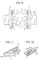
- Figure 8 is an explanatory model diagram of the behaviour of the metal particles in. the circuit breaker of Figures 6(a) and 6(b). Even in a case where surfaces X are formed of contact members, the behaviour of the metal particles does not differ from the ensuing explanation at all.
- a pair of rigid conductors 201 and 301 are constructed in the same shape as in Figure 2, and the arc shields 6 and 7 are respectively mounted on the conductors 201 and 301 in a manner to expose the surfaces X, i.e. the mutually confronting surfaces of the conductors 201 and 301, and to oppose to the arc A.
- the metal particles a and c emitted from the surfaces X are effectively injected into the arc space.
- the metal particles a and c effectively injected in large quantities deprive the arc space of large quantities of energy beyond comparison with those in the prior device, to therefore cool the arc space remarkably.
- the resistivity p or the arc resistance R is raised remarkably, and the arc voltage is raised very greatly.
- the first movable rigid conductor 201 is turnably held on the holder 102 by the pivot pin 103, so that when the arc A has developed immediately after the separation of the first and second contacts 202 and 302, this first conductor 201 is separated from the second movable rigid conductor 301 at very high speed by the forces produced by the pressures of the spaces Q rendered very high owing to the effect of the arc shields 6 and 7. This state immediately after the separation is shown in Figure 9.
- a magnetic material may be employed so as to attract the arc A and to consequently raise the arc voltage; alternatively, a nonmagnetic material may be employed so as to split the arc A and to consequently raise the arc voltage.
- the magnetic material With the magnetic material, the arc A is favorably cooled, but a temperature rise attributed to eddy current due to the magnetic material poses a problem in a circuit breaker of a high rated current. With the nonmagnetic material, this problem is avoided.
- FIGS 10 and 11 are perspective views showing the arc shields.
- Slits or arc runways 601 and 701 are respectively provided in the arc shields 6 and 7 to extend from the first and second contacts 202 and 302 toward the arc extinguishing plates 5, so as to expose the first and second movable rigid conductors 201 and 301.
- the arc A runs toward the arc extinguishing plates 5 within these slits to become effectively extinguished in direct contact with the arc extinguishing plates 5.
- This described embodiment of the circuit breaker according to the invention is adapted to separate the first movable rigid conductor 201 at high speed by mounting the arc shields 6 and 7, so that the arc voltage can be remarkably raised far beyond the limit thereof in the prior circuit breaker, and so that a high current-limiting performance can be attained.
- the circuit it breaker of the present embodiment can prevent the polarity effect on the current-limiting performance from becoming different depending upon whether the polarity on the contact to be separated by the electromagnetic repellence is a cathode or an anode, and it can stabilize the current-limiting performance. That is, such beneficial result is achieved by the measure that both the first rigid conductor 201 and the second rigid conductor 301 on which the first contact 202 and the second contact 302 are respectively mounted are formed of the turnable electromagnetic repulsion type.
Landscapes
- Physics & Mathematics (AREA)
- Electromagnetism (AREA)
- Arc-Extinguishing Devices That Are Switches (AREA)
Description
- Preferred ways of carrying out the invention are described in detail below with reference to drawings, in which:-
- Figure 1a is a sectional plan view of a conventional circuit breaker to which the present invention is applicable,
- Figure 1 b is a sectional side view taken along line b-b in Figure 1a,
- Figure 2 is a model diagram showing the behaviour of an electric arc which is struck across the contacts of the circuit breaker in Figure 1a,
- Figure 3a is a side view showing a known contactor,
- Figure 3b is a plan view of the contactor in Figure 3a,
- Figure 3c is a sectional front view taken along line c-c in Figure 3b,
- Figure 4a is a side view showing in a model fashion the state of an electric arc in the case where the contactor in Figure 3a is used in a circuit breaker,
- Figure 4b is a front view corresponding to Figure 4a,
- Figure 5 is a model diagram showing the behaviour of the arc in Figure 4a,
- Figure 6a is a sectional plan view showing features of an embodiment of a circuit breaker according to the present invention,
- Figure 6b is a sectional side view taken along line b-b in Figure 6a and showing the state in which the contacts of the circuit breaker are disengaged,
- Figure 7 is a sectional side view showing the state in which the contacts of the circuit breaker in Figure 6a are engaged,
- Figure 8 is a model diagram showing the action of arc shields for use in the circuit breaker according to the present invention,
- Figure 9 is a sectional side view showing the state in which the contacts of the circuit breaker in Figure 6a have started to separate,
- Figure 10 is a perspective view of one contactor showing the arc shield for use in the circuit breaker of the present invention,
- Figure 11 is a perspective view of the other contactor which corresponds to the contactor in Figure 10,
- In the drawings, the same symbols indicate identical or corresponding parts.
- Figures 1 (a) and 1 (b) illustrate a conventional circuit breaker. In Figures 1(a) and 1(b), assuming now that a
movable contact 302 of amovable contactor 3 and astationary contact 202 of astationary contactor 2 are closed, current flows along the path from a stationaryrigid conductor 201 to thestationary contact 202, to themovable contact 302 and to a movablerigid conductor 301. - When, under this state, a high current such as short-circuit current flows through the circuit, an
operating mechanism 4 works to separate themovable contact 302 from thestationary contact 202. At this time, an electric arc Aappears across thestationary contact 202 and themovable contact 302, and an arc voltage develops thereacross. The arc voltage rises as the distance of separation of themovable contact 302 from thestationary contact 202 increases. Simultaneously therewith, the arc A is drawn toward arcextinguishing plates 5 by a magnetic force and is stretched, so that the arc voltage rises still further. In this manner, the arc current reaches the current zero point to extinguish the arc A, so that the interruption is completed. During such interrupting operation, large quantities of energy are generated by the arc A across themovable contact 302 and thestationary contact 202 in a short time of several milliseconds. In consequence, the temperature of a gas within an enclosure 1 rises, and also the pressure thereof rises abruptly, but the gas at the high temperature and under the high pressure is emitted into the atmosphere through anexhaust port 101. - In case of the interruption, the circuit breaker and its internal constituent parts perform the operations as described above. Now, the operation of the
stationary contact 202 and themovable contact 302 will be especially explained. In general, the arc resistance R is given by the following expression:

- In general, in a short arc A which has a high current of at least several kA and an arc length / of at most 50 mm, the arc space is occupied by the ,metal particles of rigid conductors with arc feet (bases) existing on their surfaces. Moreover, the emission of the metal particles occurs orthogonally to the conductor surfaces. At the emission, the emitted metal particles have a temperature close to the boiling point of the metal of the rigid conductors. Further, as soon as the metal particles are injected into the arc space, they are supplied with electrical energy to be raised in temperature and pressure and to bear a conductivity, and they flow away from the rigid conductors at high speed while expanding in a direction conforming with the pressure distribution of the arc space. The arc resistivity p and the arc sectional area S in the arc space are determined by the quantity of the metal particles produced and the direction of emission thereof. Accordingly, the arc voltage is determined by the behaviour of such metal particles. Next, the behaviour of such metal particles will be described with reference to Figure 2. Even when surfaces X are constructed of contact members, the behaviour of metal particles to be described below holds quite similarly.
- Referring to Figure 2, a pair of
rigid conductors rigid conductor 201 is an anode, while therigid conductor 301 is a cathode. The surfaces X of therespective conductors conductors respective conductors rigid conductors conductors - Such metal particles a and b emitted from the
conductors conductors - Further, the paths of the metal particles a and b emitted from the
conductors - The pressure of the arc space is determined by the mutual relationship between the pinch force of the current itself and the thermal expansion of the metal particles a and b. The pinch force is a quantity which is substantially determined by the density of the current. In other words, it is determined by the size of the foot of the arc A on the
conductors - It is also known that, in case the feet of the arc A on the
conductors conductor 301 against theother conductor 201 in the form of vapor jet. When, in this manner, the metal particles a fly unidirectionally from the oneconductor 301 toward theother conductor 201, the metal particles a to be injected into the positive column of the arc A are supplied substantially from only the conductor on oneside 301. While Figure 2 illustrates by way of example the case where the metal particles are flying strongly from the cathode against the anode, they sometimes fly in the opposite direction. - The above circumstances will now be described. In Figure 2, it is supposed that the metal particles fly unidirectionally from the
conductor 301 toward theconductor 201 for any reason. The metal particles a starting from the surface X, the opposing surface ofconductor 301, tend to fly orthogonally to the conductor surface, i.e. toward the positive column of the arc. At this time, the metal particle a having started from the surface X of oneconductor 301 is injected into the positive column by the pressure caused by the pinch force. In contrast, the metal particle a having started from the surface X of theother conductor 201 is pushed by the particle stream in the positive column and ejected outside the surface X, and it is immediately forced out of the system without entering the positive column. In this manner, the movement of the metal particle a emitted from theconductor 201 and that of the metal particle a emitted from theconductor 301 are different as indicated by the flow lines of the arrows m and m' in Figure 2. As stated before, this is based on the difference between the pressures caused by the pinch forces on the conductor surfaces. Thus, the unidirectional blow from theconductor 301 heats theconductor 201 on the blown side and expands the foot (anode spot or cathode spot) of the arc on the surface of theconductor 201 from the front surface X thereof to the other surface thereof. In consequence, the current density on the conductor surface of theconductor 201 lowers, same as the pressure of the arc. Accordingly, the unidirectional blow from theconductor 301 is increasingly intensified. The discrepancy of the flight paths of the metal particles a emitted from therespective conductors conductor 301 can absorb energy from the positive column sufficiently, whereas the metal particle a having started from the surface X of theconductor 201 cannot absorb energy sufficiently and is ejected out of the system without cooling the arc A effectively. On the other hand, the metal particles b emitted from the surfaces Y of therespective conductors - In this manner, in the presence of the blow from one
conductor 301, the efficiency of the cooling of the positive column by the metal particles a is impaired. In addition, the metal particles b emitted from the non- opposing surfaces Y of bothconductors - Accordingly, the presence of the unidirectional blow of the metal particles from one conductor to the other is disadvantageous for raising the arc voltage and renders it impossible to enhance the current-limiting performance at the tripping.
- In general, the stationary rigid contactor and the movable rigid contactor used in the conventional circuit breaker are large in the surface area of the opposing surfaces, similarly to the rigid conductors of the model of Figure 2, so that they cannot limit the size of the foot of the struck arc, disadvantageously. Moreover, the contactors have the exposed surfaces such as side surfaces besides the opposing surfaces, so that as explained with reference to Figure 2, the position and size of the feet (anode spot and cathode spot) of the arc appearing on the surfaces of both conductors cannot be limited. In the mechanism explained with reference to Figure 2, accordingly, the unidirectional blow of the metal particles a from one contactor against the other contactor proceeds and therefore the arc sectional area increases, so that as stated above, the currentlimiting performance at the tripping cannot be enhanced.
- As an example of another contactor used in a prior circuit breaker, there has been one in which the part of a conductor suface adjacent to a contact is covered with an
insulator 11 in order to prevent the fusion of a conductor to the area around the contact. Figures 3(a) to 3(c) showsuch contactor 2. In the example shown, the fore end part of the conductor is not covered with theinsulator 11. - In a circuit breaker constructed as shown in Figures 4(a) and 4(b) and including a pair of rigid conductors of such construction, an electric arc A as illustrated in these Figures develops across the paired
stationary contactor 2 andmovable contactor 3. In the arc A, its feet or the positions of an anode spot and a cathode spot flare greatly toward the fore ends of the rigid conductors as appears from Figures 4(a) and (b), so there has been the disadvantage that the current- limiting performance at the tripping cannot be enhanced for the same reason as explained with reference to Figure 2. Further, regarding a case where, as shown in Figure 5, only one of a pair of contacts is provided with a coating which has a plate-shapedmember 11 of an insulator covering the peripheral part of the contacting surface thereof, the state of the surface has been examined. In this example, metal particles a the flowing in confined directions are injected into an arc positive column portion from the surface X of arigid conductor 302 which has the contact enclosed with theinsulator 11. However, as regards metal particles from the surface X of arigid conductor 201 which has the contact not coated with theinsulator 11, the foot of an arc or the anode spot or cathode spot thereof spreads on the whole conductor surface without being limited, and further spreads to surfaces Y, i.e. the side surfaces of the contact, so that the current density decreases. It is accordingly the same as in Figure 2 that the pinch force weakens and that the metal particles run out of the arc. Therefore, even when the insulator is disposed in the vicinity of one conductor, the aspect of the arc positive column portion eventually becomes the phenomenon of the unidirectional blow of the metal particles. Accordingly, both conductors are subject to the same circumstances as in the case where the size of the foot of the arc is not limited, and the arc voltage does not show any especially great rise, so that the current- limiting performance is not enhanced. - As explained above, in order to raise the arc voltage, the metal particles having appeared in the feet of the arc need to be effectively injected into the positive column from both electrodes. The force which injects the metal particles into the positive column is the pressure based on the pinch force arising in the foot of the arc. Since the pinch force changes greatly depending upon the size of the foot of the arc on the contactor or upon the current density, it can be controlled. For example, in the conventional contactors, the area of the surface X of at least one contactor is large, and it does not limit the size of the foot of the arc to an effective degree. Even in such contactors employing no insulator, however, when the opposing surfaces X of both contactors are made sufficiently small, the density of current on the surfaces X rises to some extent, to increase the pinch forces, and the metal particles of the respective contactors are injected from both sides into the positive column to some extent, unlike the situations of the prior devices, whereby the arc voltage becomes higher than in the prior devices.
- Merely with this measure, however, the spread of the foot of the arc to the other parts than the surfaces X or to the surfaces Y cannot be checked, and the current density on the surfaces X decreases by a component corresponding to the spread of the foot of the arc to the surfaces Y, so that the injection pressure of the metal particles lowers. In the case of the conventional contactors, accordingly, the effect of cooling the positive column by the metal particles is not obtained to maximum degree.
- Further, the serious disadvantage of the conventional contactors is that, on account of the spread of the foot of the arc to the surface Y, the foot of the arc is liable to spread directly to the joint part between the contact and the conductor as is usually set on the surface Y, so the joint member of low fusing point is melted by the heat of the arc, the contact being prone to fall off.
- In EP-A-0 059 455 (which lies within the terms of Article 54(3) EPC) a circuit breaker is described showing arc shields of the kind described, whereby this breaker forms a current loop in the closed state by the arrangement of its contactor arms. For separating the two contacts by magnetic repulsion force very rapidly a flux board is provided, which is arranged laterally of the two contactor arms and which collects the magnetic flux at its side parts.
- However, it may happen under certain circumstances that due to the inertia of the operation mechanism or the inertia of the contactor arms themselves rapid increase of arc voltage and thus rapid extinction of the arc cannot be obtained, whereby early wear of the contacts takes place.
- In the circuit breaker according to the invention as defined by Claim 1, arc shields are disposed on said contactor arms in a way as to surround the respective contacts, the first contactor arm is pivotally mounted on the enclosure and provided with a spring urging the contactor arm into direction towards the second contactor arm,
- the second contactor arm is also pivotally mounted on the enclosure and additionally pivotally connected with the operation mechanism,
- and these contactor arms are arranged relative to each other in a way, that only such portions which are adjacent the contacts (2, 3) or the respective arc shields (6, 7) are facing each other in the closed state.
- The arc shields are made of highly resistive material (called the "high resistivity material" hereinbelow) having a resistivity higher than that of a material forming the rigid conductor, thereby to forci bly inject metal particles into an arc space, and the electrodes are separated at high speed by a high pressure established owing to the provision of the arc shield.
- As high-resistivity material, there can be used, for example for, an organic and inorganic insulator, or a high-resistivity metal such as copper-nickel, copper-manganese, manganin, ironcarbon, iron-nickel and iron chromium. It is also possible to use iron whose resistance increases in accordance to the temperature rise.
- As operating mechanism a conventional operating mechanism as for example disclosed in the US-Patent 3,171,922 can be used to operate the respective contactor arms in order to close or open the circuit breaker according to the present invention.
- Furthermore at least one of the arc shields is provided with a slit or arc run way (601, 701), extending from the first or second contact towards arc exten- guishing plates and exposing the respective conductor whereby the arc is forced towards the arc extinguishing plates within the slit(s) and effective extinguishment in direct contact with the arc extinguishing plates can be realised.
- By the technical teaching of the present invention the contacts can be separated at very high speed by a high pressure. This results in a high arc voltage and a good current-limiting performance at the tripping, early wear of the contacts can be avoided.
- Figures 6(a) and 6(b) illustrate features of the circuit breaker according to this invention. In Figures 6(a) and 6(b), an enclosure 1 made of an insulator forms the outer frame of a switching device and is provided with an
exhaust port 101. A first movable contactor (arm) 2 comprises a first movablerigid conductor 201 with the part intermediate its ends being turnably pivotally supported by apivot pin 103 on aholder 102 that is fixed to the enclosure 1, as well as afirst contact 202 which is mounted to one end part of thefirst conductor 201. Asecondmovable contactor 3 comprises a second movablerigid conductor 301 which moves relative to the first movablerigid conductor 201 in order to close or open the circuit breaker, and asecond contact 302 which is mounted on one end part of thesecond conductor 301 in a manner to confront thefirst contact 202. Aconventional operating mechanism 4 operates the secondmovable contactor 3 relative to the firstmovable contactor 2 in order to close or open the circuit breaker (compare e.g. U.S.-A-3,171,922). In the present embodiment, this mechanism comprises asupporter 402 which turnably (pivotally) supports the other end part of the second movablerigid conductor 301 by means of apivot pin 401, a lower Iink404 one end part of which is turnably mounted to the intermediate or central part of the second movablerigid conductor 301 by apivot pin 403, anupper link 406 one end of which is turnably mounted to the other end part of the lower link 404 by apivot pin 405, and anoperating handle 407 which is turnably mounted to the other end part of theupper link 406 by a pivot pin (not shown).Arc extinguishing plates 5 which extinguish an electric arc struck when thesecond contact 302 is separated from thefirst contact 202, are supported by a pair ofside plates rigid conductors second contacts spring 8 being interposed between the enclosure 1 and the first movablerigid conductor 201 urges thefirst contact 202 against thesecond contact 302. Aconnection terminal 9 is connected to the first movablerigid conductor 201 through aflexible conductor 10, and also to an external conductor (not shown). - Now, when the
operating handle 407 is turned clockwise according to Figure 6(b), the linkage composed of the upper andlower links 406 and 404 operates to engage the first andsecond contacts connection terminal 9, toflexible conductor 10, to first movablerigid conductor 201, tofirst contact 202, tosecond contact 302 and to second movable rigid conductor301. When, under this state, a high current, such as a short-circuit current, flows through the circuit, thesecond contact 302 is separated from thefirst contact 202 by an electromagnetic repulsive force based on current concentration in the contacing points of thecontacts first contact 202 and thesecond contact 302. As illustrated in Figure 8, metal particles are reflected in the arc by the arc shields 6 and 7 to render the pressure of the arc space high, with the result that the separation of the contacts is promoted and that the arc is effectively cooled. - Figure 8 is an explanatory model diagram of the behaviour of the metal particles in. the circuit breaker of Figures 6(a) and 6(b). Even in a case where surfaces X are formed of contact members, the behaviour of the metal particles does not differ from the ensuing explanation at all. In Figure 8, a pair of
rigid conductors conductors conductors - Further, when the arc shields 6 and 7 are installed closely around the contacting surfaces of the
first contact 202 and thesecond contact 302 as shown by way of example in Figures 6(a) and 6(b), i.e. the opposing surfaces X according to Figure 8, the arc A is prevented from moving to the conductor surfaces Y, so that the size of the feet of the arc A is also limited. For this reason, the generation of the metal particles a and c can be concentrated on the surfaces X, and also the arc sectional area S can be reduced whereby the effective injection of the metal particles a and c into the arc space can be further promoted. Accordingly, the cooling of the arc space, the rise of the arc resistivity p and the rise of the arc resistance R are further promoted, and the arc voltage can be raised further. - The first movable
rigid conductor 201 is turnably held on theholder 102 by thepivot pin 103, so that when the arc A has developed immediately after the separation of the first andsecond contacts first conductor 201 is separated from the second movablerigid conductor 301 at very high speed by the forces produced by the pressures of the spaces Q rendered very high owing to the effect of the arc shields 6 and 7. This state immediately after the separation is shown in Figure 9. More specifically, before the open state shown in Figure 6(b) is established, the second movablerigid conductor 301 can have only a comparatively low separating speed on account of the inertia of theoperating mechanism 4, whereas the first movablerigid conductor 201 has the very high separating speed owing to the pressure of the space Q. Therefore, the rise of the arc voltage immediately after the separation of the first andsecond contacts - For the
arc extinguishing plates 5, a magnetic material may be employed so as to attract the arc A and to consequently raise the arc voltage; alternatively, a nonmagnetic material may be employed so as to split the arc A and to consequently raise the arc voltage. With the magnetic material, the arc A is favorably cooled, but a temperature rise attributed to eddy current due to the magnetic material poses a problem in a circuit breaker of a high rated current. With the nonmagnetic material, this problem is avoided. - Figures 10 and 11 are perspective views showing the arc shields. Slits or
arc runways second contacts arc extinguishing plates 5, so as to expose the first and second movablerigid conductors slits arc extinguishing plates 5 within these slits to become effectively extinguished in direct contact with thearc extinguishing plates 5. - This described embodiment of the circuit breaker according to the invention is adapted to separate the first movable
rigid conductor 201 at high speed by mounting the arc shields 6 and 7, so that the arc voltage can be remarkably raised far beyond the limit thereof in the prior circuit breaker, and so that a high current-limiting performance can be attained. - In a circuit breakerfor alternating current, the polarity of the current on a contact during arcing is not decided, and moreover, the polarity on the same contact changes even during arcing. In this regard, the circuit it breaker of the present embodiment can prevent the polarity effect on the current-limiting performance from becoming different depending upon whether the polarity on the contact to be separated by the electromagnetic repellence is a cathode or an anode, and it can stabilize the current-limiting performance. That is, such beneficial result is achieved by the measure that both the first
rigid conductor 201 and the secondrigid conductor 301 on which thefirst contact 202 and thesecond contact 302 are respectively mounted are formed of the turnable electromagnetic repulsion type.
Claims (4)
characterized in that are shields (6, 7) are disposed on the contactor arms (2, 3) in such a way as to surround the respective contacts (202, 302) and that at least one of said arc shields (6, 7) is provided with a slit (601 or 701) extending from the contact (202, 302) towards the arc extinguishing plates (5) and exposing the respective contactor arm (2, 3).
Priority Applications (1)
| Application Number | Priority Date | Filing Date | Title |
|---|---|---|---|
| DE8282102015T DE3278958D1 (en) | 1981-03-12 | 1982-03-12 | Circuit breaker |
Applications Claiming Priority (10)
| Application Number | Priority Date | Filing Date | Title |
|---|---|---|---|
| JP3555781U JPS57147553U (en) | 1981-03-12 | 1981-03-12 | |
| JP3555281U JPS57147548U (en) | 1981-03-12 | 1981-03-12 | |
| JP35554/81U | 1981-03-12 | ||
| JP35552/81U | 1981-03-12 | ||
| JP3555681U JPS57147552U (en) | 1981-03-12 | 1981-03-12 | |
| JP35555/81U | 1981-03-12 | ||
| JP35557/81U | 1981-03-12 | ||
| JP35556/81U | 1981-03-12 | ||
| JP3555581U JPS57147551U (en) | 1981-03-12 | 1981-03-12 | |
| JP1981035554U JPH0218516Y2 (en) | 1981-03-12 | 1981-03-12 |
Related Child Applications (4)
| Application Number | Title | Priority Date | Filing Date |
|---|---|---|---|
| EP86115278.3 Division-Into | 1986-11-04 | ||
| EP86115277.5 Division-Into | 1986-11-04 | ||
| EP86115269.2 Division-Into | 1986-11-04 | ||
| EP86115283.3 Division-Into | 1986-11-04 |
Publications (4)
| Publication Number | Publication Date |
|---|---|
| EP0061097A2 EP0061097A2 (en) | 1982-09-29 |
| EP0061097A3 EP0061097A3 (en) | 1983-07-27 |
| EP0061097B1 EP0061097B1 (en) | 1988-08-24 |
| EP0061097B2 true EP0061097B2 (en) | 1992-08-05 |
Family
ID=27521712
Family Applications (1)
| Application Number | Title | Priority Date | Filing Date |
|---|---|---|---|
| EP82102015A Expired EP0061097B2 (en) | 1981-03-12 | 1982-03-12 | Circuit breaker |
Country Status (3)
| Country | Link |
|---|---|
| US (1) | US4464642A (en) |
| EP (1) | EP0061097B2 (en) |
| DE (4) | DE3280339D1 (en) |
Families Citing this family (4)
| Publication number | Priority date | Publication date | Assignee | Title |
|---|---|---|---|---|
| FR2969366B1 (en) * | 2010-12-20 | 2013-03-01 | Schneider Electric Ind Sas | ARM CUT SCREEN CUTTING DEVICE |
| US8445803B1 (en) * | 2011-11-28 | 2013-05-21 | Itron, Inc. | High power electrical switching device |
| JP6136597B2 (en) * | 2013-06-06 | 2017-05-31 | 株式会社明電舎 | Sealed relay |
| US20150069021A1 (en) * | 2013-09-11 | 2015-03-12 | Siemens Industry, Inc. | Apparatus and method for reducing electrical arcing in a circuit breaker while transitioning to a closed circuit condition |
Family Cites Families (12)
| Publication number | Priority date | Publication date | Assignee | Title |
|---|---|---|---|---|
| US3127488A (en) * | 1960-07-18 | 1964-03-31 | Ite Circuit Breaker Ltd | Current limiting circuit breaker having both contacts movable |
| CH403075A (en) * | 1963-09-27 | 1965-11-30 | Bbc Brown Boveri & Cie | Step switching device for regulating transformers |
| US3402273A (en) * | 1965-12-01 | 1968-09-17 | Ite Circuit Breaker Ltd | Arc chamber for circuit breakers |
| US3469216A (en) * | 1966-07-12 | 1969-09-23 | Nikko Electric Mfg Co Ltd | High speed current limiting circuit breaker utilizing electromagnetic repulsion |
| US3464038A (en) * | 1967-02-16 | 1969-08-26 | Terasaki Denki Sangyo Kk | Circuit interrupter |
| FR1585120A (en) * | 1967-07-24 | 1970-01-09 | ||
| DE1765050B2 (en) * | 1968-03-26 | 1976-08-05 | Deutsche Gold- Und Silber-Scheideanstalt Vormals Roessler, 6000 Frankfurt | ELECTRICAL CONTACT OR ELECTRODE ARRANGEMENT FOR THE FIXED STABILIZATION OF THE ARC FLOOR POINTS AND TO REDUCE THE BURN-ON LOSS |
| JPS492468B1 (en) * | 1968-07-15 | 1974-01-21 | ||
| US3500266A (en) * | 1968-08-01 | 1970-03-10 | Federal Pacific Electric Co | High-speed circuit breakers |
| US3997746A (en) * | 1974-04-23 | 1976-12-14 | Airpax Electronics, Incorporated | Circuit breaker with arc chamber screen |
| JPS5848979B2 (en) * | 1978-08-10 | 1983-11-01 | 富士電機株式会社 | circuit break |
| US4409445A (en) * | 1980-12-09 | 1983-10-11 | Mitsubishi Denki Kabushiki Kaisha | Circuit breaker |
-
1982
- 1982-03-08 US US06/356,144 patent/US4464642A/en not_active Expired - Lifetime
- 1982-03-12 DE DE8686115277T patent/DE3280339D1/en not_active Expired - Lifetime
- 1982-03-12 DE DE8686115283T patent/DE3280367D1/en not_active Expired - Lifetime
- 1982-03-12 DE DE8686115278T patent/DE3280353D1/en not_active Expired - Lifetime
- 1982-03-12 EP EP82102015A patent/EP0061097B2/en not_active Expired
- 1982-03-12 DE DE8686115269T patent/DE3280351D1/en not_active Expired - Lifetime
Also Published As
| Publication number | Publication date |
|---|---|
| DE3280367D1 (en) | 1991-11-21 |
| DE3280351D1 (en) | 1991-10-02 |
| EP0061097A3 (en) | 1983-07-27 |
| EP0061097A2 (en) | 1982-09-29 |
| EP0061097B1 (en) | 1988-08-24 |
| DE3280339D1 (en) | 1991-07-04 |
| DE3280353D1 (en) | 1991-10-02 |
| US4464642A (en) | 1984-08-07 |
Similar Documents
| Publication | Publication Date | Title |
|---|---|---|
| EP0059476B1 (en) | Circuit breaker | |
| EP0070413B2 (en) | A circuit breaker with arc restricting device | |
| EP0061097B2 (en) | Circuit breaker | |
| EP0054833B1 (en) | Arc restricting device for a circuit breaker | |
| US4409444A (en) | Circuit breaker | |
| EP0059455B1 (en) | Arc restricting device for circuit breaker | |
| EP0232473A2 (en) | A circuit breaker | |
| EP0233323A2 (en) | A circuit breaker | |
| EP0233322A2 (en) | A circuit breaker | |
| EP0237623A1 (en) | A circuit breaker | |
| EP0061006B2 (en) | Arc restricting device for circuit breaker | |
| EP0057452B1 (en) | Arc restricting device for a circuit breaker | |
| JPH0113316Y2 (en) | ||
| JPH0218513Y2 (en) | ||
| KR880001790Y1 (en) | Circuit breaker | |
| JPH0218512Y2 (en) | ||
| CA1303653C (en) | Current limiting circuit interrupter | |
| JPH0218516Y2 (en) | ||
| JPH0218515Y2 (en) | ||
| JPH0113314Y2 (en) | ||
| JPH0113315Y2 (en) | ||
| JPH0126028Y2 (en) | ||
| JPH0236204Y2 (en) | ||
| JPH0218517Y2 (en) | ||
| JPS6337928B2 (en) |
Legal Events
| Date | Code | Title | Description |
|---|---|---|---|
| PUAI | Public reference made under article 153(3) epc to a published international application that has entered the european phase |
Free format text: ORIGINAL CODE: 0009012 |
|
| AK | Designated contracting states |
Designated state(s): CH DE FR GB IT LI |
|
| PUAL | Search report despatched |
Free format text: ORIGINAL CODE: 0009013 |
|
| 17P | Request for examination filed |
Effective date: 19830309 |
|
| AK | Designated contracting states |
Designated state(s): CH DE FR GB IT LI |
|
| GRAA | (expected) grant |
Free format text: ORIGINAL CODE: 0009210 |
|
| AK | Designated contracting states |
Kind code of ref document: B1 Designated state(s): CH DE FR GB IT LI |
|
| ITF | It: translation for a ep patent filed | ||
| REF | Corresponds to: |
Ref document number: 3278958 Country of ref document: DE Date of ref document: 19880929 |
|
| ET | Fr: translation filed | ||
| PLBI | Opposition filed |
Free format text: ORIGINAL CODE: 0009260 |
|
| 26 | Opposition filed |
Opponent name: SIEMENS AKTIENGESELLSCHAFT, BERLIN UND MUENCHEN Effective date: 19890523 |
|
| ITTA | It: last paid annual fee | ||
| PUAH | Patent maintained in amended form |
Free format text: ORIGINAL CODE: 0009272 |
|
| STAA | Information on the status of an ep patent application or granted ep patent |
Free format text: STATUS: PATENT MAINTAINED AS AMENDED |
|
| 27A | Patent maintained in amended form |
Effective date: 19920805 |
|
| AK | Designated contracting states |
Kind code of ref document: B2 Designated state(s): CH DE FR GB IT LI |
|
| ITF | It: translation for a ep patent filed | ||
| REG | Reference to a national code |
Ref country code: CH Ref legal event code: AEN |
|
| ET3 | Fr: translation filed ** decision concerning opposition | ||
| PGFP | Annual fee paid to national office [announced via postgrant information from national office to epo] |
Ref country code: CH Payment date: 19950315 Year of fee payment: 14 |
|
| REG | Reference to a national code |
Ref country code: GB Ref legal event code: 746 Effective date: 19951026 |
|
| REG | Reference to a national code |
Ref country code: FR Ref legal event code: D6 |
|
| PG25 | Lapsed in a contracting state [announced via postgrant information from national office to epo] |
Ref country code: LI Effective date: 19960331 Ref country code: CH Effective date: 19960331 |
|
| ITPR | It: changes in ownership of a european patent |
Owner name: OFFERTA DI LICENZA AL PUBBLICO |
|
| REG | Reference to a national code |
Ref country code: CH Ref legal event code: PL |
|
| PGFP | Annual fee paid to national office [announced via postgrant information from national office to epo] |
Ref country code: FR Payment date: 19990309 Year of fee payment: 18 |
|
| PGFP | Annual fee paid to national office [announced via postgrant information from national office to epo] |
Ref country code: GB Payment date: 19990311 Year of fee payment: 18 |
|
| PGFP | Annual fee paid to national office [announced via postgrant information from national office to epo] |
Ref country code: DE Payment date: 19990319 Year of fee payment: 18 |
|
| PG25 | Lapsed in a contracting state [announced via postgrant information from national office to epo] |
Ref country code: GB Free format text: LAPSE BECAUSE OF NON-PAYMENT OF DUE FEES Effective date: 20000312 |
|
| GBPC | Gb: european patent ceased through non-payment of renewal fee |
Effective date: 20000312 |
|
| PG25 | Lapsed in a contracting state [announced via postgrant information from national office to epo] |
Ref country code: FR Free format text: LAPSE BECAUSE OF NON-PAYMENT OF DUE FEES Effective date: 20001130 |
|
| REG | Reference to a national code |
Ref country code: FR Ref legal event code: ST |
|
| PG25 | Lapsed in a contracting state [announced via postgrant information from national office to epo] |
Ref country code: DE Free format text: LAPSE BECAUSE OF NON-PAYMENT OF DUE FEES Effective date: 20010103 |
|
| APAH | Appeal reference modified |
Free format text: ORIGINAL CODE: EPIDOSCREFNO |