EP0060949B1 - Apparatus for the manufacture of fibrous webs and method therefor - Google Patents
Apparatus for the manufacture of fibrous webs and method therefor Download PDFInfo
- Publication number
- EP0060949B1 EP0060949B1 EP81301273A EP81301273A EP0060949B1 EP 0060949 B1 EP0060949 B1 EP 0060949B1 EP 81301273 A EP81301273 A EP 81301273A EP 81301273 A EP81301273 A EP 81301273A EP 0060949 B1 EP0060949 B1 EP 0060949B1
- Authority
- EP
- European Patent Office
- Prior art keywords
- forming wire
- planar section
- suction box
- movement
- wire
- Prior art date
- Legal status (The legal status is an assumption and is not a legal conclusion. Google has not performed a legal analysis and makes no representation as to the accuracy of the status listed.)
- Expired
Links
Images

Classifications
-
- D—TEXTILES; PAPER
- D04—BRAIDING; LACE-MAKING; KNITTING; TRIMMINGS; NON-WOVEN FABRICS
- D04H—MAKING TEXTILE FABRICS, e.g. FROM FIBRES OR FILAMENTARY MATERIAL; FABRICS MADE BY SUCH PROCESSES OR APPARATUS, e.g. FELTS, NON-WOVEN FABRICS; COTTON-WOOL; WADDING ; NON-WOVEN FABRICS FROM STAPLE FIBRES, FILAMENTS OR YARNS, BONDED WITH AT LEAST ONE WEB-LIKE MATERIAL DURING THEIR CONSOLIDATION
- D04H1/00—Non-woven fabrics formed wholly or mainly of staple fibres or like relatively short fibres
- D04H1/70—Non-woven fabrics formed wholly or mainly of staple fibres or like relatively short fibres characterised by the method of forming fleeces or layers, e.g. reorientation of fibres
- D04H1/72—Non-woven fabrics formed wholly or mainly of staple fibres or like relatively short fibres characterised by the method of forming fleeces or layers, e.g. reorientation of fibres the fibres being randomly arranged
- D04H1/732—Non-woven fabrics formed wholly or mainly of staple fibres or like relatively short fibres characterised by the method of forming fleeces or layers, e.g. reorientation of fibres the fibres being randomly arranged by fluid current, e.g. air-lay
-
- D—TEXTILES; PAPER
- D04—BRAIDING; LACE-MAKING; KNITTING; TRIMMINGS; NON-WOVEN FABRICS
- D04H—MAKING TEXTILE FABRICS, e.g. FROM FIBRES OR FILAMENTARY MATERIAL; FABRICS MADE BY SUCH PROCESSES OR APPARATUS, e.g. FELTS, NON-WOVEN FABRICS; COTTON-WOOL; WADDING ; NON-WOVEN FABRICS FROM STAPLE FIBRES, FILAMENTS OR YARNS, BONDED WITH AT LEAST ONE WEB-LIKE MATERIAL DURING THEIR CONSOLIDATION
- D04H1/00—Non-woven fabrics formed wholly or mainly of staple fibres or like relatively short fibres
- D04H1/70—Non-woven fabrics formed wholly or mainly of staple fibres or like relatively short fibres characterised by the method of forming fleeces or layers, e.g. reorientation of fibres
- D04H1/72—Non-woven fabrics formed wholly or mainly of staple fibres or like relatively short fibres characterised by the method of forming fleeces or layers, e.g. reorientation of fibres the fibres being randomly arranged
- D04H1/736—Non-woven fabrics formed wholly or mainly of staple fibres or like relatively short fibres characterised by the method of forming fleeces or layers, e.g. reorientation of fibres the fibres being randomly arranged characterised by the apparatus for arranging fibres
Definitions
- This invention relates to improvements in apparatus and methods for the manufacture of fibrous webs, such as paper and the like. More particularly, but not exclusively, the invention is directed to improvements in the manufacture of tissue by the air-laying principle.
- Air laid fibrous webs have an undesirable tendency to form ripples that extend transversely of the forming wire whereby the web is weakened in the machine direction. These ripples form when attempts are made to operate at economical, high forming wire velocities in excess of a range from about 500 feet per minute (2.54 meters per second) to about 550 feet per minute (2.79 m/sec) and at economical air velocities in a range of from about 250 to about 300 feet per minute (1.27 to 1.52 m/sec) through the forming wire. The ripples do not tend to form at lesser forming wire velocities.
- U.S. Patent No. 4,004,323 discloses, in Figure 2, a formation duct disposed at an angle of incidence to a linear foraminous forming surface, the angle being in a range of from about 10 degrees to about 30 degrees, most preferably about 20 degrees.
- the patent further discloses that front and rear inner surfaces may be divergent at an angle of about 1 1/2 degrees, but preferably tQpt they be parallel; and that the forming surface speed may be in excess of 200 feet per minute (1.01 m/sec) or even more than 400 feet per minute (2.03 m/s). The velocity of air through the forming surface, the relative velocity of the fibers with respect to the forming surface in the direction of movement of the latter, and their practical importance in successful air laying are ignored.
- U.S. Patent No. 4,035,870 discloses a fiber conduit and a forming bell coaxially aligned along an axis disposed at an acute angle to the forming surface of a wire so that fibers are deposited on surface in a direction having a vector component coinciding with the direction of movement of surface 16.
- U.S. Patent No. 3,748,693 discloses vanes in a suction box having upstream and downstream air outlets.
- the vanes extend transversely of the direction of movement of a forming wire and are selectively adjustable to differentially restrict air flow through the wire so as to vary web thickness.
- the invention provides a method for forming dry fibers into a fibrous web substantially devoid of transverse ripples, comprising directing fibers in an inclined stream onto a planar section of a moving forming wire, characterised by moving the wire at a velocity in excess of 500 feet per minute (2.54 m/sec), maintaining the angle of impingement of the said stream on the planar section in a range from 21 to 30 degrees, and maintaining a pressure drop through the said planar section by causing air to flow therethrough at a velocity normal to the planar section in excess of 250 feet per minute (1.27 m/sec).
- the invention provides apparatus comprising a dry fibers distributor means a forming wire having a planar section disposed beneath the distributor means and linearly movable at a velocity in excess of about 500 feet per minute (2.54 m/sec), and a suction box disposed beneath the said planar section to draw air through the forming wire with a velocity component normal to the said planar section in excess of about 250 feet per minute (1.27 m/sec), the apparatus further including an array of parallel, mutually equally spaced vanes or baffles extending transversely of the said planar section, the vanes being located between the distributor means and the planar section and each being disposed obliquely to the planar section to cooperate with the suction box in directing the flow of fibers from the distributor means in the direction of movement of the forming wire at an acute angle in the range of 21 to 30 degrees to the said planar section.
- each vane comprises a segment of a hollow circular cylinder so positioned that a tangent to its upper edge is substantially parallel to the flow of air and fibers from the distributor means and a tangent to its lower edge is substantially parallel to the planar section.
- the alternative baffle is a plate which extends across a bottom opening provided in the distributor means in a direction transverse to the direction of movement of the forming wire and each plate is planar and is inclined downwardly in the direction of the said movement at an angle in the range from 21 to 30 degrees to the forming wire.
- the apparatus comprises a dry fibers distributor means, a forming wire having a planar section disposed beneath the distributor means and linearly movable at a velocity in excess of about 500 feet per minute (2.54 m/sec), and a suction box disposed beneath the said planar section to draw air through the forming wire at a velocity normal to the said planar section in excess of about 250 feet per minute (1.27 m/sec), the apparatus further including baffle means operative to provide fibers leaving the distributor means with a velocity component in the direction of movement of the wire, such that the fibers impinge on the wire at angles in the range of 21 to 30 degrees, the baffle means extending transverse to the forming wire movement horizontally over the upstream region of an upper, horizontally extending opening provided in the suction box beneath the forming wire, the baffle means including a free edge portion facing in the said direction of movement, and an imaginary line extending between an upstream edge of said distributor means and the free edge portion of
- Figure 1 shows an apparatus 10 for forming a web of fibrous material, the apparatus comprising a set of dry fiber distributors 11 each including an impeller one of which is seen at 19.
- the impellers 19 are positioned above a horizontally-extending planar section of a forming wire 12 that is supported for movement on suitably mounted rollers 13 and 14 rotatable for movement of the upper flight of the forming wire in the direction of arrow A.
- the forming wire 12 in use travels at a predetermined velocity V,.
- Suction boxes 15 are disposed beneath forming wire 12, and each is offset at its right-hand, trailing edge in the downstream direction of movement of the wire (i.e., the "machine direction") with respect to the corresponding edge of the distributor 11.
- a pair of parallel deckles or side plates are provided along the sides of forming wire 12 at each distributor 11, only one plate 20 of each pair being shown.
- a blower 16 has its inlet 16a connected to suction boxes 15 and its discharge 16b exits to atmosphere. Blower 16 is operative to create an air flow downwardly through the horizontal, upper flight section of the forming wire 12, the air flow being normal thereto, and at a velocity V 2 , which is about 250 feet per minute or preferably in excess of 250 feet per minute (1.27 m/sec).
- An array of arcuate vanes 17 extends across the bottom opening 11a of each of the distributors 11 between plates 20. Vanes 17 of each array are parallel, are mutually equally spaced and extend transversely of the direction of movement A of the forming wire 12.
- Each vane 17 is a 90° segment of a hollow right circular cylinder, and is so positioned that the tangent to the upper edge is substantially perpendicular to the plane of opening 11a, i.e. substantially parallel to the flow of air and fibers from the distributor, and the tangent to the lower edge is substantially parallel to the direction of movement of the forming wire, and spaced preferably about 1/4 inch (6.3 mm) above the latter.
- the vanes are spaced one from the other so that the tangent T to the upper edge of one vane intersects the lower edge region of the next upstream vane, i.e. the next vane to the left as viewed in Fig. 1.
- the above-described trailing edge offset portion of suction boxes 15, in combination with the shape and disposition of vanes 17, is such as to impart a horizontal velocity componet V 3 to the air, and to the air-entrained fibers flowing between the bottom openings 11a of distributors 11 and the surface of forming wire 12 via the spaces between the vanes 17.
- Ambient air drawn in at S enhances the horizontal component V 3
- ambient air drawn in at S' aids in holding the web on the forming wire. This will be the case for the several embodiments where indicated.
- the horizontal velocity component V 3 is less than the velocity V, of the forming wire, the latter being preferably in excess of about 500 feet per minute (2.54 m/sec).
- the amount of offset is such as to create an air and dry-fiber flow (from openings 11 a to the forming wire 12) which extends downwardly and in the direction of travel of the forming-wire at an angle H in a range of from 21 degrees to 30 degrees measured from the horizontally extending upper flight of the forming wire.
- Such an acute angle of fiber impingement on the wire 12 is based on the finding that successful web formation, free of ripples extending transversely of the forming wire (i.e.,across its width and across the machine direction) is achieved if the ratio of the total magnitude of the tangential velocity relative to the forming wire 12 (i.e. V,-V 3 ) to that of the through air velocity normal to the forming wire (i.e.
- V 2 ) induced by the suction box does not exceed about 2.5:1, wherein 2.5 is the cotangent of acute angle H and is approximately equal to 22 degrees.
- the web (not shown) formed on the wire 12 is removed from the wire 12 by suitable transfer apparatus of known construction (not shown), prior to movement of the wire over pulley 14.
- apparatus 110 includes distributors 111 and side plates 112, only one of which is shown, beneath which there is a planar section of a forming wire 112 movable in the direction A at a predetermined velocity V,.
- Suction box 115 is disposed directly below wire 112, and again is in registry with distributor 111 at its upstream end, but is offset at its right-hand, downstream end or trailing edge.
- the desired advantageous angular flow of fibers from opening 111a onto wire 112 is achieved by an array of parallel, mutually equally spaced flat vanes or baffle plates 117 extending across the opening 111a in a direction transverse to the direction of wire travel A and at an acute angle H to the horizontally extending forming wire, which angle is in the range of from 21 degrees to 30 degrees.
- Vanes 117 preferably are disposed so that their upper ends are vertically aligned with a flat portion of an adjacent upstream vane. This disposition and angular relationship, in combination with the velocity V 2 of air normal to the forming wire 112, imparts the desired horizontal velocity component V 3 to the fibers as described above.
- the embodiment 210 shown in Figure 3 includes a distributor 211 having an outlet opening 211a disposed in registry with the suction box 215.
- Forming wire 212 is movable in the direction A, as in the above-described embodiments, and side plates 220 extend between the distributor and the forming wire.
- This embodiment is characterized by a baffle plate 215a extending horizontally from the left-hand or leading edge of suction box 215 and over a portion of the upper horizontal suction box opening 215b located beneath the forming wire.
- Baffle plate 215a extends transversely of the direction of move- mentA of the wire 212, and is so dimensioned in direction A that a line intersecting the left edge E of opening 211a of distributor 211 and the free edge E' of the baffle plate 215a is at an acute angle H in order to achieve the desired angular air flow.
- the desired inclined air flow is further encouraged by the disposition of air outlet port P-2 of the suction box 215 in a downstream region thereof.
- Still another embodiment 310 shown in Figure 4 includes a distributor 311 and side plates 320, as described above, and a forming wire 312 movable thereunder in the direction A.
- a suction box 315 is disposed beneafh the forming wire, in substantial registry with the distributor.
- a vertical partition 315a extends transversely across the suction box beneath the forming wire 312, and is located toward the upstream side of the suction box with respect to the forming-wire movement.
- the upper edge F' of vertical baffle plate 315a is so positioned that a line touching it and the leading edge of the distributor opening is at an acute angle H of about 30 degrees to the horizontal.
- Outlet port P-3 is disposed in the right-hand, downstream region of suction box 315, so that flow of air through the outlet port to the inlet of the suction pump (not shown) further ensures achievement of the above described desired inclined flow of air and fiber.
- a cleanout port C-3 is provided to facilitate removal of any fibers or dust falling into the dead-zone between baffle plate 315a and the upstream wall of the suction box 315.
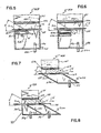
- a still further embodiment 410 is shown in Figure 5, and comprises a forming wire 412 movable in the direction A beneath the opening 411e of a distributor 411 provided with side plates 420.
- a suction box 415 is disposed beneath wire 412, in registry with distributor 411.
- the suction box 415 includes an endless belt 415c movable in the direction of arrow 8 over sprocketed rollers R and R', and the belt being disposed upstream of the direction of wire movement A while extending transversely of that direction of movement.
- Outlet port P-4 in the region downstream of belt 415c leads to inlet 416a of a suction pump in order to achieve non-uniform flow, at a predetermined desired acute angle H to the horizontal, is achieved through the blanking action of belt 415c.
- a rotatable brush 418 engages the lower run of belt 415c continuously to dislodge any dust or fibers passing through forming wire 412 and landing on the belt.
- a line again touching or passing through the upstream edge of distributor opening 411a and tangential to the downstream end of the belt defines angle Hwith the horizontal.
- the embodiment 510 shown in Figure 6 is similar to the Figure 5 embodiment in having side plates 520, and a forming wire 512 movable in the direction indicated by arrow A beneath opening 511a of a fiber distributor 511.
- a suction box 515 is disposed beneath the forming wire, in registry with distributor 511.
- the suction box 515 includes an outlet port P-6 adjacent the downstream side of suction box 515 and leading to inlet 516a of a suction pump in order to achieve flow through forming wire 512, at a predetermined acute angle H to the horizontal.
- a belt 515a is movable over sprocketed rollers R" transversely of the forming wire, and enhances deflection of fiber and airflow between the distributor 511 and the forming wire 512.
- a rotatable brush 515c is operative to clean the lower run of the belt 515a, advantageously disposing of the accumulation of dust and fibers thereon that normally results from sifting through the forming wire.
- the embodiment 610 seen in Figure 7 includes a distributor 611 with side plates and having its bottom opening 611a disposed above a forming wire 612 movable in the direction of arrow A.
- a suction box 615 is disposed beneath the forming wire so that its upper opening, which is slightly larger than the opening 611 a has its upstream or leading edge aligned with the corresponding odge of opening 611a; its downstream or trailing edge is disposed slightly downstream of opening 611a.
- a sealing roll 618 is positioned for rotation on an axis extending transversely of the forming wire, so that its upper left quadrant is close to the edge of opening 611a and its lowermost surface is in substantial line contact with a web in use formed on wire 612.
- the box 615 is of generally parallelogram shape viewed from the side and its upstream and downstream walls 615d and 615e, both slope downwardly and in the downstream direction at an angle of about 30 degrees to the horizontal.
- Outlet port P-7 is disposed in a downstream corner of the suction box.
- the construction and arrangement of this embodiment is such that air and fibers will impinge onto forming wire 612 at an acute angle H of about 30 degrees.
- the embodiment shown in Figure 8 comprises apparatus 710 similar to that shown in Figure 7, including the construction of distributor 711 and its opening 711a, forming wire 712 and its direction of travel A, side walls 720, and the provision of a sealing roll 718.
- Suction box 715 is substantially of trapezoidal shape and has a trailing, sloping wall 715e disposed with its upper edge slightly downstream of sealing roll 718.
- the suction box 715 also has an upstream, sloping wall 715d with its upper edge spaced slightly downstream from the leading edge of opening 711a, this wall constituting a partition within the box 715.
- the suction box 715 also includes an upstream extension defined by a vertical wall 715f in combination with wall 715d and an extension parallel to 715g of the bottom wall of the suction box.
- a cleanout port C-8 communicates with the suction box extension, which is in fact a dead space, and is used continuously or periodically to remove dust and fibers from this space.
- Outlet port P-8 is disposed in a downstream corner of suction box 715, and is cooperative with the other described structure to induce impingement of fibers at an acute angle H of from 21 degrees to 30 degrees onto forming wire 712.
- sealing means may be provided, such as those in Figures 1, 2, 7 and 8. Choice of the specific design is determined in each case to best cooperate with the remainder of the system.
- the sealing means in the arrangements illustrated in Figures 1 and 2 comprise the vane 17 or 117 located at the downstream side of the distributor 11,' 111.
Description
- This invention relates to improvements in apparatus and methods for the manufacture of fibrous webs, such as paper and the like. More particularly, but not exclusively, the invention is directed to improvements in the manufacture of tissue by the air-laying principle.
- In the manufacture of fibrous webs such as paper by the air-laying principle, care must be taken to ensure uniformity of distribution of fibers on a forming wire. Air laid fibrous webs have an undesirable tendency to form ripples that extend transversely of the forming wire whereby the web is weakened in the machine direction. These ripples form when attempts are made to operate at economical, high forming wire velocities in excess of a range from about 500 feet per minute (2.54 meters per second) to about 550 feet per minute (2.79 m/sec) and at economical air velocities in a range of from about 250 to about 300 feet per minute (1.27 to 1.52 m/sec) through the forming wire. The ripples do not tend to form at lesser forming wire velocities.
- U.S. Patent No. 4,004,323 discloses, in Figure 2, a formation duct disposed at an angle of incidence to a linear foraminous forming surface, the angle being in a range of from about 10 degrees to about 30 degrees, most preferably about 20 degrees. The patent further discloses that front and rear inner surfaces may be divergent at an angle of about 1 1/2 degrees, but preferably tQpt they be parallel; and that the forming surface speed may be in excess of 200 feet per minute (1.01 m/sec) or even more than 400 feet per minute (2.03 m/s). The velocity of air through the forming surface, the relative velocity of the fibers with respect to the forming surface in the direction of movement of the latter, and their practical importance in successful air laying are ignored.
- U.S. Patent No. 4,035,870 discloses a fiber conduit and a forming bell coaxially aligned along an axis disposed at an acute angle to the forming surface of a wire so that fibers are deposited on surface in a direction having a vector component coinciding with the direction of movement of
surface 16. - U.S. Patent No. 3,748,693 discloses vanes in a suction box having upstream and downstream air outlets. The vanes extend transversely of the direction of movement of a forming wire and are selectively adjustable to differentially restrict air flow through the wire so as to vary web thickness.
- By this invention we have sought to provide an improved method and apparatus for the manufacture of airlaid fiber webs, wherein the webs produced are substantially devoid of ripples. Improved means for uniformly distributing fibrous material onto a forming wire of apparatus for the manufacture of fibrous webs is disclosed hereinafter.
- The invention provides a method for forming dry fibers into a fibrous web substantially devoid of transverse ripples, comprising directing fibers in an inclined stream onto a planar section of a moving forming wire, characterised by moving the wire at a velocity in excess of 500 feet per minute (2.54 m/sec), maintaining the angle of impingement of the said stream on the planar section in a range from 21 to 30 degrees, and maintaining a pressure drop through the said planar section by causing air to flow therethrough at a velocity normal to the planar section in excess of 250 feet per minute (1.27 m/sec).
- For performing this method, the invention provides apparatus comprising a dry fibers distributor means a forming wire having a planar section disposed beneath the distributor means and linearly movable at a velocity in excess of about 500 feet per minute (2.54 m/sec), and a suction box disposed beneath the said planar section to draw air through the forming wire with a velocity component normal to the said planar section in excess of about 250 feet per minute (1.27 m/sec), the apparatus further including an array of parallel, mutually equally spaced vanes or baffles extending transversely of the said planar section, the vanes being located between the distributor means and the planar section and each being disposed obliquely to the planar section to cooperate with the suction box in directing the flow of fibers from the distributor means in the direction of movement of the forming wire at an acute angle in the range of 21 to 30 degrees to the said planar section. By way of example each vane comprises a segment of a hollow circular cylinder so positioned that a tangent to its upper edge is substantially parallel to the flow of air and fibers from the distributor means and a tangent to its lower edge is substantially parallel to the planar section. The alternative baffle is a plate which extends across a bottom opening provided in the distributor means in a direction transverse to the direction of movement of the forming wire and each plate is planar and is inclined downwardly in the direction of the said movement at an angle in the range from 21 to 30 degrees to the forming wire.
- In another apparatus for performing the aforesaid method, the apparatus according to the invention comprises a dry fibers distributor means, a forming wire having a planar section disposed beneath the distributor means and linearly movable at a velocity in excess of about 500 feet per minute (2.54 m/sec), and a suction box disposed beneath the said planar section to draw air through the forming wire at a velocity normal to the said planar section in excess of about 250 feet per minute (1.27 m/sec), the apparatus further including baffle means operative to provide fibers leaving the distributor means with a velocity component in the direction of movement of the wire, such that the fibers impinge on the wire at angles in the range of 21 to 30 degrees, the baffle means extending transverse to the forming wire movement horizontally over the upstream region of an upper, horizontally extending opening provided in the suction box beneath the forming wire, the baffle means including a free edge portion facing in the said direction of movement, and an imaginary line extending between an upstream edge of said distributor means and the free edge portion of the baffle plate extending downwardly in a downstream direction at an angle in the range of 21 to 30 degrees to the forming wire.
- A further apparatus according to the invention for performing the-aforesaid method comprises a dry fibers distributor means, a forming wire having a planar section disposed beneath the distributor means and linearly movable at a velocity in excess of about 500 feet per minute (2.54 m/sec), and a suction box disposed beneath the said planar section to draw air through the forming wire at a velocity normal to the said planar section in excess of about 250 feet per minute (1.27 m/sec), the apparatus further including an internal baffle plate in the suction box spaced from an upstream wall thereof, and an outlet port located in a region of the suction box downstream of the baffle plate for connection to a suction producing means, an imaginary line touching an upper edge of the baffle plate and an upstream edge of a bottom discharge opening of the distributor means making an angle of 21 to 30 degrees with the forming wire, and the baffle plate in conjunction with the suction being operative to provide fibers leaving the distributor means with a velocity component in the direction of movement of the wire to cause the fibers to impinge on the wire at an angle of 21 to 30 degrees.
- A still further apparatus according to the invention for performing the aforesaid method comprises a dry fiber distributor means having a bottom, horizontally extending opening, a forming wire having a planar section disposed beneath the said opening and linearly movable at a velocity in excess of 500 feet per minute (2.54 m/sec), and a suction box beneath the said planar section for drawing air through the said forming wire with a velocity component normal to the forming wire in excess of 250 feet per minute (1.27 m/sec), wherein the suction box is defined in part by parallel upstream and downstream walls that extend transversely of the direction of movement of the forming wire and are inclined downwardly in the said direction of movement at an angle in a range of 21 to 30 degrees to the horizontal, an upper edge of the downstream wall being spaced downstream of the distributor bottom opening and thereby providing a gap extending transversely of the direction of forming wire movement, an outlet port being disposed in a lower region of the suction box adjacent a lower edge of the downstream wall, and a sealing roll being provided extending transversely of the forming wire movement and partially covering the said gap, suction generated in the suction box being operative to provide fibers leaving the distributor means with a velocity component in the direction of movement of said forming wire such that the fibers impinge on the wire at angles in the range of 21 to 30 degrees.
- The invention will now be described in more detail, by way of example, with reference to the drawings, in which:
- Figure 1 is a diagrammatic elevational showing, with parts fragmented and parts in section, of fibrous web forming apparatus embodying the invention and useful in carrying out the method according to the invention; and
- Figures 2 to 8 are showings similar to Figure 1, and illustrating modified embodiments of the apparatus.
- Figure 1 shows an
apparatus 10 for forming a web of fibrous material, the apparatus comprising a set of dry fiber distributors 11 each including an impeller one of which is seen at 19. The impellers 19 are positioned above a horizontally-extending planar section of a formingwire 12 that is supported for movement on suitably mountedrollers 13 and 14 rotatable for movement of the upper flight of the forming wire in the direction of arrow A. The formingwire 12 in use travels at a predetermined velocity V,.Suction boxes 15 are disposed beneath formingwire 12, and each is offset at its right-hand, trailing edge in the downstream direction of movement of the wire (i.e., the "machine direction") with respect to the corresponding edge of the distributor 11. A pair of parallel deckles or side plates are provided along the sides of formingwire 12 at each distributor 11, only oneplate 20 of each pair being shown. Ablower 16 has its inlet 16a connected tosuction boxes 15 and its discharge 16b exits to atmosphere. Blower 16 is operative to create an air flow downwardly through the horizontal, upper flight section of the formingwire 12, the air flow being normal thereto, and at a velocity V2, which is about 250 feet per minute or preferably in excess of 250 feet per minute (1.27 m/sec). - An array of
arcuate vanes 17 extends across the bottom opening 11a of each of the distributors 11 betweenplates 20.Vanes 17 of each array are parallel, are mutually equally spaced and extend transversely of the direction of movement A of the formingwire 12. Eachvane 17 is a 90° segment of a hollow right circular cylinder, and is so positioned that the tangent to the upper edge is substantially perpendicular to the plane of opening 11a, i.e. substantially parallel to the flow of air and fibers from the distributor, and the tangent to the lower edge is substantially parallel to the direction of movement of the forming wire, and spaced preferably about 1/4 inch (6.3 mm) above the latter. The vanes are spaced one from the other so that the tangent T to the upper edge of one vane intersects the lower edge region of the next upstream vane, i.e. the next vane to the left as viewed in Fig. 1. - In accordance with the invention, the above-described trailing edge offset portion of
suction boxes 15, in combination with the shape and disposition ofvanes 17, is such as to impart a horizontal velocity componet V3 to the air, and to the air-entrained fibers flowing between the bottom openings 11a of distributors 11 and the surface of formingwire 12 via the spaces between thevanes 17. Ambient air drawn in at S enhances the horizontal component V3, while ambient air drawn in at S' aids in holding the web on the forming wire. This will be the case for the several embodiments where indicated. The horizontal velocity component V3 is less than the velocity V, of the forming wire, the latter being preferably in excess of about 500 feet per minute (2.54 m/sec). The amount of offset is such as to create an air and dry-fiber flow (from openings 11 a to the forming wire 12) which extends downwardly and in the direction of travel of the forming-wire at an angle H in a range of from 21 degrees to 30 degrees measured from the horizontally extending upper flight of the forming wire. Such an acute angle of fiber impingement on thewire 12 is based on the finding that successful web formation, free of ripples extending transversely of the forming wire (i.e.,across its width and across the machine direction) is achieved if the ratio of the total magnitude of the tangential velocity relative to the forming wire 12 (i.e. V,-V3) to that of the through air velocity normal to the forming wire (i.e. V2) induced by the suction box does not exceed about 2.5:1, wherein 2.5 is the cotangent of acute angle H and is approximately equal to 22 degrees. The web (not shown) formed on thewire 12 is removed from thewire 12 by suitable transfer apparatus of known construction (not shown), prior to movement of the wire overpulley 14. - In the embodiment shown in Figure 2,
apparatus 110 includes distributors 111 andside plates 112, only one of which is shown, beneath which there is a planar section of a formingwire 112 movable in the direction A at a predetermined velocity V,.Suction box 115 is disposed directly belowwire 112, and again is in registry with distributor 111 at its upstream end, but is offset at its right-hand, downstream end or trailing edge. The desired advantageous angular flow of fibers from opening 111a ontowire 112 is achieved by an array of parallel, mutually equally spaced flat vanes or baffle plates 117 extending across the opening 111a in a direction transverse to the direction of wire travel A and at an acute angle H to the horizontally extending forming wire, which angle is in the range of from 21 degrees to 30 degrees. Vanes 117 preferably are disposed so that their upper ends are vertically aligned with a flat portion of an adjacent upstream vane. This disposition and angular relationship, in combination with the velocity V2 of air normal to the formingwire 112, imparts the desired horizontal velocity component V3 to the fibers as described above. - The
embodiment 210 shown in Figure 3 includes a distributor 211 having an outlet opening 211a disposed in registry with thesuction box 215. Formingwire 212 is movable in the direction A, as in the above-described embodiments, andside plates 220 extend between the distributor and the forming wire. This embodiment is characterized by abaffle plate 215a extending horizontally from the left-hand or leading edge ofsuction box 215 and over a portion of the upper horizontal suction box opening 215b located beneath the forming wire. Baffleplate 215a extends transversely of the direction of move- mentA of thewire 212, and is so dimensioned in direction A that a line intersecting the left edge E of opening 211a of distributor 211 and the free edge E' of thebaffle plate 215a is at an acute angle H in order to achieve the desired angular air flow. The desired inclined air flow is further encouraged by the disposition of air outlet port P-2 of thesuction box 215 in a downstream region thereof. - Still another
embodiment 310 shown in Figure 4 includes a distributor 311 andside plates 320, as described above, and a formingwire 312 movable thereunder in the direction A. Asuction box 315 is disposed beneafh the forming wire, in substantial registry with the distributor. A vertical partition 315a extends transversely across the suction box beneath the formingwire 312, and is located toward the upstream side of the suction box with respect to the forming-wire movement. The upper edge F' of vertical baffle plate 315a is so positioned that a line touching it and the leading edge of the distributor opening is at an acute angle H of about 30 degrees to the horizontal. Outlet port P-3 is disposed in the right-hand, downstream region ofsuction box 315, so that flow of air through the outlet port to the inlet of the suction pump (not shown) further ensures achievement of the above described desired inclined flow of air and fiber. A cleanout port C-3 is provided to facilitate removal of any fibers or dust falling into the dead-zone between baffle plate 315a and the upstream wall of thesuction box 315. - A still further embodiment 410 is shown in Figure 5, and comprises a forming
wire 412 movable in the direction A beneath the opening 411e of a distributor 411 provided withside plates 420. Asuction box 415 is disposed beneathwire 412, in registry with distributor 411. Thesuction box 415 includes an endless belt 415c movable in the direction ofarrow 8 over sprocketed rollers R and R', and the belt being disposed upstream of the direction of wire movement A while extending transversely of that direction of movement. Outlet port P-4 in the region downstream of belt 415c leads toinlet 416a of a suction pump in order to achieve non-uniform flow, at a predetermined desired acute angle H to the horizontal, is achieved through the blanking action of belt 415c. A rotatable brush 418 engages the lower run of belt 415c continuously to dislodge any dust or fibers passing through formingwire 412 and landing on the belt. A line again touching or passing through the upstream edge of distributor opening 411a and tangential to the downstream end of the belt defines angle Hwith the horizontal. - The embodiment 510 shown in Figure 6 is similar to the Figure 5 embodiment in having
side plates 520, and a formingwire 512 movable in the direction indicated by arrow A beneath opening 511a of a fiber distributor 511. Asuction box 515 is disposed beneath the forming wire, in registry with distributor 511. Thesuction box 515 includes an outlet port P-6 adjacent the downstream side ofsuction box 515 and leading to inlet 516a of a suction pump in order to achieve flow through formingwire 512, at a predetermined acute angle H to the horizontal. Abelt 515a is movable over sprocketed rollers R" transversely of the forming wire, and enhances deflection of fiber and airflow between the distributor 511 and the formingwire 512. Arotatable brush 515c is operative to clean the lower run of thebelt 515a, advantageously disposing of the accumulation of dust and fibers thereon that normally results from sifting through the forming wire. - The
embodiment 610 seen in Figure 7 includes a distributor 611 with side plates and having its bottom opening 611a disposed above a formingwire 612 movable in the direction of arrow A. A suction box 615 is disposed beneath the forming wire so that its upper opening, which is slightly larger than the opening 611 a has its upstream or leading edge aligned with the corresponding odge of opening 611a; its downstream or trailing edge is disposed slightly downstream of opening 611a. A sealingroll 618 is positioned for rotation on an axis extending transversely of the forming wire, so that its upper left quadrant is close to the edge of opening 611a and its lowermost surface is in substantial line contact with a web in use formed onwire 612. Further to the construction of the suction box 615, there is a space between the trailing edge of its opening and roll 618. The box 615 is of generally parallelogram shape viewed from the side and its upstream anddownstream walls 615d and 615e, both slope downwardly and in the downstream direction at an angle of about 30 degrees to the horizontal. Outlet port P-7 is disposed in a downstream corner of the suction box. The construction and arrangement of this embodiment is such that air and fibers will impinge onto formingwire 612 at an acute angle H of about 30 degrees. - The embodiment shown in Figure 8 comprises
apparatus 710 similar to that shown in Figure 7, including the construction of distributor 711 and its opening 711a, forming wire 712 and its direction of travel A,side walls 720, and the provision of a sealingroll 718.Suction box 715 is substantially of trapezoidal shape and has a trailing, slopingwall 715e disposed with its upper edge slightly downstream of sealingroll 718. Thesuction box 715 also has an upstream, slopingwall 715d with its upper edge spaced slightly downstream from the leading edge of opening 711a, this wall constituting a partition within thebox 715. Thesuction box 715 also includes an upstream extension defined by a vertical wall 715f in combination withwall 715d and an extension parallel to 715g of the bottom wall of the suction box. A cleanout port C-8 communicates with the suction box extension, which is in fact a dead space, and is used continuously or periodically to remove dust and fibers from this space. Outlet port P-8 is disposed in a downstream corner ofsuction box 715, and is cooperative with the other described structure to induce impingement of fibers at an acute angle H of from 21 degrees to 30 degrees onto forming wire 712. - While no sealing means are shown on the downstream sides of the forming heads shown in Figures 3, 4, 5 and 6, one skilled in the art will appreciate that sealing means may be provided, such as those in Figures 1, 2, 7 and 8. Choice of the specific design is determined in each case to best cooperate with the remainder of the system. The sealing means in the arrangements illustrated in Figures 1 and 2 comprise the
vane 17 or 117 located at the downstream side of the distributor 11,' 111.
Claims (13)
Priority Applications (2)
| Application Number | Priority Date | Filing Date | Title |
|---|---|---|---|
| EP81301273A EP0060949B1 (en) | 1981-03-25 | 1981-03-25 | Apparatus for the manufacture of fibrous webs and method therefor |
| DE8181301273T DE3171295D1 (en) | 1981-03-25 | 1981-03-25 | Apparatus for the manufacture of fibrous webs and method therefor |
Applications Claiming Priority (1)
| Application Number | Priority Date | Filing Date | Title |
|---|---|---|---|
| EP81301273A EP0060949B1 (en) | 1981-03-25 | 1981-03-25 | Apparatus for the manufacture of fibrous webs and method therefor |
Publications (2)
| Publication Number | Publication Date |
|---|---|
| EP0060949A1 EP0060949A1 (en) | 1982-09-29 |
| EP0060949B1 true EP0060949B1 (en) | 1985-07-10 |
Family
ID=8188249
Family Applications (1)
| Application Number | Title | Priority Date | Filing Date |
|---|---|---|---|
| EP81301273A Expired EP0060949B1 (en) | 1981-03-25 | 1981-03-25 | Apparatus for the manufacture of fibrous webs and method therefor |
Country Status (2)
| Country | Link |
|---|---|
| EP (1) | EP0060949B1 (en) |
| DE (1) | DE3171295D1 (en) |
Families Citing this family (3)
| Publication number | Priority date | Publication date | Assignee | Title |
|---|---|---|---|---|
| US4765780A (en) * | 1986-05-28 | 1988-08-23 | The Procter & Gamble Company | Apparatus for and method of providing a multiplicity of streams of air-entrained fibers |
| SE503657C2 (en) * | 1994-11-07 | 1996-07-29 | Moelnlycke Ab | Device for forming fiber bodies on a continuous air-permeable path through aeration |
| RU2169223C2 (en) * | 1998-11-10 | 2001-06-20 | Общество с ограниченной ответственностью "Технобум" | Method of forming paper web from aerosuspension of fibrous material |
Citations (1)
| Publication number | Priority date | Publication date | Assignee | Title |
|---|---|---|---|---|
| US4004323A (en) * | 1975-04-10 | 1977-01-25 | Scott Paper Company | Method of forming a nonwoven fibrous web |
Family Cites Families (2)
| Publication number | Priority date | Publication date | Assignee | Title |
|---|---|---|---|---|
| US3755856A (en) * | 1971-04-23 | 1973-09-04 | Kimberly Clark Co | Method and apparatus for the formation of fiber fluff |
| FI760157A (en) * | 1976-01-23 | 1977-07-24 | Risto Tiitola |
-
1981
- 1981-03-25 EP EP81301273A patent/EP0060949B1/en not_active Expired
- 1981-03-25 DE DE8181301273T patent/DE3171295D1/en not_active Expired
Patent Citations (1)
| Publication number | Priority date | Publication date | Assignee | Title |
|---|---|---|---|---|
| US4004323A (en) * | 1975-04-10 | 1977-01-25 | Scott Paper Company | Method of forming a nonwoven fibrous web |
Also Published As
| Publication number | Publication date |
|---|---|
| DE3171295D1 (en) | 1985-08-14 |
| EP0060949A1 (en) | 1982-09-29 |
Similar Documents
| Publication | Publication Date | Title |
|---|---|---|
| EP0224892B1 (en) | Method and apparatus for producing a continuous web | |
| US4285647A (en) | Apparatus for the manufacture of fibrous webs | |
| US5443005A (en) | Dusting device | |
| US4144619A (en) | Dry-laying a web of particulate or fibrous material | |
| EP0006327A1 (en) | Apparatus for distributing fibres uniformly over a conveyor surface | |
| US4264290A (en) | Fiber velocity imparter device for dry-forming systems | |
| US4534086A (en) | Apparatus for making fibrous webs | |
| EP0060949B1 (en) | Apparatus for the manufacture of fibrous webs and method therefor | |
| GB2096877A (en) | Cigarette manufacture | |
| CA1042174A (en) | Fiber distribution and depositing apparatus | |
| US5810902A (en) | Method and apparatus for making air products | |
| JP4403632B2 (en) | Curtain coater air cut device | |
| US4180378A (en) | Apparatus for the deposition of dry fibers on a foraminous forming surface | |
| US4390336A (en) | Apparatus for air laid fiberglass mat | |
| EP0115272B1 (en) | Improved apparatus for forming dry laid webs | |
| US4627953A (en) | Method for forming dry laid webs | |
| US3801243A (en) | Apparatus for producing a mat | |
| US4319870A (en) | Apparatus for the manufacture of fibrous webs | |
| US3882818A (en) | Powder collector construction | |
| GB2111818A (en) | Distributor for a rod making machine for the production of smokers' articles | |
| FI82902C (en) | KRAEPPSCHABER. | |
| US4972551A (en) | Apparatus for making a non-woven fabric | |
| NO814393L (en) | METHOD AND APPARATUS FOR FIBER MATERIAL COLLECTION | |
| DK155441B (en) | Apparatus and process for producing fibre webs | |
| US5515873A (en) | Cigarette making machine |
Legal Events
| Date | Code | Title | Description |
|---|---|---|---|
| PUAI | Public reference made under article 153(3) epc to a published international application that has entered the european phase |
Free format text: ORIGINAL CODE: 0009012 |
|
| AK | Designated contracting states |
Designated state(s): DE FR SE |
|
| RAP1 | Party data changed (applicant data changed or rights of an application transferred) |
Owner name: JAMES RIVER-DIXIE/NORTHERN INC. |
|
| 17P | Request for examination filed |
Effective date: 19830305 |
|
| GRAA | (expected) grant |
Free format text: ORIGINAL CODE: 0009210 |
|
| RAP1 | Party data changed (applicant data changed or rights of an application transferred) |
Owner name: JAMES RIVER-NORWALK, INC. |
|
| AK | Designated contracting states |
Designated state(s): DE FR SE |
|
| REF | Corresponds to: |
Ref document number: 3171295 Country of ref document: DE Date of ref document: 19850814 |
|
| ET | Fr: translation filed | ||
| PLBE | No opposition filed within time limit |
Free format text: ORIGINAL CODE: 0009261 |
|
| STAA | Information on the status of an ep patent application or granted ep patent |
Free format text: STATUS: NO OPPOSITION FILED WITHIN TIME LIMIT |
|
| 26N | No opposition filed | ||
| PGFP | Annual fee paid to national office [announced via postgrant information from national office to epo] |
Ref country code: FR Payment date: 19910211 Year of fee payment: 11 |
|
| PGFP | Annual fee paid to national office [announced via postgrant information from national office to epo] |
Ref country code: SE Payment date: 19910218 Year of fee payment: 11 |
|
| PGFP | Annual fee paid to national office [announced via postgrant information from national office to epo] |
Ref country code: DE Payment date: 19910228 Year of fee payment: 11 |
|
| PG25 | Lapsed in a contracting state [announced via postgrant information from national office to epo] |
Ref country code: SE Effective date: 19920326 |
|
| PG25 | Lapsed in a contracting state [announced via postgrant information from national office to epo] |
Ref country code: FR Effective date: 19921130 |
|
| PG25 | Lapsed in a contracting state [announced via postgrant information from national office to epo] |
Ref country code: DE Effective date: 19921201 |
|
| REG | Reference to a national code |
Ref country code: FR Ref legal event code: ST |
|
| EUG | Se: european patent has lapsed |
Ref document number: 81301273.9 Effective date: 19921005 |