EP0060735B1 - Befestigungsvorrichtung des Endstücks einer Führungshülle eines verschiebbaren Bedienungskabels - Google Patents
Befestigungsvorrichtung des Endstücks einer Führungshülle eines verschiebbaren Bedienungskabels Download PDFInfo
- Publication number
- EP0060735B1 EP0060735B1 EP82400189A EP82400189A EP0060735B1 EP 0060735 B1 EP0060735 B1 EP 0060735B1 EP 82400189 A EP82400189 A EP 82400189A EP 82400189 A EP82400189 A EP 82400189A EP 0060735 B1 EP0060735 B1 EP 0060735B1
- Authority
- EP
- European Patent Office
- Prior art keywords
- socket
- sleeve
- cable
- extremity
- abutment
- Prior art date
- Legal status (The legal status is an assumption and is not a legal conclusion. Google has not performed a legal analysis and makes no representation as to the accuracy of the status listed.)
- Expired
Links
- 238000004873 anchoring Methods 0.000 title claims 2
- 230000002093 peripheral effect Effects 0.000 claims description 15
- 230000003100 immobilizing effect Effects 0.000 claims description 4
- 238000006073 displacement reaction Methods 0.000 claims description 2
- 230000001105 regulatory effect Effects 0.000 claims 1
- 239000011324 bead Substances 0.000 description 7
- 238000009434 installation Methods 0.000 description 7
- 230000006835 compression Effects 0.000 description 3
- 238000007906 compression Methods 0.000 description 3
- 238000011065 in-situ storage Methods 0.000 description 2
- 210000002105 tongue Anatomy 0.000 description 2
- 230000006978 adaptation Effects 0.000 description 1
- 230000000903 blocking effect Effects 0.000 description 1
- 239000004568 cement Substances 0.000 description 1
- 238000004519 manufacturing process Methods 0.000 description 1
- 238000000926 separation method Methods 0.000 description 1
Images
Classifications
-
- F—MECHANICAL ENGINEERING; LIGHTING; HEATING; WEAPONS; BLASTING
- F16—ENGINEERING ELEMENTS AND UNITS; GENERAL MEASURES FOR PRODUCING AND MAINTAINING EFFECTIVE FUNCTIONING OF MACHINES OR INSTALLATIONS; THERMAL INSULATION IN GENERAL
- F16C—SHAFTS; FLEXIBLE SHAFTS; ELEMENTS OR CRANKSHAFT MECHANISMS; ROTARY BODIES OTHER THAN GEARING ELEMENTS; BEARINGS
- F16C1/00—Flexible shafts; Mechanical means for transmitting movement in a flexible sheathing
- F16C1/10—Means for transmitting linear movement in a flexible sheathing, e.g. "Bowden-mechanisms"
- F16C1/22—Adjusting; Compensating length
- F16C1/226—Adjusting; Compensating length by adjusting the effective length of the sheathing
-
- F—MECHANICAL ENGINEERING; LIGHTING; HEATING; WEAPONS; BLASTING
- F16—ENGINEERING ELEMENTS AND UNITS; GENERAL MEASURES FOR PRODUCING AND MAINTAINING EFFECTIVE FUNCTIONING OF MACHINES OR INSTALLATIONS; THERMAL INSULATION IN GENERAL
- F16C—SHAFTS; FLEXIBLE SHAFTS; ELEMENTS OR CRANKSHAFT MECHANISMS; ROTARY BODIES OTHER THAN GEARING ELEMENTS; BEARINGS
- F16C1/00—Flexible shafts; Mechanical means for transmitting movement in a flexible sheathing
- F16C1/26—Construction of guiding-sheathings or guiding-tubes
- F16C1/262—End fittings; Attachment thereof to the sheathing or tube
-
- Y—GENERAL TAGGING OF NEW TECHNOLOGICAL DEVELOPMENTS; GENERAL TAGGING OF CROSS-SECTIONAL TECHNOLOGIES SPANNING OVER SEVERAL SECTIONS OF THE IPC; TECHNICAL SUBJECTS COVERED BY FORMER USPC CROSS-REFERENCE ART COLLECTIONS [XRACs] AND DIGESTS
- Y10—TECHNICAL SUBJECTS COVERED BY FORMER USPC
- Y10T—TECHNICAL SUBJECTS COVERED BY FORMER US CLASSIFICATION
- Y10T74/00—Machine element or mechanism
- Y10T74/20—Control lever and linkage systems
- Y10T74/20396—Hand operated
- Y10T74/20402—Flexible transmitter [e.g., Bowden cable]
- Y10T74/20408—Constant tension sustaining
Definitions
- the present invention relates to a device for fixing to a wall the end of a sheath in which is slidably received a control cable, comprising a sheath end piece associated with said end and designed to be received in an opening in the wall, said sheath end being slidably received in an internal bore of the end piece, the latter being provided with locking means which can be actuated by hand during the installation of the cable and the sheath so that the end of the sheath remains immobilized in the end piece during the use of the cable.
- Such a device is described for example in document US-A-2730134.
- Such cables are generally used on motor vehicles to control the brakes or a friction clutch. This type of cable is also used for the control of gearboxes, and in the latter case the cables used are of the "push-pull" type.
- These cables are generally installed between two fixed walls of a vehicle and the two end caps. sheath ends are each designed to be received in an opening in the corresponding wall. When the vehicle manufacturing tolerances become too large, it is sometimes difficult, if not impossible, to lay the cable on the vehicle that is to say to insert the two sheath ends in their respective opening, the length of sheath initially planned may be too short or too long, thus preventing the correct installation of the cable on the vehicle.
- the invention provides a device for fixing on a wall the end of a control cable sheath, allowing automatic adjustment of the sheath length during installation in situ sheathed cable, then immobilize the sheath in the adapted configuration thus obtained.
- the fixing device comprises an adjustment spring bearing on the end piece and elastically urging said sheath end away from said wall when the cable is put in place.
- the blocking means consist of a wedging system disposed between the internal wall of the end piece, and the external peripheral surface of the end of the sheath.
- the wedging system is advantageously of the ball wedging type between a surface of frustoconical bearing and the external surface of the sheath end.
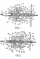
- FIG. 1 a fixing device designated by the general reference 10, on a fixed wall 12 of the end 14 of a cable sheath 16 in which a control cable 18 is received sliding.
- the fixing device 10 comprises a nozzle 11 received in a cover 20 of the wall in which it is force-fitted via its axial end 22 which is provided with beads 24 ensuring the fixing of the device 10 on the wall 12.
- the cable shown in Figure 1, consisting of the sheath 16 and the actual cable 18 is of the type generally used for the control of friction clutches, that is to say of the type which is used to carry out a force of traction on the cable.
- the sheath end 14 is constituted by a rigid metallic tubular piece fixed to the end 17 of the sheath 16.
- the sheath end 14 is slidably received in an internal bore 26 formed in the fixing device.
- the fixing device 10 is provided with locking means 30 making it possible to immobilize the end of the sheath 14 axially relative to the end piece 11.
- the locking device 30 is constituted by a system with wedging by balls arranged between the internal wall 32 of the end piece 11 and the external peripheral surface 15 of the sheath end 14.
- the ball-wedging system comprises a frustoconical bearing surface 34 formed on the internal wall 32 of the end piece 11.
- the frustoconical bearing surface 34 is formed on an attached ring 36 mounted in the internal bore constituting said internal wall 32 of the end piece 11.
- the system with wedging by balls comprises by elsewhere a ball cage 38 of generally tubular shape disposed between said frustoconical bearing 34 and the outer peripheral surface 15 of the end of the sheath 14, coaxial with the latter.
- the cage 38 is provided with balls 40 distributed circumferentially and arranged in radial bores 42 of the cage in which they are mounted to rotate.
- the sheath tip 11 comprises a first part 44 whose end 22 is received in the opening 20, and a second removable part 48.
- the first end part 44 is consisting of two elements 44 and 46 nested one inside the other during the assembly of said tip and thus made integral with one another.
- the end piece comprises a second removable part 48 on which the ball cage 38 is fixed.
- the ball cage 38 and the second end part 48 form only one piece mounted screwed by means of the thread 52 formed on the periphery of the second part 48 in a threaded internal bore 54 of the second element 46 of the first end part.
- the second removable part 48 is capable of moving axially, bringing with it the ball cage 38, relative to the first end part in which the frustoconical bearing 34 is formed.
- the device fixing 10 finally comprises an adjustment spring 56.
- the adjustment spring 56 is a helical compression spring mounted in an internal bore 60 of the sheath end 14 and which bears, on the one hand on a bearing surface 58 formed in the end piece 11 and on the other hand in the bottom 64 of the internal bore 60 of the sheath end 14.
- the adjustment spring 56 thus mounted resiliently biases the end of the sheath 14 and therefore the sheath 16 in distance from the wall 12, that is to say in the direction indicated by the arrow A in FIG. 1.
- the fixing device 10 is shown in FIG. 1 after the control cable has been fitted on the vehicle, that is to say when the locking means constituted by the wedging system 30 immobilize the end of the sheath 14 relative to to the end piece 11 and therefore relative to the wall 12.
- the installation of the fixing device and the cable on the vehicle is carried out as follows: after having unscrewed the second part of the end piece 48 relative to the element 46 of the first tip part until the sheath end 14 is free to slide relative to the tip 11, that is to say in an axial position in which the balls 40 do not are more in contact with the frustoconical bearing surface 34 and the outer peripheral surface 15 of the sheath end 14, the operator fits the end 22 of the nozzle 11 into the opening of the wall 20.
- the operator can then fit a sheath end of a conventional type provided at the other end of the sheath 16 (n shown) in an opening of another wall of the vehicle.
- the sheathed end 14 is free to slide axially in the internal bore 26 formed in the second part 48 of the end piece 11 and in the coaxial internal bore 66 formed in the first part end piece 44. Thanks to this sliding, the installation of the cable is easy, because a sheath of variable length is produced making it possible to adapt to all the variations in tolerances separating the two walls of the vehicle in which the ends are mounted sheath.
- This adaptation of the sheath length is facilitated by the adjustment spring 56 which urges the sheath 16 away from the wall 12 and therefore towards the second wall, not shown.
- FIG. 2 a second embodiment of a sheath fixing device on a wall.
- the cable used is of the push-pull type used for the control of gearboxes.
- the elements of Figure 2 identical or equivalent to the elements already shown in Figure 1 are designated by the same reference numbers increased by 100.
- the device 110 shown in Figure 2 comprises an end piece 111 consisting of a first end part 144 and a second end part 148.
- the first end part 144 is received telescopically in the second end part 148 by means of the external wall 170 which slides in the internal bore 172 of the second part d 'end piece 148.
- the fixing device shown being intended to allow the installation of a cable of the push-pull type, it is provided with a second wedging system 174, identical to the wedging system 130 but arranged symmetrically relative to a median plane of the device 110.
- the device 174 in fact comprises a ball cage 176 provided with balls 178 capable of cooperating with a frustoconical bearing surface 180 formed on an attached tubular part 136 on which is formed the frustoconical bearing surface 134 and with the outer peripheral wall 115 of the sheath end 114.
- the axial position of the second end portion 148 telescopically mounted cement on the first end portion 144 is determined by relative axial immobilization means constituted by two beads 182 and 184 formed at the outer peripheral surface 170 of the first end portion 144, and which are capable of cooperating with a external peripheral notch 186 formed in the second end part 148.
- the cooperation of the beads 182 and 184 with the external notch 186 constitutes a system for snapping the first end part 144 into the second end part 148 allowing to immobilize axially the relative position of these two elements.
- the different components of the fixing device 110 are shown in Figure 2 in the position they occupy when the cable is put in place on the vehicle, that is to say before the axial end of the sheath end by relative to the end piece 111.
- the systems with wedging by balls 130 and 174 are free, that is to say that the balls 138 and 182 are not wedged between their respective frustoconical bearing surfaces 134 and 180 and the outer peripheral surface 115 of the end of the sheath 114.
- the operator can carry out the positioning of the control cable on the vehicle in a manner identical to that which has been described for the first embodiment illustrated in Figure 1.
- the operator When the operator has installed the cable and the sheath length has been adjusted automatically under the action of the adjusting spring 156, the operator must then perform the bl ocage of the systems with wedging by balls 130 and 174. To do this, the operator biases the second end part 148 axially in the direction indicated by the arrow B in FIG. 2, against the stop defined by the cooperation between the bead 184 and the surface 186 formed at the lateral end of the second part 148, until the bead 84 comes to cooperate with the lateral end surface 190 of the external peripheral notch 186 in its place of the bead 182.
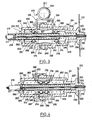
- FIGS. 3 and 4 show a third embodiment of a device for fixing one end of control cable sheath on a wall.
- the cable used is of the pull-push type like that shown in Figure 2.
- the elements of the fixing device shown in Figures 3 and 4, identical or equivalent to the device 110 of Figure 2, are designated by the same reference numerals increased by 100.
- the two ball cages 238 and 276 of the two ball jam systems 230 and 274 are mounted axially free relative to the body of the endpiece 211 which in this embodiment includes two elements forming a housing 300 and 302.
- the ball cages 238 and 276 are each provided with a wedging spring 306 and 308 respectively.
- the jamming spring 306 is a helical compression spring bearing on a bearing surface 310 formed in the element 302 of the end piece 11 and on a surface 240 formed on the ball cage 238.
- the jamming spring 306 thus disposed resiliently biases the ball cage 238 in the direction of the conical bearing surface 234 that is to say in the axial direction corresponding to the jamming of the balls 240 between the frustoconical bearing surface 234 and the outer peripheral wall 215 of the sheath end 214.
- the jamming spring 308 is a helical compression spring bearing on the surfaces 314 formed in the first element 300 of the housing of the endpiece 211, and the bearing surface 316 formed on the end of the ball cage 276.
- the fixing device comprises removable stop means 320, axially immobilizing the cages with balls 238 and 276 against the elastic forces exerted by the jamming springs 306 and 308, in a position, shown in Figure 3, in which the balls 240 and 278 are not wedged between the frustoconical bearing surfaces 234 and 280 and the external peripheral surface 215 of the end of the sheath 214, the latter being free to slide relative to the end piece 211 so as to allow the cable to be placed on the vehicle.
- the removable stop means 320 are, in the embodiment shown, constituted by a single element which combines two removable stop means 322 and 324 which each cooperate with the ball cages 238 and 276 respectively.
- the stop means 322 will be described by way of example.
- the removable stop means 320 is constituted by a pin, slidably mounted in a radial bore 326 formed in the end piece 211 and the end 327 of which cooperates with a stop surface 328 formed at the end of the cage 238.
- the removable stop means 322 and 324 are connected by a loop 330 integrally formed therewith which facilitates the removal of the removable stop means after the cable has been placed on the vehicle.
- the balls 240 and 278 are wedged between the frustoconical bearing surfaces 234 and 280 and the external peripheral surface 215 of the sheath end 214, and are biased in this position by the wedging springs 306 and 308.
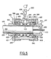
- FIG. 5 shows a fourth embodiment of a device for fixing an end of the control cable sheath to a wall.
- This fourth embodiment is very close to the device shown in Figures 3 and 4 and differs from it only in details of embodiments.
- the elements of the fastening device shown in Figure 5 identical or equivalent to the elements of the device shown in Figures 3 and 4 are designated by the same reference numerals increased by 200.
- the two ball cages 438 and 476 are each provided with a clamping spring 506 and 508 respectively which came integrally with each of the ball cages.
- the ball cages are made of plastic and the springs 506 and 508 are constituted by tongues 600 and 602 formed integrally with the cages 438 and 476.
- the tongues 600 and 602 extend from the lateral end walls 440 and 516 of cages 438 and 476 and bear by their free ends 601 and 603 on the bearing faces 510 and 514 formed in the end halves 502 and 500.
- Such an embodiment of the wedging springs 10 reduces the number of components of the device and thereby its cost price.
- the removable stop means 520 consist of the end 604 of a tool such as a screwdriver 606 which can be introduced into a radial bore 608 formed in the attached tubular part 436.
- a tool such as a screwdriver 606 which can be introduced into a radial bore 608 formed in the attached tubular part 436.
- the invention is not limited to the embodiments which have just been described and each of them can in particular be adapted to the two types of cable mentioned above, for example, the device shown in Figure 2 can be simplified to be mounted on a cable of the pull type only, eliminating the second system with wedging by balls 274 and immobilizing the position of the attached tubular element 136 on which the frustoconical bearing surface is formed, relative to the first part of tip 144.
Landscapes
- Engineering & Computer Science (AREA)
- General Engineering & Computer Science (AREA)
- Health & Medical Sciences (AREA)
- Oral & Maxillofacial Surgery (AREA)
- Mechanical Engineering (AREA)
- Flexible Shafts (AREA)
- Transmission Of Braking Force In Braking Systems (AREA)
Claims (11)
Applications Claiming Priority (2)
| Application Number | Priority Date | Filing Date | Title |
|---|---|---|---|
| FR8103947 | 1981-02-27 | ||
| FR8103947A FR2500896A1 (fr) | 1981-02-27 | 1981-02-27 | Dispositif de fixation sur une paroi de l'extremite d'une gaine dans laquelle est recu coulissant un cable de commande |
Publications (2)
| Publication Number | Publication Date |
|---|---|
| EP0060735A1 EP0060735A1 (de) | 1982-09-22 |
| EP0060735B1 true EP0060735B1 (de) | 1984-11-28 |
Family
ID=9255693
Family Applications (1)
| Application Number | Title | Priority Date | Filing Date |
|---|---|---|---|
| EP82400189A Expired EP0060735B1 (de) | 1981-02-27 | 1982-02-04 | Befestigungsvorrichtung des Endstücks einer Führungshülle eines verschiebbaren Bedienungskabels |
Country Status (9)
| Country | Link |
|---|---|
| US (1) | US4549709A (de) |
| EP (1) | EP0060735B1 (de) |
| JP (1) | JPS57161311A (de) |
| AR (1) | AR225717A1 (de) |
| AU (1) | AU549511B2 (de) |
| DE (1) | DE3261318D1 (de) |
| ES (1) | ES509600A0 (de) |
| FR (1) | FR2500896A1 (de) |
| PT (1) | PT74421B (de) |
Cited By (1)
| Publication number | Priority date | Publication date | Assignee | Title |
|---|---|---|---|---|
| WO2013121147A2 (fr) | 2012-02-15 | 2013-08-22 | Moving Magnet Technologies | Actionneur a entrainement direct compact generant une force constante |
Families Citing this family (9)
| Publication number | Priority date | Publication date | Assignee | Title |
|---|---|---|---|---|
| FR2521659B1 (fr) * | 1982-02-15 | 1985-06-21 | Dba | Dispositif de fixation sur une paroi d'une gaine flexible et procede de fixation d'une gaine au moyen d'un tel dispositif |
| FR2551149B1 (fr) * | 1983-08-25 | 1985-10-18 | Dba | Dispositif de commande mecanique a cable avec systeme de prereglage |
| GB2157789A (en) * | 1984-01-19 | 1985-10-30 | Bowden Controls Ltd | Self-adjusting clutch control mechanism |
| ES2004442A6 (es) * | 1987-07-02 | 1989-01-01 | Pujol & Tarago | Regulador automatico de la longitud de cables de mando |
| US4854186A (en) * | 1987-12-02 | 1989-08-08 | Kuster & Co. Gmbh | Apparatus for adjusting the length of a bowden cable |
| ES2024094A6 (es) * | 1990-03-22 | 1992-02-16 | Pujol & Tarago | Dispositivo de incremento de esfuerzo para cables de acelerador en vehiculos automoviles. |
| FR2710428B1 (fr) * | 1993-09-21 | 1995-12-15 | Blg Systemes | Dispositif pour la mise sous tension automatique d'un câble de commande. |
| US8037973B2 (en) * | 2008-06-10 | 2011-10-18 | Ruei-Hsing Lin | Fixing device for anti-slip cable lock |
| IT1396378B1 (it) * | 2009-10-29 | 2012-11-19 | Meccanica Finnord Spa | Dispositivo per la regolazione automatica della tensione applicata a un cavo di controllo. |
Family Cites Families (14)
| Publication number | Priority date | Publication date | Assignee | Title |
|---|---|---|---|---|
| US2417581A (en) * | 1942-12-31 | 1947-03-18 | Cons Vultee Aircraft Corp | Automatically compensating cable connection |
| US2597270A (en) * | 1949-08-02 | 1952-05-20 | Boeing Co | Cable tension thermal compensator |
| US2730134A (en) * | 1950-10-06 | 1956-01-10 | John F Morse | Casing for push-pull cable assembly |
| US2957354A (en) * | 1958-02-21 | 1960-10-25 | Avro Aircraft Ltd | Mechanical actuating device |
| GB1366325A (en) * | 1970-10-08 | 1974-09-11 | Teleflex Inc | Remote control assembly |
| US3744008A (en) * | 1971-11-23 | 1973-07-03 | Thomas & Betts Corp | Strain relief assembly |
| FR2278982A1 (fr) * | 1974-03-19 | 1976-02-13 | Huret Roger | Dispositif de rattrapage du jeu dans une transmission par cable |
| DE2532661C3 (de) * | 1975-07-22 | 1978-03-09 | Jean Walterscheid Gmbh, 5204 Lohmar | Teleskopwelle, insbesondere für Landmaschinen |
| US4068750A (en) * | 1976-12-22 | 1978-01-17 | Borg-Warner Corporation | Automatic adjuster for clutch linkages |
| US4141117A (en) * | 1977-06-09 | 1979-02-27 | Brammall, Inc. | Releasing tool for use with a releasable cone lock |
| JPS5447956A (en) * | 1977-09-24 | 1979-04-16 | Hideo Arakawa | Universal retainer and universal retaining device |
| FR2420164A1 (fr) * | 1978-03-17 | 1979-10-12 | Ferodo Sa | Dispositif compensateur pour tringlerie de transmission |
| US4297913A (en) * | 1979-03-29 | 1981-11-03 | Garbo Paul W | Remote control having push-pull blade with captive rolling elements |
| FR2470994A1 (fr) * | 1979-12-07 | 1981-06-12 | Dba | Commande mecanique par cable coulissant axialement dans une gaine flexible |
-
1981
- 1981-02-27 FR FR8103947A patent/FR2500896A1/fr active Granted
-
1982
- 1982-02-04 EP EP82400189A patent/EP0060735B1/de not_active Expired
- 1982-02-04 DE DE8282400189T patent/DE3261318D1/de not_active Expired
- 1982-02-12 PT PT74421A patent/PT74421B/pt unknown
- 1982-02-12 AR AR288421A patent/AR225717A1/es active
- 1982-02-15 ES ES509600A patent/ES509600A0/es active Granted
- 1982-02-15 JP JP57021334A patent/JPS57161311A/ja active Pending
- 1982-02-18 US US06/349,889 patent/US4549709A/en not_active Expired - Fee Related
- 1982-02-23 AU AU80716/82A patent/AU549511B2/en not_active Ceased
Cited By (1)
| Publication number | Priority date | Publication date | Assignee | Title |
|---|---|---|---|---|
| WO2013121147A2 (fr) | 2012-02-15 | 2013-08-22 | Moving Magnet Technologies | Actionneur a entrainement direct compact generant une force constante |
Also Published As
| Publication number | Publication date |
|---|---|
| US4549709A (en) | 1985-10-29 |
| DE3261318D1 (en) | 1985-01-10 |
| FR2500896B1 (de) | 1984-11-30 |
| AU8071682A (en) | 1982-09-02 |
| ES8302226A1 (es) | 1983-01-16 |
| JPS57161311A (en) | 1982-10-04 |
| PT74421A (en) | 1982-03-01 |
| EP0060735A1 (de) | 1982-09-22 |
| FR2500896A1 (fr) | 1982-09-03 |
| ES509600A0 (es) | 1983-01-16 |
| AU549511B2 (en) | 1986-01-30 |
| AR225717A1 (es) | 1982-04-15 |
| PT74421B (en) | 1983-09-27 |
Similar Documents
| Publication | Publication Date | Title |
|---|---|---|
| EP0196931B1 (de) | Kabelzug mit selbsttätiger Nachstellvorrichtung | |
| EP2047879B1 (de) | Sicherheitseinrichtung für eine Spritzvorrichtung | |
| EP0055649B1 (de) | Mechanische Betätigungsvorrichtung mit einem in einer biegsamen Hülle längsverschiebbaren Kabel | |
| EP0060735B1 (de) | Befestigungsvorrichtung des Endstücks einer Führungshülle eines verschiebbaren Bedienungskabels | |
| EP0036368B1 (de) | Scheibenbremse | |
| EP0250285B1 (de) | Bremsmotor mit einer rückstellbaren automatischen Nachstellvorrichtung | |
| FR2816029A1 (fr) | Dispositif de raccordement comportant des moyens de connexion instantanee d'une extremite de conduite a un organe et des moyens de protection de la connexion | |
| EP0086717B1 (de) | Befestigungsvorrichtung einer biegsamen Hülle an einer Platte | |
| EP0224393B1 (de) | Trennbarer Zusammenbau eines ein Entriegelungselement tragenden Kupplungsausrücklagers, insbesondere für Kraftfahrzeuge | |
| EP0223645B1 (de) | Trennbarer Zusammenbau eines Kupplungsausrücklagers, insbesondere für Kraftfahrzeuge | |
| EP0192081B1 (de) | Zugkraftbetätigtes Kupplungslager | |
| EP0486341B1 (de) | Mechanisch betätigbare Trommelbremse | |
| FR2701682A1 (fr) | Ensemble de colonne de direction escamotable en cas de choc. | |
| EP3885592B1 (de) | Blindmontageanordnung eines bremsseils an einem betätigungshebel einer kraftfahrzeug-trommelbremse und montageverfahren | |
| EP0791758A1 (de) | Bajonettschnellkupplung | |
| EP0345401A1 (de) | Vorrichtung zur lösbaren Befestigung von Schnurführungsösen an Fischerruten | |
| FR2595841A1 (fr) | Dispositif de commande mecanique a cable a reglage automatique | |
| EP0090731B1 (de) | Einstell- und Kontrollvorrichtung für ein Handbremsseil von Trommelbremsen und Trommelbremse mit solcher Vorrichtung | |
| EP3746682B1 (de) | Kabelende und vorrichtung zur einstellung eines steuerkabels bei einem getriebe | |
| FR2865014A1 (fr) | Embout de maintien d'un element allonge sur une paroi de support | |
| EP0327458A1 (de) | Handbremsbedienung, insbesondere für Kraftfahrzeug | |
| FR2725481A1 (fr) | Dispositif de reglage pour commande a cable | |
| FR2701079A1 (fr) | Dispositif de débrayage à encliqueter sur un embrayage de type tiré. | |
| FR2596211A1 (fr) | Connecteur electrique a verrouillage et a controles redondants de l'accouplement correct de ses deux elements constitutifs | |
| EP0421851A1 (de) | Zugkraftbetätigtes Kupplungslager |
Legal Events
| Date | Code | Title | Description |
|---|---|---|---|
| PUAI | Public reference made under article 153(3) epc to a published international application that has entered the european phase |
Free format text: ORIGINAL CODE: 0009012 |
|
| 17P | Request for examination filed |
Effective date: 19820216 |
|
| AK | Designated contracting states |
Designated state(s): DE FR GB IT |
|
| ITF | It: translation for a ep patent filed | ||
| GRAA | (expected) grant |
Free format text: ORIGINAL CODE: 0009210 |
|
| AK | Designated contracting states |
Designated state(s): DE FR GB IT |
|
| PGFP | Annual fee paid to national office [announced via postgrant information from national office to epo] |
Ref country code: DE Payment date: 19841224 Year of fee payment: 4 |
|
| REF | Corresponds to: |
Ref document number: 3261318 Country of ref document: DE Date of ref document: 19850110 |
|
| PLBE | No opposition filed within time limit |
Free format text: ORIGINAL CODE: 0009261 |
|
| STAA | Information on the status of an ep patent application or granted ep patent |
Free format text: STATUS: NO OPPOSITION FILED WITHIN TIME LIMIT |
|
| 26N | No opposition filed | ||
| ITPR | It: changes in ownership of a european patent |
Owner name: CESSIONE;SOCIETE DES CABLES DU MANS S.A. |
|
| REG | Reference to a national code |
Ref country code: GB Ref legal event code: 732 |
|
| PG25 | Lapsed in a contracting state [announced via postgrant information from national office to epo] |
Ref country code: DE Effective date: 19881101 |
|
| PGFP | Annual fee paid to national office [announced via postgrant information from national office to epo] |
Ref country code: FR Payment date: 19910226 Year of fee payment: 10 |
|
| ITTA | It: last paid annual fee | ||
| PGFP | Annual fee paid to national office [announced via postgrant information from national office to epo] |
Ref country code: GB Payment date: 19910528 Year of fee payment: 10 |
|
| PG25 | Lapsed in a contracting state [announced via postgrant information from national office to epo] |
Ref country code: GB Effective date: 19920204 |
|
| GBPC | Gb: european patent ceased through non-payment of renewal fee | ||
| PG25 | Lapsed in a contracting state [announced via postgrant information from national office to epo] |
Ref country code: FR Effective date: 19921030 |
|
| REG | Reference to a national code |
Ref country code: FR Ref legal event code: ST |