EP0060102A2 - Differentialgetriebe - Google Patents
Differentialgetriebe Download PDFInfo
- Publication number
- EP0060102A2 EP0060102A2 EP82301127A EP82301127A EP0060102A2 EP 0060102 A2 EP0060102 A2 EP 0060102A2 EP 82301127 A EP82301127 A EP 82301127A EP 82301127 A EP82301127 A EP 82301127A EP 0060102 A2 EP0060102 A2 EP 0060102A2
- Authority
- EP
- European Patent Office
- Prior art keywords
- gear
- wheels
- planet
- planet wheels
- wheel
- Prior art date
- Legal status (The legal status is an assumption and is not a legal conclusion. Google has not performed a legal analysis and makes no representation as to the accuracy of the status listed.)
- Withdrawn
Links
Images
Classifications
-
- F—MECHANICAL ENGINEERING; LIGHTING; HEATING; WEAPONS; BLASTING
- F16—ENGINEERING ELEMENTS AND UNITS; GENERAL MEASURES FOR PRODUCING AND MAINTAINING EFFECTIVE FUNCTIONING OF MACHINES OR INSTALLATIONS; THERMAL INSULATION IN GENERAL
- F16H—GEARING
- F16H48/00—Differential gearings
- F16H48/20—Arrangements for suppressing or influencing the differential action, e.g. locking devices
- F16H48/27—Arrangements for suppressing or influencing the differential action, e.g. locking devices using internally-actuatable fluid pressure, e.g. internal pump types
-
- F—MECHANICAL ENGINEERING; LIGHTING; HEATING; WEAPONS; BLASTING
- F16—ENGINEERING ELEMENTS AND UNITS; GENERAL MEASURES FOR PRODUCING AND MAINTAINING EFFECTIVE FUNCTIONING OF MACHINES OR INSTALLATIONS; THERMAL INSULATION IN GENERAL
- F16H—GEARING
- F16H48/00—Differential gearings
- F16H48/06—Differential gearings with gears having orbital motion
- F16H48/10—Differential gearings with gears having orbital motion with orbital spur gears
Definitions
- This invention relates to differential gears and is particularly, but not exclusively, applicable to differential gears for mechanically propelled vehicles.
- a differential gear is provided between the vehicle engine and the driven wheels. If there is only a single pair of driven wheels, the differential gear is provided to enable the driven wheels to rotate at different speeds when the vehicle is travelling along a curved path. When there are two or more pairs of driven wheels, it is also normal practice to provide a differential gear between each driven pair so that these pairs can rotate at different speeds.
- the invention consists in a differential gear comprising: an input shaft driving a planet wheel carrier; a first output shaft driven by a first gear wheel meshing with the planet wheels of said carrier; a second output shaft driven by a second gear wheel meshing with said planet wheels; and means for introducing fluid under pressure between the meshing teeth of said planet wheels and at least one of said gear wheels in order to restrict relative rotation between said planet wheels and said gear wheels.
- each of the planet wheels in combination with one or both of the gear wheels, to act like a gear pump.
- This pumping . action imposes a load on the planet wheel which tends to restrict relative rotation between that planet wheel and the gear wheel with which it is in mesh.
- references herein to the introduction of fluid under pressure includes pressure produced as the result of gravity.
- a reservoir of fluid may be provided at a height above the height of the differential gear, and this reservoir may be connected to the planet wheels or said at least one of said gear wheels by suitable ducting.
- the gears run in relatively wide open spaces and are lubricated by splash.
- the gears run in relatively confined spaces and thus trap the oil to impose a load on the planet wheels as hereinbefore referred to.
- the invention may be applied to a conventional differential gear of the type normally used in a vehicle with a single driven axle.
- the propeller shaft of the vehicle normally drives a bevel pinion in mesh with a crown wheel.
- the crown wheel carries a cage having an axle perpendicular to its own axis of rotation.
- This axle carries a pair of planet pinions which are both in mesh with a pair of sun gears carried on coaxial shafts.
- One of the coaxial shafts drives the off-side driven wheel of the vehicle, while the other shaft drives the near-side driven wheel.
- the planet wheel carrier is constituted by the cage
- the planet wheels are constituted by the two planet pinions
- the first and second gear wheels are constituted respectively by the two sun gears.
- the fluid which is preferably oil
- the fluid may be introduced, for example, into the two coaxial shafts.
- An axial passage is provided in each of these shafts which communicates with a plurality of radial passages in the respective sun gear.
- These radial passages open between adjacent teeth of the sun gear so that oil is pumped to the interface between the.. teeth of the sun gear and the planet pinions.
- the pumping action will impose a load on relative rotation between each sun gear and the differential planet pinions which will allow differential rotation between the two coaxial shafts up to a predetermined speed, but will inhibit relative rotation between the two coaxial shafts if this rotation exceeds the predetermined limit.
- This limit is set by the rate at which the oil can be dissipated from the interfaces between the meshing teeth, and can be determined by the tolerance allowed in the design of the teeth.
- This type of differential is used particularly in vehicles having a plurality of driven axles being located between the propeller shafts driving the respective axles.
- a proportioning differential comprises a planet wheel carrier on which is mounted a plurality of planet wheels rotatable about axes parallel to the axis of rotation of the carrier. These planet wheels are in mesh with a sun wheel which is fixed to the first output shaft of the differential. The planet wheels are also in mesh with internal teeth of an annular gear which is fixed to the second output shaft. It is to be understood that, in a differential of -this kind, the torque supplied by the input shaft is divided between the two output shafts in proportion to the gear-ratio between the sun wheel and the annulus.
- oil under pressure is preferably provided to an axial passage in the shaft carrying the sun wheel.
- This axial passage communicates with a plurality of radial passages which open between adjacent teeth of the sun wheel.
- gear wheels are rotatably mounted on the planet wheel carrier.
- These gear wheels are of a slightly smaller diameter than the planet wheels, and each is in mesh with a respective one of the planet wheels. However, they are so located that they are not in mesh with either the sun wheel or the annulus.
- each planet wheel and its associated gear wheel can be designed as a true gear- pump so that the amount of load applied by the pumping action on the planet wheels can be accurately determined and readily altered if desired by changing the gear wheels.
- the main components of the differential can always be standard, and the differential can be adjusted for different conditions by supplying interchangeable gear wheels.
- restriction on relative rotation between the two output 'shafts can be adjusted by providing a variable-delivery oil pump for supplying the oil to the interfaces.
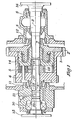
- the differential gear illustrated includes a planet wheel carrier 1 provided with gear teeth 2 by means of which it can be rotated about an axis 3.
- the carrier 1 is provided with three shafts such as that illustrated at 4, on each of which is rotatably mounted a planet wheel 5.
- the differential gear illustrated. includes two output shafts 6 and 7 which are also rotable about the axis 3. As shown, the shaft 7 is mounted for rotation in tapered roller bearings 8 and 9, and the output shaft 6 is rotatable in a bearing 10.
- the planet wheel carrier 1 is rotatably mounted on the shafts 6 and 7 by means of respective tapered roller bearings 11 and 12.
- the differential gear illustrated is intended for connection between the propeller shafts of two pairs of driven axles of a vehicle.
- the shaft 6 is connected to the propeller shaft for the forward axle by means of a coupling plate 15, and the shaft 7 is connected to the rear propeller shaft by means of a plate 16.
- the propeller shaft from the vehicle engine carries a gear wheel which meshes with the teeth 2 on the planet wheel carrier 1.
- an axial drilling 17 is provided in the shaft 6, and this axial drilling communicates at one end with a plurality of radial drillings 18, and, at the other end, with a radial drilling 19.
- the radial drilling 19 communicates with an annular chamber 20 to which oil is supplied under pressure through a channel 21.
- the radial drillings 18 pass through the sun wheel 13 and open between adjacent teeth of the sun wheel.
- oil is supplied under pressure from the channel 21 to the interfaces between the teeth of the sun wheel 18 and the teeth of the respective planet wheels 5.
- the mating teeth act in the manner of a gear pump and relative rotation between the planet wheels and the sun wheel is limited by the speed at which the oil can be dissipated from these interfaces.
- relative rotation between the shafts 6 and 7 is limited and, if the wheels of one axle commence to slip, drive will still be applied to the other axle because of the inhibiting action of the oil between the teeth of the planet wheels and the sun wheel.
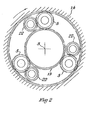
- additional gear wheels 22 are provided in mesh with the planet wheels 5.
- These gear wheels 22 are rotatably mounted in the planet wheel carrier 1 and are dimensioned so that they are not in mesh with either the sun gear 3 or the annulus 14.
- each one of these gear wheels, in combination with the respective planet wheel 5, ccn-. stitutes a true gear pump.
- the tolerances between the teeth of these gear wheels and the respective planet wheels can be chosen to provide the required degree of restriction on rotation of the planet wheels.
Landscapes
- Engineering & Computer Science (AREA)
- General Engineering & Computer Science (AREA)
- Mechanical Engineering (AREA)
- Physics & Mathematics (AREA)
- Fluid Mechanics (AREA)
- Retarders (AREA)
Applications Claiming Priority (2)
| Application Number | Priority Date | Filing Date | Title |
|---|---|---|---|
| GB8107473A GB2094422A (en) | 1981-03-10 | 1981-03-10 | Improvements in or relating to differential gears |
| GB8107473 | 1981-03-10 |
Publications (2)
| Publication Number | Publication Date |
|---|---|
| EP0060102A2 true EP0060102A2 (de) | 1982-09-15 |
| EP0060102A3 EP0060102A3 (de) | 1983-06-22 |
Family
ID=10520277
Family Applications (1)
| Application Number | Title | Priority Date | Filing Date |
|---|---|---|---|
| EP82301127A Withdrawn EP0060102A3 (de) | 1981-03-10 | 1982-03-05 | Differentialgetriebe |
Country Status (3)
| Country | Link |
|---|---|
| EP (1) | EP0060102A3 (de) |
| GB (1) | GB2094422A (de) |
| ZA (1) | ZA821501B (de) |
Families Citing this family (1)
| Publication number | Priority date | Publication date | Assignee | Title |
|---|---|---|---|---|
| EP0198023A1 (de) * | 1984-10-19 | 1986-10-22 | COOMBS, Barry Wallace | Differential mit begrenztem schlupf |
Family Cites Families (5)
| Publication number | Priority date | Publication date | Assignee | Title |
|---|---|---|---|---|
| GB708714A (en) * | 1950-04-24 | 1954-05-12 | English Racing Automobiles Ltd | Improvements in and relating to differential or balancing gearing for power transmission |
| GB1411283A (en) * | 1972-06-21 | 1975-10-22 | Gkn Transmissions Ltd | Four-wheel-drive vehicles |
| GB1411095A (en) * | 1972-06-23 | 1975-10-22 | Gkn Transmissions Ltd | Gearing and elements thereof |
| US4084654A (en) * | 1976-09-30 | 1978-04-18 | Astro Development Corporation | Partially fluid lacked vehicle drive train |
| US4389908A (en) * | 1979-12-26 | 1983-06-28 | Astro Development Corporation | Partially fluid locked drive train |
-
1981
- 1981-03-10 GB GB8107473A patent/GB2094422A/en not_active Withdrawn
-
1982
- 1982-03-05 EP EP82301127A patent/EP0060102A3/de not_active Withdrawn
- 1982-03-08 ZA ZA821501A patent/ZA821501B/xx unknown
Also Published As
| Publication number | Publication date |
|---|---|
| ZA821501B (en) | 1983-01-26 |
| EP0060102A3 (de) | 1983-06-22 |
| GB2094422A (en) | 1982-09-15 |
Similar Documents
| Publication | Publication Date | Title |
|---|---|---|
| US3627072A (en) | Plural output path torque transmitting mechanism-hydraulic clutch for four wheel drive vehicles | |
| US2377354A (en) | Steering mechanism for tracklaying vehicles | |
| DE3629493C2 (de) | ||
| DE69010528T3 (de) | Differentialgetriebe für ein Fahrzeug mit Allradantrieb. | |
| DE4137931C2 (de) | Differential | |
| DE69003132T2 (de) | Drehmomentverteilungs-Steuerungsanordnung für ein vierradgetriebenes Kraftfahrzeug. | |
| EP0467329B1 (de) | Schlupfbegrenztes Planeten-Differentialgetriebe | |
| US5913938A (en) | Gear reduction assembly | |
| DE2350172A1 (de) | Verteilergetriebe fuer kraftfahrzeuge mit allradantrieb und mit diesem verteilergetriebe versehener allradantrieb | |
| US5557980A (en) | One-piece gear rattle prevention for countershaft transmission | |
| WO1996006291A9 (en) | Multi-speed rear wheel drive transmission | |
| DE10223944B4 (de) | Differentialgetriebe | |
| US3792628A (en) | Torque proportioning and spin limiting differential | |
| US4667535A (en) | Differentials | |
| US3966020A (en) | Differential lubrication system | |
| US5916054A (en) | Driving force distributing apparatus for four wheel drive vehicle | |
| US2195479A (en) | Vehicle transmission | |
| EP0060102A2 (de) | Differentialgetriebe | |
| EP0111037B1 (de) | Fahrzeuggetriebe und damit ausgestattete Fahrzeuge | |
| DE3916144A1 (de) | Energieuebertragungseinrichtung | |
| US4916973A (en) | Torque biased differential mechanism | |
| US4907472A (en) | Power transmitting system for a four-wheel drive vehicle | |
| JPH0538962A (ja) | インターデフ機構 | |
| US4759233A (en) | Transmission systems for vehicles having a spin controlled differential | |
| AU584112B2 (en) | Differential |
Legal Events
| Date | Code | Title | Description |
|---|---|---|---|
| PUAI | Public reference made under article 153(3) epc to a published international application that has entered the european phase |
Free format text: ORIGINAL CODE: 0009012 |
|
| AK | Designated contracting states |
Designated state(s): AT BE CH DE FR IT LU NL SE |
|
| PUAL | Search report despatched |
Free format text: ORIGINAL CODE: 0009013 |
|
| AK | Designated contracting states |
Designated state(s): AT BE CH DE FR IT LI LU NL SE |
|
| STAA | Information on the status of an ep patent application or granted ep patent |
Free format text: STATUS: THE APPLICATION IS DEEMED TO BE WITHDRAWN |
|
| 18D | Application deemed to be withdrawn |
Effective date: 19840525 |
|
| RIN1 | Information on inventor provided before grant (corrected) |
Inventor name: BOUGHTON, THOMAS TRAFFORD |