EP0060060B1 - Dispensing container - Google Patents
Dispensing container Download PDFInfo
- Publication number
- EP0060060B1 EP0060060B1 EP82300987A EP82300987A EP0060060B1 EP 0060060 B1 EP0060060 B1 EP 0060060B1 EP 82300987 A EP82300987 A EP 82300987A EP 82300987 A EP82300987 A EP 82300987A EP 0060060 B1 EP0060060 B1 EP 0060060B1
- Authority
- EP
- European Patent Office
- Prior art keywords
- receptacle
- container
- liner
- plug
- bottle
- Prior art date
- Legal status (The legal status is an assumption and is not a legal conclusion. Google has not performed a legal analysis and makes no representation as to the accuracy of the status listed.)
- Expired
Links
- 239000007788 liquid Substances 0.000 claims description 19
- 239000000463 material Substances 0.000 claims description 12
- 238000003780 insertion Methods 0.000 description 6
- 230000037431 insertion Effects 0.000 description 6
- 238000000071 blow moulding Methods 0.000 description 5
- 239000000853 adhesive Substances 0.000 description 3
- 230000001070 adhesive effect Effects 0.000 description 3
- 238000004519 manufacturing process Methods 0.000 description 2
- 238000000465 moulding Methods 0.000 description 2
- 239000004033 plastic Substances 0.000 description 2
- 229920003023 plastic Polymers 0.000 description 2
- -1 polyethylene Polymers 0.000 description 2
- 238000003860 storage Methods 0.000 description 2
- 241000287227 Fringillidae Species 0.000 description 1
- 239000004698 Polyethylene Substances 0.000 description 1
- 239000004743 Polypropylene Substances 0.000 description 1
- 239000011324 bead Substances 0.000 description 1
- 238000007664 blowing Methods 0.000 description 1
- 238000010276 construction Methods 0.000 description 1
- 229920001577 copolymer Polymers 0.000 description 1
- 229920001971 elastomer Polymers 0.000 description 1
- 239000000806 elastomer Substances 0.000 description 1
- 238000005516 engineering process Methods 0.000 description 1
- 239000012530 fluid Substances 0.000 description 1
- 239000011888 foil Substances 0.000 description 1
- 238000005304 joining Methods 0.000 description 1
- 238000012986 modification Methods 0.000 description 1
- 230000004048 modification Effects 0.000 description 1
- 230000001473 noxious effect Effects 0.000 description 1
- 230000002093 peripheral effect Effects 0.000 description 1
- 229920000573 polyethylene Polymers 0.000 description 1
- 229920001155 polypropylene Polymers 0.000 description 1
- 239000003566 sealing material Substances 0.000 description 1
- 239000012815 thermoplastic material Substances 0.000 description 1
Images

Classifications
-
- G—PHYSICS
- G01—MEASURING; TESTING
- G01F—MEASURING VOLUME, VOLUME FLOW, MASS FLOW OR LIQUID LEVEL; METERING BY VOLUME
- G01F19/00—Calibrated capacity measures for fluids or fluent solid material, e.g. measuring cups
-
- G—PHYSICS
- G01—MEASURING; TESTING
- G01F—MEASURING VOLUME, VOLUME FLOW, MASS FLOW OR LIQUID LEVEL; METERING BY VOLUME
- G01F11/00—Apparatus requiring external operation adapted at each repeated and identical operation to measure and separate a predetermined volume of fluid or fluent solid material from a supply or container, without regard to weight, and to deliver it
- G01F11/28—Apparatus requiring external operation adapted at each repeated and identical operation to measure and separate a predetermined volume of fluid or fluent solid material from a supply or container, without regard to weight, and to deliver it with stationary measuring chambers having constant volume during measurement
- G01F11/286—Apparatus requiring external operation adapted at each repeated and identical operation to measure and separate a predetermined volume of fluid or fluent solid material from a supply or container, without regard to weight, and to deliver it with stationary measuring chambers having constant volume during measurement where filling of the measuring chamber is effected by squeezing a supply container that is in fluid connection with the measuring chamber and excess fluid is sucked back from the measuring chamber during relaxation of the supply container
Definitions
- This invention relates to a dispensing container for liquids and provides an improved container for repeated delivery of a measured quantity of liquid.
- the invention is applied to a known kind of squeeze-bottle liquid-dispensing container having a mouth and conmprising a liquid-holding bottle, a measuring and dispensing receptacle and a liquid transfer duct, extending from close to the bottom of the bottle to the receptacle all blow-moulded as an integral whole from resiliently flexible material, whereby liquid is transferred from the bottle through the duct to the receptacle by squeezing the bottle to reduce its volume.
- a container is described in our European Patent Application No. 79302399.5 (Publication No. EP-A-0010965.)
- a dispensing container For different purposes there are different requirements which such a dispensing container should meet. In particular, it may be required to provide a sealed container which cannot be refilled, a container which can easily be refilled, or a dispensing receptacle of adaptable capacity and variety of uses.
- the present invention provides a container which, with modifications all employing one simple feature in common, enables a range of requirements to be met.
- the invention thus comprises a squeeze-bottle liquid-dispensing container as defined in claim 1.
- the adaptability is enhanced by a further feature of the invention comprising the provision of the receptacle with a removable liner fitting closely against the inside surface of the receptacle.
- a dispensing squeeze bottle comprising a storage body and a measuring chamber - dispensing receptacle, formed integrally from a plastics material by blow-moulding, there being a separately made conduit inserted into the container to connect the squeeze-bottle body and dispensing receptacle.
- U.S Patent No. US-A-3,396,875 discloses a measuring and dispensing container of the tip-and-measure, tip-and-pour type, the connection between the storage body of the container and the measuring/dispensing receptacle being by way of a hollow arm joining extending from the top of the body, above the liquid level, to the top of the measuring/dispensing receptacle.
- This employs a plug closing an aperture between main and measuring chambers, but its construction may not be suitable for manufacture by blow-moulding.
- the plug may be a removable plug, for example, of a suitably flexible material and shaped to form either soft yielding fit or a snap fit in the throat, or a permanent plug sealed in, or not removable without damage, so that the container is not re-usable.
- the plug is a permanent closure because the containers of the present invention are of low cost and the danger of re-use for any noxious liquid is not worth a small cost saving.
- the removable lining is provided to fit against a part or substantially the whole of the inside of the dispensing receptacle and modify, in one way or another, the function of the container.
- the dispensing receptacle liner may be separate from the plug or joined to the plug, separably or inseparably, to serve various purposes.
- the liner is a removable sleeve or cup which, when in place in the dispensing receptacle, seals the outlet of the transfer duct to prevent unwanted transfer of liquid into the dispensing receptacle prior to removal of the liner.
- the liner may be replaceable, to re-seal the duct outlet, or may be deliberately made non-re-usable so as to show that a container has been opened. If the liner is formed as a cup it may, after removal, serve in use of or for administering dispensed liquid poured from the receptacle.
- the container illustrated as a whole by Figs. 1, 4, 5 and 6, is made by known blow-moulding technology in which a tubular parison of thermoplastic material is extruded and then blown while pressed between a pair of dies to flatten and interweld opposed wall portions, around the hollow shapes of the container, receptacle and duct, and cut off any material excess to the required overall shape.
- a botle 1 is formed integrally with a duct 2 which extends, from a bottom inlet 3, upwards externally alongside the bottle.
- Opposed wall portions of the container are, during moulding, flattened and interwelded to form web portions 4 and 5 which define the duct 2 and a dispensing receptacle 6, into which the duct 2 opens by an outlet 7, integrally moulded to form the upper part of the container.
- the dispensing receptacle 6 is moulded with a full-width screw-threaded mouth 8, for a closure cap 9, and the wall of the receptacle 6 may also, as shown, be moulded with graduation marks 10, to indicate the levels for given volumes of liquid to be dispensed.
- the material of the whole container is resilently flexible and preferably transparent or translucent. Suitable materials are polyethylene, which may be internally plasticised by copolymerisation, polypropylene or a butadienne-styrene copolymer.
- the neck 11 is moulded with an open throat 12, a tubular blowing mandrel extending through the throat during the blow-moulding process, the mandrel having vents, to supply air to inflate the bottle 1 and receptacle 6, respectively below and above the throat 12.
- the plug 13 may be made of a yielding material, such as a soft elastomer, so that it may be pressed into the throat 12 and withdrawn therefrom, for which latter purpose it may be formed with a recess 14 spanned by a bar 15 for engagement by a hooked withdrawing tool.
- a yielding material such as a soft elastomer
- the plug 13 may be non-removable, for example being of stiffly-flexible material so that it establishes a snap fit, or tight interference fit, in the throat 12 and cannot be withdrawn without damage.
- the plug 13 and/or the wall of the throat 12 may be ridged or recessed for positive inter-engagement.
- the plug 13 may be sealed by the use of an adhesive or other applied sealing material.
- the dispensing receptacle 6 has a liner 16 the wall of which has a slight downward taper to fit tightly against the inside of the receptacle 6 and seal off the duct outlet 7.
- the rim of the liner 16 has a surrounding skirt 17 with an internal screwthread 18 to engage the external screwthread 19 around the rim of the receptacle 6 and pull the liner 16 tightly to seal in the receptacle 6 as the liner is screwed down.
- the wall of the liner 16 forms only a sleeve in the receptacle 6 but the liner has a closed top 20 so that, after removal, the liner may be inverted and used as a cup.
- the bottom of the liner 16 could be closed, so that the liner forms a cup in its upright position, and the top of the liner may have a closure, such as a re-usable snap-fit cap or a disposable foil.
- Fig. 3 shows an embodiment of the invention in which a plug 13 has moulded therewith an extension 21 forming a liner which occupies the lower part of the receptacle 6 and correspondingly reduces its capacity for dispensed liquid.
- the liner 21 is tapered, or may have a peripheral lip or bead around its rim, to seal in the receptacle 6.
- liners 21 may be made to provide a choice of effective capacity, and consequent dose, of the dispensing receptacle 6.
- the integral plug 13 and liner 21 component is preferably a hollow moulding of resilient deformable plastics material.
- FIG. 4 Another embodiment with a plug and liner component is shown by Fig. 4, the plug 13 being moulded integrally with a liner 22 to which it is connected by a frangible web 23.
- the liner 22 has a rim with a screwthreaded skirt 17, and may also correspond in other respects with the liner 16 of Fig. 2, and the upper surface of the plug 13 has a recess 24 to receive a driving tool, such as a hexagonal key, for insertion of the plug and liner when the container has been filled.
- a driving tool such as a hexagonal key
- the screwthreads 18 and 19 serve to pull down the component of the plug 13 to enter the throat 12.
- the web 23 can be designed to withstand the torque involved as the plug 13 is driven into the throat but to shear, and leave the plug 13 in place, when the liner 22 is screwed from the receptacle 6.
- the rim or the mouth of the liner 22 could be shaped, for example could be of hexagonal or other polygonal shape in plan, to receive a key or other tool for use in insertion or removal of the liner.
- the web 23 may be a continuous ring of thinner material or comprise spaced tabs of suitable angular extent to give, for an appropriate thickness, a required shear strength.
- the frangible web 23 is omitted so that the plug and liner component can be inserted and removed intact.
- the liner 22 has a port 25 for admission of the liquid from the duct outlet 7.
- a plug and liner could be made separately and joined, as by adhesive or a joint, such as an interference fit or a short, steep-pitched, screwthread, which will serve for driving in the plug 13 but not for withdrawal.
- the top of the liner 22 has a removable snap-fit closure cap 26, but this is optional.
- the receptacle 6 is offset to one side of the upper part of the container and has the form of an asymmetrically conical cup inclined towards a pouring head 27, between the mouth 8 of the container and the neck 11 of the bottle which are offset towards the other side of the upper part of the container.
- a branch 28 from the top of the receptacle 6 opens into the pouring head 27.
- Such a conical receptacle facilitates accurate dispensing of less than full doses, the graduation marks 10 having a more open scale towards the bottom.
- the receptacle 6, branch 28 and web portion 4 form a substantially triangular shoulder which serves as a handle for the container, the receptacle 6 providing a relatively thick grip portion.
- the upper end of the duct 2 extends to the top of the receptacle 6 so that its outlet 7 is directed downwardly through the top of the receptacle. This facilitates accurate dispensing of a full dose, any tilted attitude of the container not affecting the level of liquid determined by the duct outlet 7.
- FIG. 6 An alternative embodiment of the container with an offset pouring head 27 is shown by Fig. 6, the receptacle 6 in this case including the capacity of the pouring head and extending therefrom towards the other side of the upper part of the container.
- the receptacle 6 provides the grip portion of a handle on the shoulder of the container and the outlet 7 from the duct 2 is directed downwardly through the top of the receptacle.
- a liner may be provided in the pouring head 27 of the embodiments of Figs. 5 and 6, the pouring head providing access for insertion of the plug 13 in the throat 12 and being capable of receiving a liner in the same way as the embodiments of Figs. 1 to 4.
Landscapes
- Physics & Mathematics (AREA)
- Fluid Mechanics (AREA)
- General Physics & Mathematics (AREA)
- Closures For Containers (AREA)
Description
- This invention relates to a dispensing container for liquids and provides an improved container for repeated delivery of a measured quantity of liquid.
- The invention is applied to a known kind of squeeze-bottle liquid-dispensing container having a mouth and conmprising a liquid-holding bottle, a measuring and dispensing receptacle and a liquid transfer duct, extending from close to the bottom of the bottle to the receptacle all blow-moulded as an integral whole from resiliently flexible material, whereby liquid is transferred from the bottle through the duct to the receptacle by squeezing the bottle to reduce its volume. Such a container is described in our European Patent Application No. 79302399.5 (Publication No. EP-A-0010965.)
- For different purposes there are different requirements which such a dispensing container should meet. In particular, it may be required to provide a sealed container which cannot be refilled, a container which can easily be refilled, or a dispensing receptacle of adaptable capacity and variety of uses.
- The present invention provides a container which, with modifications all employing one simple feature in common, enables a range of requirements to be met.
- The invention thus comprises a squeeze-bottle liquid-dispensing container as defined in
claim 1. - Such simple provision of the bottle with a closing plug has far-reaching results on the adaptability of the container to a variety of uses.
- The adaptability is enhanced by a further feature of the invention comprising the provision of the receptacle with a removable liner fitting closely against the inside surface of the receptacle.
- It is important to distinguish the present invention from prior proposals, such as in U.S. Patent Specification No. US-A-4,106,673 (Donoghue), to provide, in a throat between a reservoir and measuring chamber of a dispensing container, a plug with a bore to receive a liquid-transfer tube. Such a plug is only a support for the tube and is in no sense equivalent to the throat-closing plug in the present invention.
- In U.S. Specification US-A-3,141,574 (Donoghue) there is further disclosed a dispensing squeeze bottle comprising a storage body and a measuring chamber - dispensing receptacle, formed integrally from a plastics material by blow-moulding, there being a separately made conduit inserted into the container to connect the squeeze-bottle body and dispensing receptacle.
- U.S Patent No. US-A-3,396,875 (Finch) discloses a measuring and dispensing container of the tip-and-measure, tip-and-pour type, the connection between the storage body of the container and the measuring/dispensing receptacle being by way of a hollow arm joining extending from the top of the body, above the liquid level, to the top of the measuring/dispensing receptacle. This employs a plug closing an aperture between main and measuring chambers, but its construction may not be suitable for manufacture by blow-moulding.
- Also it has been proposed, in U.S. Specification No. US-A-4,106,673, to provide a measuring chamber with an inner wall spaced from an outer wall to define between the walls a liquid passage in extension of the liquid-transfer tube. Such an inner wall is not the equivalent of a liner as provided by the present invention.
- The scope for adaptability and variety of purpose, imparted to dispensing containers by the provision of a closing plug, with or without a liner is illustrated by the following survey of possible features.
- The plug may be a removable plug, for example, of a suitably flexible material and shaped to form either soft yielding fit or a snap fit in the throat, or a permanent plug sealed in, or not removable without damage, so that the container is not re-usable. Preferably the plug is a permanent closure because the containers of the present invention are of low cost and the danger of re-use for any noxious liquid is not worth a small cost saving.
- The removable lining is provided to fit against a part or substantially the whole of the inside of the dispensing receptacle and modify, in one way or another, the function of the container.
- The dispensing receptacle liner may be separate from the plug or joined to the plug, separably or inseparably, to serve various purposes.
- Particular embodiments of the liner and respective purposes thereof are as follows:-(a) The liner is a removable sleeve or cup which, when in place in the dispensing receptacle, seals the outlet of the transfer duct to prevent unwanted transfer of liquid into the dispensing receptacle prior to removal of the liner. The liner may be replaceable, to re-seal the duct outlet, or may be deliberately made non-re-usable so as to show that a container has been opened. If the liner is formed as a cup it may, after removal, serve in use of or for administering dispensed liquid poured from the receptacle.
- (b) The liner forms an extension of the plug so as to occupy, to a known volume, the lower part of the dispensing receptacle and thus change the capacity of the receptacle. This enables containers to be made of one size and be adapted, by use of a liner of suitable size, to dispense doses of liquid of a given quantity less than the unlined capacity of the dispensing receptacle.
- (c) The liner and plug are initially joined, by being formed integrally or otherwise, the liner assists insertion of the plug into the throat of the container and, optionally the liner is separable from the plug after insertion so that the container is not re-usable. If made separately, the liner and plug may be joined by adhesive or by a joint, which may be a one-way joint or may not be re- engageable. If made integrally, the liner and plug may be joined by a frangible portion, such as a shearable web or tabs, which breaks when the liner is removed, on first use of the container, leaving the plug in place. The liner and plug could however be permanently joined, the transfer duct opening into the liner which then serves as the dispensing receptacle, so that the container is re-fillable when the plug is removed with the liner.
- (d) The mouth of the container and the neck of the bottle are offset to one side of the upper part of the container with an intervening pouring head, connected to or forming part of the receptacle which extends towards the other side of the container, and the outlet from the duct is directed downwardly through the top of the receptacle. In such embodiment, the receptacle and a moulded web portion between the receptacle and the adjacent upper part of the bottle may form a shoulder of the container serving as a handle.
- The above and other features of the invention are illustrated, by way of example, on the accompanying drawings, in which:-
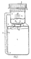
- Fig. 1 is a part-sectional side elevation of a container according to one embodiment of the invention, without the dispensing receptacle having a liner,
- Figs. 2 and 3 are each a fragmentary part-sectional elevation of the upper part of a container showing respectively a different embodiment of the invention in which the dispensing receptacle has a liner,
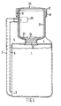
- Fig. 4 is a part-sectional side elevation of another embodiment of a container with an integral plug and liner component, and
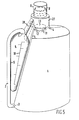
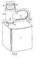
- Figs. 5 and 6 are perspective views of further embodiments of a container having a pouring head between the mouth and bottle throat, the receptacle providing a handle.
- The container, illustrated as a whole by Figs. 1, 4, 5 and 6, is made by known blow-moulding technology in which a tubular parison of thermoplastic material is extruded and then blown while pressed between a pair of dies to flatten and interweld opposed wall portions, around the hollow shapes of the container, receptacle and duct, and cut off any material excess to the required overall shape.
- As shown by Fig. 1, a
botle 1 is formed integrally with aduct 2 which extends, from abottom inlet 3, upwards externally alongside the bottle. Opposed wall portions of the container are, during moulding, flattened and interwelded to formweb portions duct 2 and a dispensingreceptacle 6, into which theduct 2 opens by anoutlet 7, integrally moulded to form the upper part of the container. - The
dispensing receptacle 6 is moulded with a full-width screw-threadedmouth 8, for aclosure cap 9, and the wall of thereceptacle 6 may also, as shown, be moulded withgraduation marks 10, to indicate the levels for given volumes of liquid to be dispensed. The material of the whole container is resilently flexible and preferably transparent or translucent. Suitable materials are polyethylene, which may be internally plasticised by copolymerisation, polypropylene or a butadienne-styrene copolymer. - Between the
bottle 1 and thedispensing receptacle 6, aneck 11 is moulded, and attention is drawn to the fact that theweb portions receptacle 6 with thebottle 1 andduct 2. The provision ofsuch webs 4, particularly in conjunction with theintegral duct 2 and its definingweb 5, renders stability and strength to the container in spite of it being made from resiliently flexible material. - The
neck 11 is moulded with anopen throat 12, a tubular blowing mandrel extending through the throat during the blow-moulding process, the mandrel having vents, to supply air to inflate thebottle 1 andreceptacle 6, respectively below and above thethroat 12. - After the
bottle 1 has been filled with liquid to be dispensed there is inserted, through thewide mouth 8 of thereceptacle 6, aplug 13 to close thethroat 12 to prevent leakage of fluid through the throat when thebottle 1 is squeezed to transfer liquid through theduct 2 into thereceptacle 6. - The
plug 13 may be made of a yielding material, such as a soft elastomer, so that it may be pressed into thethroat 12 and withdrawn therefrom, for which latter purpose it may be formed with arecess 14 spanned by abar 15 for engagement by a hooked withdrawing tool. - Alternatively, the
plug 13 may be non-removable, for example being of stiffly-flexible material so that it establishes a snap fit, or tight interference fit, in thethroat 12 and cannot be withdrawn without damage. For such purpose theplug 13 and/or the wall of thethroat 12 may be ridged or recessed for positive inter-engagement. - The
plug 13 may be sealed by the use of an adhesive or other applied sealing material. - In the embodiment of the invention illustrated by Fig. 2, the dispensing
receptacle 6 has aliner 16 the wall of which has a slight downward taper to fit tightly against the inside of thereceptacle 6 and seal off theduct outlet 7. The rim of theliner 16 has a surroundingskirt 17 with aninternal screwthread 18 to engage theexternal screwthread 19 around the rim of thereceptacle 6 and pull theliner 16 tightly to seal in thereceptacle 6 as the liner is screwed down. - As shown, the wall of the
liner 16 forms only a sleeve in thereceptacle 6 but the liner has a closedtop 20 so that, after removal, the liner may be inverted and used as a cup. - Alternatively the bottom of the
liner 16 could be closed, so that the liner forms a cup in its upright position, and the top of the liner may have a closure, such as a re-usable snap-fit cap or a disposable foil. - Fig. 3 shows an embodiment of the invention in which a
plug 13 has moulded therewith anextension 21 forming a liner which occupies the lower part of thereceptacle 6 and correspondingly reduces its capacity for dispensed liquid. - The
liner 21 is tapered, or may have a peripheral lip or bead around its rim, to seal in thereceptacle 6. - For one standard production size of container, a range of
liners 21 may be made to provide a choice of effective capacity, and consequent dose, of thedispensing receptacle 6. - The
integral plug 13 andliner 21 component is preferably a hollow moulding of resilient deformable plastics material. - Another embodiment with a plug and liner component is shown by Fig. 4, the
plug 13 being moulded integrally with aliner 22 to which it is connected by afrangible web 23. - The
liner 22 has a rim with ascrewthreaded skirt 17, and may also correspond in other respects with theliner 16 of Fig. 2, and the upper surface of theplug 13 has arecess 24 to receive a driving tool, such as a hexagonal key, for insertion of the plug and liner when the container has been filled. - By turning the plug and liner component as it is inserted into the
receptacle 6, thescrewthreads plug 13 to enter thethroat 12. Theweb 23 can be designed to withstand the torque involved as theplug 13 is driven into the throat but to shear, and leave theplug 13 in place, when theliner 22 is screwed from thereceptacle 6. - Alternatively or in addition, the rim or the mouth of the
liner 22 could be shaped, for example could be of hexagonal or other polygonal shape in plan, to receive a key or other tool for use in insertion or removal of the liner. Theweb 23 may be a continuous ring of thinner material or comprise spaced tabs of suitable angular extent to give, for an appropriate thickness, a required shear strength. - For a re-usable container, the
frangible web 23 is omitted so that the plug and liner component can be inserted and removed intact. In such case theliner 22 has aport 25 for admission of the liquid from theduct outlet 7. - Instead of being integrally moulded, a plug and liner could be made separately and joined, as by adhesive or a joint, such as an interference fit or a short, steep-pitched, screwthread, which will serve for driving in the
plug 13 but not for withdrawal. - As shown, the top of the
liner 22 has a removable snap-fit closure cap 26, but this is optional. - In the embodiment shown by Fig. 5, the
receptacle 6 is offset to one side of the upper part of the container and has the form of an asymmetrically conical cup inclined towards a pouringhead 27, between themouth 8 of the container and theneck 11 of the bottle which are offset towards the other side of the upper part of the container. Abranch 28 from the top of thereceptacle 6 opens into the pouringhead 27. Such a conical receptacle facilitates accurate dispensing of less than full doses, the graduation marks 10 having a more open scale towards the bottom. - As can be seen from Fig. 5, the
receptacle 6,branch 28 andweb portion 4 form a substantially triangular shoulder which serves as a handle for the container, thereceptacle 6 providing a relatively thick grip portion. - The upper end of the
duct 2 extends to the top of thereceptacle 6 so that itsoutlet 7 is directed downwardly through the top of the receptacle. This facilitates accurate dispensing of a full dose, any tilted attitude of the container not affecting the level of liquid determined by theduct outlet 7. - An alternative embodiment of the container with an offset pouring
head 27 is shown by Fig. 6, thereceptacle 6 in this case including the capacity of the pouring head and extending therefrom towards the other side of the upper part of the container. - In Fig. 6 also, the
receptacle 6 provides the grip portion of a handle on the shoulder of the container and theoutlet 7 from theduct 2 is directed downwardly through the top of the receptacle. - It will be apparent that all the embodiments illustrated enable a container to be made as a single blow-moulding, filled with liquid and then closed, by insertion of a plug, to close the throat, with or without a liner in the dispensing receptacle.
- Features described and illustrated with reference to one embodiment may be applied to other embodiments. In particular, a liner may be provided in the pouring
head 27 of the embodiments of Figs. 5 and 6, the pouring head providing access for insertion of theplug 13 in thethroat 12 and being capable of receiving a liner in the same way as the embodiments of Figs. 1 to 4.
Claims (10)
Priority Applications (1)
| Application Number | Priority Date | Filing Date | Title |
|---|---|---|---|
| AT82300987T ATE30356T1 (en) | 1981-03-02 | 1982-02-25 | DISPENSING CONTAINER. |
Applications Claiming Priority (6)
| Application Number | Priority Date | Filing Date | Title |
|---|---|---|---|
| GB8106546 | 1981-03-02 | ||
| GB8106546 | 1981-03-02 | ||
| GB8114203 | 1981-05-08 | ||
| GB8114203 | 1981-05-08 | ||
| GB8116550 | 1981-05-29 | ||
| GB8116550 | 1981-05-29 |
Publications (3)
| Publication Number | Publication Date |
|---|---|
| EP0060060A2 EP0060060A2 (en) | 1982-09-15 |
| EP0060060A3 EP0060060A3 (en) | 1983-10-05 |
| EP0060060B1 true EP0060060B1 (en) | 1987-10-21 |
Family
ID=27261129
Family Applications (1)
| Application Number | Title | Priority Date | Filing Date |
|---|---|---|---|
| EP82300987A Expired EP0060060B1 (en) | 1981-03-02 | 1982-02-25 | Dispensing container |
Country Status (8)
| Country | Link |
|---|---|
| US (1) | US4418843A (en) |
| EP (1) | EP0060060B1 (en) |
| AU (1) | AU548061B2 (en) |
| CA (1) | CA1178252A (en) |
| DE (1) | DE3277511D1 (en) |
| ES (1) | ES271966Y (en) |
| GB (1) | GB2093804B (en) |
| HK (1) | HK30390A (en) |
Families Citing this family (42)
| Publication number | Priority date | Publication date | Assignee | Title |
|---|---|---|---|---|
| GB2116522A (en) * | 1982-03-17 | 1983-09-28 | Bettix Ltd | Dispensing container for liquids |
| GB2129774B (en) * | 1982-11-05 | 1985-11-13 | Bettix Ltd | Dispensing container |
| US4600130A (en) * | 1983-09-29 | 1986-07-15 | Libit Sidney M | Squeeze pressure dispenser with integral siphon tube |
| GB8412297D0 (en) * | 1984-05-14 | 1984-06-20 | Unilever Plc | Liquid dispensing container |
| GB8528138D0 (en) * | 1985-11-14 | 1985-12-18 | Plaspharm Uk Ltd | Dosage device |
| ES2033833T3 (en) * | 1986-03-27 | 1993-04-01 | Unilever N.V. | DISPENSING CONTAINERS. |
| US4811869A (en) * | 1987-06-25 | 1989-03-14 | Roger Tremblay | Powder dispenser |
| AU5378794A (en) * | 1992-10-28 | 1994-05-24 | Innovative Engineering Limited | An improved volumetric metering device |
| US5556011A (en) * | 1993-12-13 | 1996-09-17 | Jennings; Robert M. | Measuring container |
| USD379063S (en) * | 1996-07-25 | 1997-05-06 | Gold Eagle Co. | Dosage bottle |
| DE59700882D1 (en) * | 1997-05-02 | 2000-01-27 | Soplar Sa | Bottle, especially for cleaning toilet bowls |
| US5884816A (en) * | 1997-08-01 | 1999-03-23 | Hinze; John F. | Liquid measuring device and method of using same |
| GB2340236B (en) * | 1998-06-20 | 2003-03-26 | Sensalyse Ltd | Analysis of liquid samples |
| US6330960B1 (en) * | 1999-06-04 | 2001-12-18 | Mcneil-Ppc, Inc. | Squeeze dispenser |
| US6213358B1 (en) * | 1999-08-16 | 2001-04-10 | Jeffrey M. Libit | Molded bottle with inclined spray tube |
| AU7306400A (en) * | 1999-11-18 | 2001-05-30 | Alpla Werke Alwin Lehner Gmbh & Co. Kg | Squeezable bottle comprising a dosing chamber |
| US6290102B1 (en) | 2000-03-31 | 2001-09-18 | Robert Michael Jennings | Liquid measuring and dispensing container |
| GB2369609B (en) * | 2000-11-04 | 2006-02-08 | Bettix Ltd | Bottle |
| GB2389098A (en) * | 2002-05-08 | 2003-12-03 | Craig Driver | Dispensing container |
| US20040116035A1 (en) * | 2002-11-14 | 2004-06-17 | Mark Fitchmun | Soap dispenser with reservoir for bubble wand |
| AU2003304227A1 (en) * | 2003-06-24 | 2005-01-04 | Suttern Finanziaria S.P.A. | Dispensing container |
| USD508855S1 (en) | 2003-10-03 | 2005-08-30 | Gold Eagle Co. | Container |
| USD510028S1 (en) | 2003-11-21 | 2005-09-27 | Gold Eagle Co. | Bottle |
| US7467735B2 (en) * | 2004-10-29 | 2008-12-23 | Minuteman International, Inc. | Proportioning container |
| EP1835997B1 (en) | 2004-12-16 | 2012-06-13 | Saint-Gobain Abrasives, Inc. | Liquid supply cup and liner assembly for spray guns |
| US11040360B2 (en) | 2006-06-20 | 2021-06-22 | Saint-Gobain Abrasives, Inc. | Liquid supply assembly |
| DK2029285T3 (en) | 2006-06-20 | 2013-03-11 | Saint Gobain Abrasives Inc | The liquid supply device |
| US20080067195A1 (en) * | 2006-09-15 | 2008-03-20 | Jennings Robert M | Measuring and dispensing container |
| USD564364S1 (en) | 2006-12-20 | 2008-03-18 | Hasbro, Inc. | Fluid dispensing bottle |
| CN102046482A (en) * | 2008-06-03 | 2011-05-04 | 辛福寅 | Quantitative measurement container |
| US20110204086A1 (en) * | 2010-02-24 | 2011-08-25 | Karam Anthony A | Refillable Container with a Graduated Neck Extension |
| US20120018458A1 (en) | 2010-07-26 | 2012-01-26 | Ecolab Usa Inc. | Metered dosing bottle |
| FR2963423B1 (en) * | 2010-07-27 | 2013-07-26 | Pont Emballage | ASSAY DEVICE |
| CA2835088C (en) | 2011-05-06 | 2018-01-16 | Saint-Gobain Abrasives, Inc. | Paint cup assembly with an extended ring |
| US8974744B2 (en) * | 2011-06-08 | 2015-03-10 | Dan Llewllyn | Bottle for disinfecting toothbrush |
| ES2739299T3 (en) | 2011-06-30 | 2020-01-30 | Saint Gobain Abrasives Inc | Paint container set |
| MX2014007887A (en) | 2011-12-30 | 2014-10-06 | Saint Gobain Abrasives Inc | Convertible paint cup assembly with air inlet valve. |
| US10232971B2 (en) * | 2013-03-08 | 2019-03-19 | Robert M. Jennings | Measuring and dispensing container |
| GB2519206B (en) | 2013-08-17 | 2015-11-25 | Mwv Slatersville Llc | One-piece squeeze-to-dose dispensing closure |
| USD865442S1 (en) | 2017-03-10 | 2019-11-05 | J. A. Products, Llc | Novelty beverage drinking device |
| CN107323783A (en) * | 2017-07-06 | 2017-11-07 | 安徽三环水泵有限责任公司 | A kind of new pump oil bottle |
| GB201720561D0 (en) * | 2017-12-10 | 2018-01-24 | Simard Jo-Anne | Fluid measuring and dispensing device |
Citations (1)
| Publication number | Priority date | Publication date | Assignee | Title |
|---|---|---|---|---|
| EP0010965A1 (en) * | 1978-11-02 | 1980-05-14 | Bettix Limited | A squeeze-bottle, liquid-dispensing container |
Family Cites Families (9)
| Publication number | Priority date | Publication date | Assignee | Title |
|---|---|---|---|---|
| DE865810C (en) | 1951-06-14 | 1953-02-05 | Oscar Pfister | Fluid meter |
| US3141574A (en) * | 1963-04-22 | 1964-07-21 | Robert J Donoghue | Container for dispensing selected quantities of fluid |
| US3396875A (en) * | 1966-11-25 | 1968-08-13 | Richard P Matthews | Container with integral measuring chamber |
| FR2173838A1 (en) * | 1972-02-29 | 1973-10-12 | Levenez Yves | |
| US4077547A (en) * | 1976-02-02 | 1978-03-07 | Donoghue Robert J | Measuring and dispensing apparatus |
| US4105142A (en) * | 1976-10-07 | 1978-08-08 | Morris Jr Harold K | Dispensing device for fluid substances |
| US4106673A (en) * | 1977-03-21 | 1978-08-15 | Donoghue Robert J | Apparatus for measuring and dispensing liquid |
| NZ193060A (en) * | 1979-03-07 | 1984-07-06 | Wellcome Found | Squeeze bottle dispenser with integral measuring chamber |
| US4298038A (en) * | 1979-09-21 | 1981-11-03 | Jennings J Thomas | Technique and device for measuring fluids including finger valve and filler mechanism |
-
1982
- 1982-02-23 CA CA000396807A patent/CA1178252A/en not_active Expired
- 1982-02-23 US US06/351,461 patent/US4418843A/en not_active Expired - Lifetime
- 1982-02-24 AU AU80759/82A patent/AU548061B2/en not_active Ceased
- 1982-02-25 EP EP82300987A patent/EP0060060B1/en not_active Expired
- 1982-02-25 DE DE8282300987T patent/DE3277511D1/en not_active Expired
- 1982-02-26 GB GB8205691A patent/GB2093804B/en not_active Expired
- 1982-03-02 ES ES1982271966U patent/ES271966Y/en not_active Expired
-
1990
- 1990-04-19 HK HK303/90A patent/HK30390A/en not_active IP Right Cessation
Patent Citations (1)
| Publication number | Priority date | Publication date | Assignee | Title |
|---|---|---|---|---|
| EP0010965A1 (en) * | 1978-11-02 | 1980-05-14 | Bettix Limited | A squeeze-bottle, liquid-dispensing container |
Also Published As
| Publication number | Publication date |
|---|---|
| ES271966U (en) | 1984-01-16 |
| AU548061B2 (en) | 1985-11-21 |
| CA1178252A (en) | 1984-11-20 |
| GB2093804B (en) | 1985-05-15 |
| DE3277511D1 (en) | 1987-11-26 |
| US4418843A (en) | 1983-12-06 |
| HK30390A (en) | 1990-04-27 |
| AU8075982A (en) | 1982-09-09 |
| EP0060060A2 (en) | 1982-09-15 |
| GB2093804A (en) | 1982-09-08 |
| ES271966Y (en) | 1984-08-01 |
| EP0060060A3 (en) | 1983-10-05 |
Similar Documents
| Publication | Publication Date | Title |
|---|---|---|
| US4418843A (en) | Single-mouth squeeze-bottle dispensing container | |
| EP3261943B1 (en) | Inverted bottle dispensing systems and methods | |
| CA2064905C (en) | Device for dispensing flowing substances | |
| US5358148A (en) | Urine collection container | |
| EP0010965B1 (en) | A squeeze-bottle, liquid-dispensing container | |
| US4061253A (en) | Metering dispensing bottle | |
| US5533553A (en) | Container set comprising at least two containers | |
| EP0161715B1 (en) | Liquid-dispensing container | |
| EP1383687B1 (en) | Container for dispensing spill-resistant formulations | |
| EP0089978A4 (en) | Bottle closure and method of making same. | |
| US4576602A (en) | Blow molded container with integral administration port | |
| US5746260A (en) | Container set comprising at least two containers | |
| EP1120354B1 (en) | Package comprising a closure for a liquid container and a refill means, and a method for refilling the package | |
| JP2004203467A (en) | Measuring cap | |
| JPS6050672B2 (en) | distribution container | |
| FI71910B (en) | FOERDELNINGSBEHAOLLARE | |
| CA1146507A (en) | Dispensing container | |
| WO2017214354A1 (en) | Cap for dispensing a metered volume of liquid | |
| CN121044168A (en) | Quantitative dispensing container | |
| EP0552043A1 (en) | Dispensing device | |
| JP2003191971A (en) | Bag-shaped container with straw | |
| GB2129774A (en) | Dispensing container | |
| JP2605237Y2 (en) | Tube container | |
| JPH0326134Y2 (en) | ||
| JPH0640132Y2 (en) | Cartridge for cream dispenser |
Legal Events
| Date | Code | Title | Description |
|---|---|---|---|
| PUAI | Public reference made under article 153(3) epc to a published international application that has entered the european phase |
Free format text: ORIGINAL CODE: 0009012 |
|
| AK | Designated contracting states |
Designated state(s): AT BE CH DE FR GB IT LU NL SE |
|
| PUAL | Search report despatched |
Free format text: ORIGINAL CODE: 0009013 |
|
| AK | Designated contracting states |
Designated state(s): AT BE CH DE FR GB IT LI LU NL SE |
|
| 17P | Request for examination filed |
Effective date: 19840317 |
|
| ITF | It: translation for a ep patent filed | ||
| RAP1 | Party data changed (applicant data changed or rights of an application transferred) |
Owner name: BETTIX LIMITED |
|
| GRAA | (expected) grant |
Free format text: ORIGINAL CODE: 0009210 |
|
| AK | Designated contracting states |
Kind code of ref document: B1 Designated state(s): AT BE CH DE FR IT LI LU NL SE |
|
| REF | Corresponds to: |
Ref document number: 30356 Country of ref document: AT Date of ref document: 19871115 Kind code of ref document: T |
|
| REF | Corresponds to: |
Ref document number: 3277511 Country of ref document: DE Date of ref document: 19871126 |
|
| ET | Fr: translation filed | ||
| PLBE | No opposition filed within time limit |
Free format text: ORIGINAL CODE: 0009261 |
|
| STAA | Information on the status of an ep patent application or granted ep patent |
Free format text: STATUS: NO OPPOSITION FILED WITHIN TIME LIMIT |
|
| 26N | No opposition filed | ||
| ITTA | It: last paid annual fee | ||
| EPTA | Lu: last paid annual fee | ||
| EAL | Se: european patent in force in sweden |
Ref document number: 82300987.3 |
|
| PGFP | Annual fee paid to national office [announced via postgrant information from national office to epo] |
Ref country code: BE Payment date: 20001207 Year of fee payment: 20 |
|
| PGFP | Annual fee paid to national office [announced via postgrant information from national office to epo] |
Ref country code: FR Payment date: 20001229 Year of fee payment: 20 |
|
| PGFP | Annual fee paid to national office [announced via postgrant information from national office to epo] |
Ref country code: LU Payment date: 20010129 Year of fee payment: 20 |
|
| PGFP | Annual fee paid to national office [announced via postgrant information from national office to epo] |
Ref country code: DE Payment date: 20010131 Year of fee payment: 20 |
|
| PGFP | Annual fee paid to national office [announced via postgrant information from national office to epo] |
Ref country code: CH Payment date: 20010213 Year of fee payment: 20 |
|
| PGFP | Annual fee paid to national office [announced via postgrant information from national office to epo] |
Ref country code: SE Payment date: 20010215 Year of fee payment: 20 |
|
| PGFP | Annual fee paid to national office [announced via postgrant information from national office to epo] |
Ref country code: AT Payment date: 20010227 Year of fee payment: 20 |
|
| PGFP | Annual fee paid to national office [announced via postgrant information from national office to epo] |
Ref country code: NL Payment date: 20010228 Year of fee payment: 20 |
|
| BE20 | Be: patent expired |
Free format text: 20020225 *BETTIX LTD |
|
| PG25 | Lapsed in a contracting state [announced via postgrant information from national office to epo] |
Ref country code: LI Free format text: LAPSE BECAUSE OF EXPIRATION OF PROTECTION Effective date: 20020224 Ref country code: CH Free format text: LAPSE BECAUSE OF EXPIRATION OF PROTECTION Effective date: 20020224 |
|
| PG25 | Lapsed in a contracting state [announced via postgrant information from national office to epo] |
Ref country code: NL Free format text: LAPSE BECAUSE OF EXPIRATION OF PROTECTION Effective date: 20020225 Ref country code: LU Free format text: LAPSE BECAUSE OF EXPIRATION OF PROTECTION Effective date: 20020225 Ref country code: AT Free format text: LAPSE BECAUSE OF EXPIRATION OF PROTECTION Effective date: 20020225 |
|
| REG | Reference to a national code |
Ref country code: CH Ref legal event code: PL |
|
| EUG | Se: european patent has lapsed |
Ref document number: 82300987.3 |
|
| NLV7 | Nl: ceased due to reaching the maximum lifetime of a patent |
Effective date: 20020225 |