EP0060014A1 - Modular, self-supporting flight of stairs - Google Patents
Modular, self-supporting flight of stairs Download PDFInfo
- Publication number
- EP0060014A1 EP0060014A1 EP82300298A EP82300298A EP0060014A1 EP 0060014 A1 EP0060014 A1 EP 0060014A1 EP 82300298 A EP82300298 A EP 82300298A EP 82300298 A EP82300298 A EP 82300298A EP 0060014 A1 EP0060014 A1 EP 0060014A1
- Authority
- EP
- European Patent Office
- Prior art keywords
- stringer
- side plate
- stairs
- plate
- unit
- Prior art date
- Legal status (The legal status is an assumption and is not a legal conclusion. Google has not performed a legal analysis and makes no representation as to the accuracy of the status listed.)
- Granted
Links
Images


Classifications
-
- E—FIXED CONSTRUCTIONS
- E04—BUILDING
- E04F—FINISHING WORK ON BUILDINGS, e.g. STAIRS, FLOORS
- E04F11/00—Stairways, ramps, or like structures; Balustrades; Handrails
- E04F11/02—Stairways; Layouts thereof
- E04F11/022—Stairways; Layouts thereof characterised by the supporting structure
- E04F11/035—Stairways consisting of a plurality of assembled modular parts without further support
-
- E—FIXED CONSTRUCTIONS
- E04—BUILDING
- E04F—FINISHING WORK ON BUILDINGS, e.g. STAIRS, FLOORS
- E04F11/00—Stairways, ramps, or like structures; Balustrades; Handrails
- E04F11/02—Stairways; Layouts thereof
- E04F11/104—Treads
- E04F11/1041—Treads having means to adjust the height, the depth and/or the slope of the stair steps
Definitions
- the present invention relates to a modular, self-supporting flight of stairs comprising at least two pairs of stringer units each acting as a support for a thread-step.
- the invention also relates to the stringer units used for the fabrication of this flight of stairs.
- the object of the present invention is to provide the new type of stringer unit for the fabrication of a modular, self-supporting flight of stairs, whose structure advantageously permits to overcome the above mentioned drawbacks.
- the object of the present invention is to provide a new type of stringer unit for the fabrication of a modular, self-supporting flight of stairs which, due to their angular structure, give an excellent lateral stability to the stairs fabricated therefrom and which, due to their installation by means of bolts or rivets passing through a plurality of punched holes that may fit one inside the other, substantially reduce the shearing forces undergone by the bolts or rivets in use and therefore give to the stairs fabricated therefrom an excellent ability of supporting any heavy load.
- Another object of the present invention is to provide a modular, self-supporting flight of stairs comprising at least two pairs of stringer units of the above mentioned type, each pair acting as a support for a thread step.
- the stringer unit for the fabrication of modular, self-supporting flight of stairs comprises a vertical side plate provided with an horizontal upper flange, and a vertical front plate defining a rectangular dihedron with the side plate.
- the front plate is also provided with an horizontal, upper flange defining together with the upper flange of the side plate, a rigid L-shaped support very stable in use for supporting one end of the step thread.
- the stringer unit according to the invention gives an excellent lateral stability to the stairs once the flight has been erected, since each step is fixed not only by two parallel rows of nails or rivets at the vicinity of its ends but also by a third row of nails or bolts perpendicular to the two parallel rows.
- the stringer unit according to the invention also comprises a small fixation plate integrally extending the side plate in the same plane as, or in a plane parallel to the plane of this side plate.
- This fixation plate is positioned so as to come into contact with the surface of the side plate of another, upper or lower stringer unit.
- the surface of the fixation plate and the surface of the side plate of the unit with which a fixation plate of a further, upper or lower stringer unit comes into contact, are each provided at least one punched hole positioned in such a manner as to be in front of a corresponding hole punched in the same direction through the surface of the fixation plate or the surface of the side plate of the further, upper or lower stringer unit for allowing fixation of both units together.
- the fixation plate integrally extends the rear upper end of the lateral side in a plane extending rearwardly, and parallel to the plane of the side plate.
- the fixation plate extends vertically above the upper edge of the side plate so as to come into contact with the surface of the lower front end of the stringer unit immediately superior thereto.
- the fixation plate integrally extends the front lower end of the side plate in a plane extending rearwardly, and parallel to the plane of the side plate.
- the fixation plate extends in front of the side plate so as to come into contact with the surface to the rear upper end of the side plate of the stringer unit immediately inferior thereto, just under the upper flange thereof.
- the stringer unit is made of two separate pieces vertically adjustable with respect to each other in order to allow adjustment of the total height of each step.
- This adjustment is obtained by a set of double slots provided in each piece and a pair of bolts and nuts screwed at an intersection of the sets of slots in order to connect both pieces together.
- the set of double slots of the upper piece extends in one inclined direction opposite to the direction of the set of double slots of the lower piece so that any movement of the bolts along one set of slots in one direction is automatically compensated by a corresponding movement of the bolts in the other direction along the other set of double slots of the other piece.
- the modular, self-supporting flight of stairs comprises at least two pairs of stringer units as defined hereinabove.
- Each pair of stringer units acts as a support for a thread-step.
- the stringer units of each pair are fixed to the corresponding stringer units of the other pair which is immediately inferior or superior thereto by riveting or bolting the fixation plates of the units of one pair to the side plates of the units of the other pair, respectively.
- the flight of stairs further comprises two holding pieces each in the shape of a rectangular dihedron having one of their planes provided with at least one punched hole. These holding pieces are fixed by their planes provided with at least one punched hole, to the fixation plates or side plates of the stringer units supporting the upper step of the stairs. These holding pieces are especially used for firmly maintaining the upper end of the stairs onto a suitable support by fixation of their other planes onto this support. If this is necessary, a vertical connecting piece can be used between each holding piece and the support.
- the above described flight of stairs further comprises two reinforcing pieces having substantially the same shape as the above described, holding pieces.
- These reinforcing pieces can be fixed by riveting or bolting their planes provided with at least one punched hole to the fixation plates and side plates of two pairs of stringer units attached to each other for supporting two adjacent steps.
- These reinforcing pieces are advantageously used for laterally reinforcing the flight of stairs by fixation of their other planes to the ends of an horizontal rod or beam extending across, and under, the steps of the stairs.
- the stringer units of each pair are symmetrical with respect to a vertical plane passing through the middle of the stairs.
- the front side of each unit preferably extends towards the middle of the stairs.
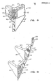
- FIGS 1, 3 and 5 of the drawings show a flight of stairs 1 which is modular and self-supporting.
- the flight of stairs 1 is modular since it comprises a plurality of identical stringer units 3 acting as supports for a plurality of thread-steps 7.
- the flight of stairs 1 is also self-supporting since it does not require lateral beams for supporting its stringer-units, the mere assembly of the modular,units 3 all together being sufficient for giving enough rigidity to the stairs for supporting one or several persons going up or down the steps 7.
- the flight of stairs 1 comprises a first pair of stringer units 5 acting as support for the first step of the stairs, and a plurality of other pairs of stringer units 3 and 3' each acting as a support for a step from the first step to the floor P to which the stairs lead.
- the stringer units 3 and 3' of each pair are advantageously fabricated and orientated to be symmetrical with respect to a vertical plane passing through the middle of the stairs. It should be noted that this symmetrical arrangement is not essential since use could also be made of stringer units 3 and 3' that would be identical to each other instead of being symmetrical with respect to a vertical plane, with the same positive result although the general aspect of the stairs would be unbalanced.
- Each stringer unit used for the fabrication of the flight of stairs 1 comprises a vertical side plate 11 provided with an horizontal, upper flange 13, and a vertical front plate 21 defining a rectangular dihedron with the side plate 11.
- the front plate 21 is also provided with an horizontal, upper flange 23 which extends in the same plane as the horizontal flange 13 of the side plate 11 in order to define together with this flange 13 a rigid, L-shaped support very stable in use and on which can be fixed one end of the step 7.
- the horizontal flanges 13 and 23 may comprise a plurality of holes 15 and 25 provided for receiving bolts 71 passing through the end of the step 7.
- the lower extremity of these bolts 71 can be screwed directly into the holes 15 and 25 if these holes are threaded or they can be fixed with nuts 73 as shown on Figure 1.
- each stringer unit 3 provides the L-shaped, horizontal support provided by each stringer unit 3 to the end of each step 7, the flight of stairs 1 exhibits an excellent lateral stability since each step 7 is fixed by its two lateral edges and a portion of its front edge, that is along two perpendicular axes. It should be noted that this particular arrangement is not shown in any prior art references of which the Applicant is aware.
- Each stringer unit 3 also comprises a fixation plate 27 integrally extending the side plate 11 in a plane that can be identical to the plane of the side plate 11, or, as shown, in a plane extending rearwardly and parallel to the plane of the side plate 11.
- the fixation plate 27 integrally extends the front lower end of the side plate 11 in a plane extending rearwardly and parallel to the plane of this side plate, this set back position defining a vertical edge 31.
- the fixation plate 27 extends forwards in front of the side plate 11 so as to come into contact with the surface of the rear upper end of the side plate 11 of the stringer unit 3 which is immediately inferior thereto, just under the horizontal flange 13 of this side plate.
- the surface of the fixation plate 27 is provided with two punched holes 29.
- the surfaces of the side plate 11 and the stringer units 3 with which the fixation plate 27 of the stringer unit 3 immediately superior thereto to come into contact, is also provided with two holes 19 punched in the same direction as the holes 29 and placed in such a manner as to be in cooperative relationship with respect to these holes 29.
- the fixation plate 27 and the side plate 11 preferably each comprise two holes.
- the number of holes is not an essential feature of the invention and that only one single hole is more than two holes 19 or 29 could be used if desired.
- the holes 19 and 29 are positioned so as to allow fixation of the stringer units to each other by riveting or bolting.
- the collars 33 and 35 of the punched holes 19 and 29 engaged one inside the other advantageously support the load and transmit this load directly to the side plates 11 of the stringer units instead of transmitting it to the bolts or rivets 37 inserted into these holes.
- these bolts or rivets 37 are less and even no more subjected to vertical shearing forces, as these forces act only onto the collars 35 and 37 of the punched holes.
- the improved reinforcement of the flight of stairs is furthermore completed by the vertical edge 31 formed at the connection of the fixation plate 27 with the side plate 11 of each stringer unit 3.
- the rear end of the side plate 11 comes into contact with, and bears against the edge 31 when the bolts or rivets 37 are fixed.
- This bearing of the lower stringer unit 3 against the upper stringer unit 3 along this edge 31 is particularly interesting since it increases the supporting capacity of the flight of stairs in a very efficient and simple manner.
- each stringer unit 3 is made of one single piece.
- the lower edge 17 of the side plate 11 is advantageously inclined from the front to the rear of each stringer unit at such an angle that this lower edge 17 extends in line the lower edge 17 of the side plate of the stringer unit immediately superior or inferior thereto once this other stringer unit has been fixed, while dissimulating the fixation plate.
- the stringer units 5 that support the first edge of the stairs are structurally identical to the stringer units 3 that are superior thereto except that, on one end, each unit 5 does not comprise a fixation plate as it has not to be fixed to a lower unit and, on the other end, the lower edge 57 of its side plate 51 is not inclined but rather horizontal in order to increase the surface of contact of this stringer unit 5 with the ground or floor on which it lays.
- the stringer unit 5 comprises a side plate 51 provided with an upper edge 53 and a front plate 61 provided with an upper edge 63.
- the upper edges 53 and 63 extend at the same level and are each provided with holes 55 whose function is identical to that of the holes 15 and 25 previously described in connection with the stringer units 3.
- the stringer unit 5 also comprises, as the stringer unit 3, two punched holes 59 in the rear surface of its plate 51, to allow bolting or riveting of the fixation plate 27 of the stringer unit 3 that is immediately superior thereto.
- the above-described flight of stairs 1 lays by the lower ends of its lower units 5 directly onto the ground S. It is compulsory however that the upper ends of this flight be fixed to the floor P or to the vertical edge of the floor to which the flight of stairs leads.
- each holding piece 9 and 9' each having the shape of a rectangular dihedron having one of its plane 91 provided with two punched holes 99 positioned so as to be in front of the holes 19 of the last stringer units 3 and 3' respectively.
- Each holding piece 9 is screwed or bolted by its plane 91 provided with a punched holes 99 directly to the side plate 11 of one of the stringer units 3 supporting the last step of the stairs.
- the holding piece 9 is also fixed by its other plane 93 directly to the vertical edge surface of the floor P at a suitable level.
- the means used for fixing the plane 93 of the holding piece 9 directly to the vertical edge of the floor P can be of any standard type and accordingly these means will not be described hereinafter in detail.
- the plane 93 can be provided with holes in which the above mentioned fixing means may be inserted.
- the number of punched holes 99 and the size of the holding pieces 9 of course depend on the number of punched holes and the size of each stringer unit 3.
- the holding pieces 9 and 9' are structurally symmetrical and accordingly they do not need be specifically fabricated in view of being used on the left or right side of the stairs, as are the stringer units 3 and 3'.
- This vertical connecting piece 95 consists of a simple, elongated steel plate perforated with holes 97 regularly spaced apart and it can be fixed by means of bolts the plane 93 of the holding piece 9 in order to upwards this plane 93 to the desired level where it can then be fixed to the floor P by any conventional means such as fixation anchors inserted through the holes 97.
- the holding pieces 9 that have been described hereinabove, can be used not only for fixing the last pair of stringer units 3 and 3' of the flight of stairs 1 to the floor P, but also for improving the lateral stability of this flight of stairs when this is needed. In this case, the pieces 9 are not used anymore for holding the assembly but for reinforcing it.
- the lateral stability of the flight of stairs 1 can be reinforced by using two pieces 9 in combination with a horizontal rod or beam 41.
- the reinforcing pieces 9 are fixed by riveting or bolting their plane provided with punched holes, directly to the fixation plates 27 and the side plates 11 of two pairs of stringers units acting as supports for two adjacent steps at substantially half-way from the top of the stairs or at equal interval.
- the reinforcing pieces 9 are then fixed to each other by the rod or beam 41 which then may keep the lateral sides of the flight of stairs 1 in parallel relationship and to avoid that these lateral sides separate from each other or laterally bends.
- the lateral stability of both sides of the flight of stairs 1 is obtained by the steps 7.
- the use of one or several holding rod 41 substantially improves the general structural and resistance of the stairs.
- the reinforcing and holding pieces are advantageously identical to each other as it has been described hereinabove.
- At least one pair of stringer units whose heights are adjustable may be provided in order to compensate any slack that could be produced when assembling the flight of stairs 1 onto the premises or for compensating any recess in the ground or floor onto which the flight of stairs lays.
- a pair of stringer units 103 whose general structure and function are identical to the structure and function of the stringer units 3 except that each stringer unit 103 is made of two pieces vertically adjustable with respect to each other instead of being made of one piece.
- the lower piece of the step 103 comprises a vertical side plate 111 and a vertical front plate 121 forming a rectangular dihedron with the side plate 111.
- the lower front end of side plate 111 is integrally extended by a fixation plate 127 provided with two punched holes 129, to give to the unit the same structure as that previously described for each one-piece made, stringer unit 3.
- the upper piece of the adjustable stringer unit 103 comprises a vertical side plate 111' which is provided with an horizontal upper flange 113, and a vertical front plate 121' forming a rectangular dihedron with a side plate 111'.
- the front plate 121' is also provided with a horizontal upper flange 123 which extends in the same plane as the horizontal flange 113 of the side plate 111' in order to define together with the flange 113 a rigid L-shaped support very stable in use for supporting one of the steps 7.
- the vertical plates 111' et 121' are sized to face, and come into contact with, the vertical plates 111 and 121 of the lower piece. This particular structure allows vertical sliding of the upper piece of the stringer unit 103 with respect to the lower piece of this unit for increasing or reducing the total front surface defined by the plates 121 and 121' and the total side surface defined by the plates 111 et 111'.
- a first set of two slots 143 both extending in one inclined direction is provided in the upper piece of the stringer unit 103.
- Another set of two slots 145 extending in an inclined direction opposite to that of the slot 143 is provided in the lower piece as clearly shown on Figures 7 and 8.
- the two set of slots 143 and 145 are positioned with respect to each other in such manner that the slots of one set comes across the slots of the other set to allow insertion of fixation bolts 147 at their respective crossings.
- the main advantage of using such a set of double slots is to provide firm holding of both pieces of the stringer unit 103 once these pieces are fixed to each other. Indeed, the inclination of the slots and the fact that each piece is in the shape of a dihedron whose surfaces are parallel and adjacent to the surfaces of the other piece, causes the pieces to interlock in an automatic manner.
- fixation plate 227 extends vertically above the horizontal flange 213 of the side plate 211 of the stringer unit 203 so as to come to contact with the surface of the lower front end of the stringer unit immediately superior thereto.
- stringer units 303 whose vertical side plate 311 is not integrally extended by an horizontal upper flange as described hereinabove but is rather cut at angle to define an upper edge 313, which extends slightly downwards to the rear.
- an easily, attachable, support member 331 is used.
- This member 331 comprises a vertical plate 335 provided with at least two and preferably three pairs of punched holes 337 positioned in such a manner that each pair of holes 337 is vertically spaced apart with respect to each other(s) and is connectable to the pair of holes 319 used for attaching the stringer unit 303 to the one immediately superior thereto.
- the member 331 also comprises an horizontal plate 333 integrally extending the vertical plate 335, for supporting the end of the step that will be mounted onto the stringer. This horizontal plate may be provided with a hole to ease the fixation of the step, as shown on Figure 10.
- the members 331 are rigidly attached to their respective stringer units to provide rigid supports to the steps and laterally reinforce the stairs in the same manner as the upper flanges of the side plates 311 would do.
- This attachment is carried out by application of the member plate 335 against the plate 311 of the unit with one selected pair of holes 337 in front of the holes 319 (and 329) and introduction of the fixation bolts used for fixing the stringer units together through the holes 337, 329 and 319.
- this particular embodiment does not require any additional elements for attaching or fixing the structural members of the stringer units altogether. Moreover, this particular embodiment advantageously makes the level of each step adjustable whenever necessary, thanks to the various pairs of holes 337 that do not extend at the same level and may therefore be selected to raise or lower the rear parts of the steps whenever is necessary.
Abstract
Description
- The present invention relates to a modular, self-supporting flight of stairs comprising at least two pairs of stringer units each acting as a support for a thread-step. The invention also relates to the stringer units used for the fabrication of this flight of stairs.
- Numerous modular, self-supporting flights of stairs of different structure are already known and commercially available in the market for arranging in a very fast manner, any kind of building space comprising floors at different levels. Examples of such already known flights of stairs are disclosed and claimed in U.S. Patents Nos. 2,593,683 of 1952; 2,724,466 of 1955; 2,760,239 of 1956 and 3,196,397 of 1965 and Canadian Patent No. 600,821 of 1960.
- If the flights of stairs disclosed in these patents all have the advantages of being of a relatively simple structure and therefore installable in a very fast manner even by a not specialized labour, however they all have also the drawback of being not very stable against lateral pressure because of the relative thinness of their stringers even when these stringers are provided with reinforcing flanges, and not very resistant with respect to the load they can support because each of their stringers is fixed to the stringer immediately inferior or superior thereto by means of bolts or rivets that are subject in use to very substantial shearing forces.
- Thus, one can see that the bolts used for fixing the modular stringers of the flight of stairs disclosed in U.S. Patent No. 2,593,683 are permanently subject to vertical shearing forces while the bolts used for fixing the modular stringers of the flight of stairs disclosed in U.S. Patents Nos. 2,724,466 and 3,196,997 are also subject to shearing forces that are applied to the bolts in an inclined plane corresponding to the plane of the stairs. In a similar manner, the screws used for fixing the modular steps of the flight of stairs disclosed in U.S. Patent No. 2,760,239 to their supporting, wood stringers are subject to vertical shearing forces as are the nails used for fixing the steps of the stairs disclosed in Canadian Patent No. 600821 to their wood stringers.
- The object of the present invention is to provide the new type of stringer unit for the fabrication of a modular, self-supporting flight of stairs, whose structure advantageously permits to overcome the above mentioned drawbacks.
- More especially, the object of the present invention is to provide a new type of stringer unit for the fabrication of a modular, self-supporting flight of stairs which, due to their angular structure, give an excellent lateral stability to the stairs fabricated therefrom and which, due to their installation by means of bolts or rivets passing through a plurality of punched holes that may fit one inside the other, substantially reduce the shearing forces undergone by the bolts or rivets in use and therefore give to the stairs fabricated therefrom an excellent ability of supporting any heavy load.
- Another object of the present invention is to provide a modular, self-supporting flight of stairs comprising at least two pairs of stringer units of the above mentioned type, each pair acting as a support for a thread step.
- The stringer unit for the fabrication of modular, self-supporting flight of stairs according to the invention comprises a vertical side plate provided with an horizontal upper flange, and a vertical front plate defining a rectangular dihedron with the side plate. The front plate is also provided with an horizontal, upper flange defining together with the upper flange of the side plate, a rigid L-shaped support very stable in use for supporting one end of the step thread.
- Due to the very particular shape formed by the upper flanges of both sides plates, the stringer unit according to the invention gives an excellent lateral stability to the stairs once the flight has been erected, since each step is fixed not only by two parallel rows of nails or rivets at the vicinity of its ends but also by a third row of nails or bolts perpendicular to the two parallel rows.
- The stringer unit according to the invention also comprises a small fixation plate integrally extending the side plate in the same plane as, or in a plane parallel to the plane of this side plate. This fixation plate is positioned so as to come into contact with the surface of the side plate of another, upper or lower stringer unit. The surface of the fixation plate and the surface of the side plate of the unit with which a fixation plate of a further, upper or lower stringer unit comes into contact, are each provided at least one punched hole positioned in such a manner as to be in front of a corresponding hole punched in the same direction through the surface of the fixation plate or the surface of the side plate of the further, upper or lower stringer unit for allowing fixation of both units together.
- The fact that the holes used for fixing each stringer unit to the other stringer unit immediately superior or inferior thereto is punched, is of a great interest since it provides some engagement of the portion of the holes punched outwards one inside the other during the riveting and bolting step and thus an improved reinforcement of the flight of stairs against the vertical shearing forces. Indeed, it can be easily understood that the portions of the holes punched outwards that engage one inside the other, cooperate to support the load and to transmit this load directly to the side plate of the stringer units instead of transmitting it to the holts or rivets passing through the holes. Accordingly, the bolts or rivets used for fixing the stringer units together are much less, and even no more, subject to vertical shearing forces.
- In accordance with a preferred embodiment of the invention, the fixation plate integrally extends the rear upper end of the lateral side in a plane extending rearwardly, and parallel to the plane of the side plate. In this case, the fixation plate extends vertically above the upper edge of the side plate so as to come into contact with the surface of the lower front end of the stringer unit immediately superior thereto.
- In accordance with another preferred embodiment of the invention, the fixation plate integrally extends the front lower end of the side plate in a plane extending rearwardly, and parallel to the plane of the side plate. In this case, the fixation plate extends in front of the side plate so as to come into contact with the surface to the rear upper end of the side plate of the stringer unit immediately inferior thereto, just under the upper flange thereof.
- According to a further preferred embodiment of the invention, the stringer unit is made of two separate pieces vertically adjustable with respect to each other in order to allow adjustment of the total height of each step. This adjustment is obtained by a set of double slots provided in each piece and a pair of bolts and nuts screwed at an intersection of the sets of slots in order to connect both pieces together. The set of double slots of the upper piece extends in one inclined direction opposite to the direction of the set of double slots of the lower piece so that any movement of the bolts along one set of slots in one direction is automatically compensated by a corresponding movement of the bolts in the other direction along the other set of double slots of the other piece.
- The modular, self-supporting flight of stairs according to the invention comprises at least two pairs of stringer units as defined hereinabove. Each pair of stringer units acts as a support for a thread-step. The stringer units of each pair are fixed to the corresponding stringer units of the other pair which is immediately inferior or superior thereto by riveting or bolting the fixation plates of the units of one pair to the side plates of the units of the other pair, respectively.
- According to a preferred embodiment of the invention, the flight of stairs further comprises two holding pieces each in the shape of a rectangular dihedron having one of their planes provided with at least one punched hole. These holding pieces are fixed by their planes provided with at least one punched hole, to the fixation plates or side plates of the stringer units supporting the upper step of the stairs. These holding pieces are especially used for firmly maintaining the upper end of the stairs onto a suitable support by fixation of their other planes onto this support. If this is necessary, a vertical connecting piece can be used between each holding piece and the support.
- According to another preferred embodiment of the invention, the above described flight of stairs further comprises two reinforcing pieces having substantially the same shape as the above described, holding pieces. These reinforcing pieces can be fixed by riveting or bolting their planes provided with at least one punched hole to the fixation plates and side plates of two pairs of stringer units attached to each other for supporting two adjacent steps. These reinforcing pieces are advantageously used for laterally reinforcing the flight of stairs by fixation of their other planes to the ends of an horizontal rod or beam extending across, and under, the steps of the stairs.
- Preferably, the stringer units of each pair are symmetrical with respect to a vertical plane passing through the middle of the stairs. In this case, the front side of each unit preferably extends towards the middle of the stairs.
- The general structure and the advantages of the stringer units and flight of stairs according to the invention will be better understood with reference to the following non restrictive description taken in connection with the accompanying drawings in which:
- Figure 1 is a semi-exploded, perspective view of a flight of stairs fabricated with a first embodiment of stringer units according to the invention,
- Figure 2 is a cross-sectional, top plan view of two stringer units shown on Figure 1, fixed to each other,
- Figure 3 is a side elevational view of the flight of stairs shown on Figure 1, when use is made of a pair vertical connecting means for fixing the upper end of the stairs to a support,
- Figure 4 is a perspective view of the holding piece used for fixing the upper ends of the stairs via a connecting piece,
- Figure 5 is a rear elevational view of the flight of stairs shown on Figures 1 and 3, with a reinforcing rod to stabilise the stairs against lateral movement,
- Figure 6 is a perspective view of the fixation of the reinforcing rod shown on Figure 5 to a pair of stringer units,
- Figure 7 is a rear elevational view of another embodiment of stringer units according to the invention, of the adjustable type,
- Figure 8 is a rear perspective view of the stringer units shown on Figure 7, adjusted in a different manner,
- Figure 9 is a perspective view of another embodiment of stringer units according to the invention, and
- Figure 10 is a perspective view of a further embodiment of stringer unit according to the invention.
- Figures 1, 3 and 5 of the drawings show a flight of
stairs 1 which is modular and self-supporting. The flight ofstairs 1 is modular since it comprises a plurality ofidentical stringer units 3 acting as supports for a plurality of thread-steps 7. The flight ofstairs 1 is also self-supporting since it does not require lateral beams for supporting its stringer-units, the mere assembly of the modular,units 3 all together being sufficient for giving enough rigidity to the stairs for supporting one or several persons going up or down thesteps 7. - With particular reference to Figure 1, the flight of
stairs 1 comprises a first pair ofstringer units 5 acting as support for the first step of the stairs, and a plurality of other pairs ofstringer units 3 and 3' each acting as a support for a step from the first step to the floor P to which the stairs lead. Thestringer units 3 and 3' of each pair are advantageously fabricated and orientated to be symmetrical with respect to a vertical plane passing through the middle of the stairs. It should be noted that this symmetrical arrangement is not essential since use could also be made ofstringer units 3 and 3' that would be identical to each other instead of being symmetrical with respect to a vertical plane, with the same positive result although the general aspect of the stairs would be unbalanced. - Each stringer unit used for the fabrication of the flight of
stairs 1 comprises avertical side plate 11 provided with an horizontal, upper flange 13, and avertical front plate 21 defining a rectangular dihedron with theside plate 11. Thefront plate 21 is also provided with an horizontal,upper flange 23 which extends in the same plane as the horizontal flange 13 of theside plate 11 in order to define together with this flange 13 a rigid, L-shaped support very stable in use and on which can be fixed one end of thestep 7. - To facilitate the fixation of the
step 7, thehorizontal flanges 13 and 23 may comprise a plurality ofholes bolts 71 passing through the end of thestep 7. The lower extremity of thesebolts 71 can be screwed directly into theholes nuts 73 as shown on Figure 1. - Thanks to the L-shaped, horizontal support provided by each
stringer unit 3 to the end of eachstep 7, the flight ofstairs 1 exhibits an excellent lateral stability since eachstep 7 is fixed by its two lateral edges and a portion of its front edge, that is along two perpendicular axes. It should be noted that this particular arrangement is not shown in any prior art references of which the Applicant is aware. - Each
stringer unit 3 also comprises afixation plate 27 integrally extending theside plate 11 in a plane that can be identical to the plane of theside plate 11, or, as shown, in a plane extending rearwardly and parallel to the plane of theside plate 11. - In the particular embodiment shown on Figures 1 to 6, the
fixation plate 27 integrally extends the front lower end of theside plate 11 in a plane extending rearwardly and parallel to the plane of this side plate, this set back position defining avertical edge 31. Thefixation plate 27 extends forwards in front of theside plate 11 so as to come into contact with the surface of the rear upper end of theside plate 11 of thestringer unit 3 which is immediately inferior thereto, just under the horizontal flange 13 of this side plate. - The surface of the
fixation plate 27 is provided with two punchedholes 29. The surfaces of theside plate 11 and thestringer units 3 with which thefixation plate 27 of thestringer unit 3 immediately superior thereto to come into contact, is also provided with two holes 19 punched in the same direction as theholes 29 and placed in such a manner as to be in cooperative relationship with respect to theseholes 29. To improve the rigidity of the assembly and reduce the fabrication cost, thefixation plate 27 and theside plate 11 preferably each comprise two holes. However, it should be mentioned that the number of holes is not an essential feature of the invention and that only one single hole is more than twoholes 19 or 29 could be used if desired. - As can be easily understood, the
holes 19 and 29 are positioned so as to allow fixation of the stringer units to each other by riveting or bolting. - The fact that the
holes 19 and 29 are punched in a very essential feature of the invention. Indeed, as can be clearly understood with particular reference to Figure 2 the punching of theholes 19 and 29 used for fixing thestringer unit 3 to anotherstringer unit 3 immediately superior thereto, is of the great interest since it provides engagement of thecollars holes 19 and 29 one inside the other when the rivets are hammered or the nuts 39 are screwed onto thebolts 37. This engagement is very interesting since it ensures an improved reinforcement of the flight of stairs against the vertical shearing forces that are applied to the connections of each pair of the stringer units when the stairs support a load. - Indeed, it can be easily understood that the
collars holes 19 and 29 engaged one inside the other, advantageously support the load and transmit this load directly to theside plates 11 of the stringer units instead of transmitting it to the bolts or rivets 37 inserted into these holes. As a result, these bolts or rivets 37 are less and even no more subjected to vertical shearing forces, as these forces act only onto thecollars - It should be noted that the improved reinforcement of the flight of stairs is furthermore completed by the
vertical edge 31 formed at the connection of thefixation plate 27 with theside plate 11 of eachstringer unit 3. Indeed, as can be seen on Figure 2, the rear end of theside plate 11 comes into contact with, and bears against theedge 31 when the bolts or rivets 37 are fixed. This bearing of thelower stringer unit 3 against theupper stringer unit 3 along thisedge 31 is particularly interesting since it increases the supporting capacity of the flight of stairs in a very efficient and simple manner. - Advantageously, each
stringer unit 3 is made of one single piece. As shown in Figures 1 and 3, thelower edge 17 of theside plate 11 is advantageously inclined from the front to the rear of each stringer unit at such an angle that thislower edge 17 extends in line thelower edge 17 of the side plate of the stringer unit immediately superior or inferior thereto once this other stringer unit has been fixed, while dissimulating the fixation plate. - The
stringer units 5 that support the first edge of the stairs are structurally identical to thestringer units 3 that are superior thereto except that, on one end, eachunit 5 does not comprise a fixation plate as it has not to be fixed to a lower unit and, on the other end, the lower edge 57 of itsside plate 51 is not inclined but rather horizontal in order to increase the surface of contact of thisstringer unit 5 with the ground or floor on which it lays. Except for these two characteristics, thestringer unit 5 comprises aside plate 51 provided with an upper edge 53 and afront plate 61 provided with anupper edge 63. The upper edges 53 and 63 extend at the same level and are each provided withholes 55 whose function is identical to that of theholes stringer units 3. Thestringer unit 5 also comprises, as thestringer unit 3, two punched holes 59 in the rear surface of itsplate 51, to allow bolting or riveting of thefixation plate 27 of thestringer unit 3 that is immediately superior thereto. - The above-described flight of
stairs 1 lays by the lower ends of itslower units 5 directly onto the ground S. It is compulsory however that the upper ends of this flight be fixed to the floor P or to the vertical edge of the floor to which the flight of stairs leads. - To allow fixation of the last pair of
stringer units 3 and 3' supporting the last step of the stairs to the floor P, use is advantageously made of two holding pieces 9 and 9' each having the shape of a rectangular dihedron having one of itsplane 91 provided with two punchedholes 99 positioned so as to be in front of the holes 19 of thelast stringer units 3 and 3' respectively. 'Each holding piece 9 is screwed or bolted by itsplane 91 provided with a punched holes 99 directly to theside plate 11 of one of thestringer units 3 supporting the last step of the stairs. The holding piece 9 is also fixed by itsother plane 93 directly to the vertical edge surface of the floor P at a suitable level. The means used for fixing theplane 93 of the holding piece 9 directly to the vertical edge of the floor P can be of any standard type and accordingly these means will not be described hereinafter in detail. - To ease its fixation, the
plane 93 can be provided with holes in which the above mentioned fixing means may be inserted. It should be noted that the number of punchedholes 99 and the size of the holding pieces 9 of course depend on the number of punched holes and the size of eachstringer unit 3. It should further be noted that the holding pieces 9 and 9' are structurally symmetrical and accordingly they do not need be specifically fabricated in view of being used on the left or right side of the stairs, as are thestringer units 3 and 3'. - When the edge of the floor P extends forwards as shown in Figure 3 and does not allow direct fixation of the
plane 93 of each holding piece 9, use can be made of a vertical connectingpiece 95 as shown in Figure 4. This vertical connectingpiece 95 consists of a simple, elongated steel plate perforated with holes 97 regularly spaced apart and it can be fixed by means of bolts theplane 93 of the holding piece 9 in order to upwards thisplane 93 to the desired level where it can then be fixed to the floor P by any conventional means such as fixation anchors inserted through the holes 97. - It should be noted that the holding pieces 9 that have been described hereinabove, can be used not only for fixing the last pair of
stringer units 3 and 3' of the flight ofstairs 1 to the floor P, but also for improving the lateral stability of this flight of stairs when this is needed. In this case, the pieces 9 are not used anymore for holding the assembly but for reinforcing it. - As shown on Figures 5 and 6, the lateral stability of the flight of
stairs 1 can be reinforced by using two pieces 9 in combination with a horizontal rod or beam 41. The reinforcing pieces 9 are fixed by riveting or bolting their plane provided with punched holes, directly to thefixation plates 27 and theside plates 11 of two pairs of stringers units acting as supports for two adjacent steps at substantially half-way from the top of the stairs or at equal interval. After having been rigidly fixed to the flight of stairs in such a manner as to be orientated towards each other, the reinforcing pieces 9 are then fixed to each other by the rod or beam 41 which then may keep the lateral sides of the flight ofstairs 1 in parallel relationship and to avoid that these lateral sides separate from each other or laterally bends. Usually, the lateral stability of both sides of the flight ofstairs 1 is obtained by thesteps 7. However, the use of one or several holding rod 41 substantially improves the general structural and resistance of the stairs. In order to reduce the cost of fabrication and to simplify the structure of the assembly, the reinforcing and holding pieces are advantageously identical to each other as it has been described hereinabove. However, it could also be made of reinforcing pieces for use in combination with a rod 41, that would be of a general structure and shape different from that of the holding pieces 9 that have been described hereinabove in details. - In order to make the above-described flight of
stairs 1 easy to install, at least one pair of stringer units whose heights are adjustable, may be provided in order to compensate any slack that could be produced when assembling the flight ofstairs 1 onto the premises or for compensating any recess in the ground or floor onto which the flight of stairs lays. For this purpose, use can be made by way of example, of a pair ofstringer units 103 whose general structure and function are identical to the structure and function of thestringer units 3 except that eachstringer unit 103 is made of two pieces vertically adjustable with respect to each other instead of being made of one piece. The lower piece of thestep 103 comprises avertical side plate 111 and a verticalfront plate 121 forming a rectangular dihedron with theside plate 111. The lower front end ofside plate 111 is integrally extended by afixation plate 127 provided with two punchedholes 129, to give to the unit the same structure as that previously described for each one-piece made,stringer unit 3. - The upper piece of the
adjustable stringer unit 103 comprises a vertical side plate 111' which is provided with an horizontalupper flange 113, and a vertical front plate 121' forming a rectangular dihedron with a side plate 111'. The front plate 121' is also provided with a horizontalupper flange 123 which extends in the same plane as thehorizontal flange 113 of the side plate 111' in order to define together with the flange 113 a rigid L-shaped support very stable in use for supporting one of thesteps 7. - The vertical plates 111' et 121' are sized to face, and come into contact with, the
vertical plates stringer unit 103 with respect to the lower piece of this unit for increasing or reducing the total front surface defined by theplates 121 and 121' and the total side surface defined by theplates 111 et 111'. - To allow adjustment of both pieces one with respect to the other and their fixation once the suitable height of has been set, a first set of two
slots 143 both extending in one inclined direction is provided in the upper piece of thestringer unit 103. Another set of twoslots 145 extending in an inclined direction opposite to that of theslot 143 is provided in the lower piece as clearly shown on Figures 7 and 8. The two set ofslots fixation bolts 147 at their respective crossings. - As can be easily understood, the adjustment of the two pieces one with respect to the other results in a shifting of the crossing zones of the
slots bolts 147 in the other direction along the double slots. - The main advantage of using such a set of double slots is to provide firm holding of both pieces of the
stringer unit 103 once these pieces are fixed to each other. Indeed, the inclination of the slots and the fact that each piece is in the shape of a dihedron whose surfaces are parallel and adjacent to the surfaces of the other piece, causes the pieces to interlock in an automatic manner. - According to another embodiment of the invention as shown on Figure 9, use can be made of
stringer units 203 whosefixation plate 227 does not extend the front lower end of the side plate but the rear upper end thereof in a plane extending rearwardly. - In this case, the
fixation plate 227 extends vertically above thehorizontal flange 213 of theside plate 211 of thestringer unit 203 so as to come to contact with the surface of the lower front end of the stringer unit immediately superior thereto. - The general structure, the function and the utility of the
stringer units 203 are identical to those of thestringer units 3 previously described with reference to Figures 1 to 6 and accordingly these features will not be detailed hereinafter. In this regard, it will be noted that the various numeral references used for identifying each part of thestringer units 203 are identical to the numeral references used for identifying the same parts on thestringer units 3, plus 200. - According to another embodiment of the invention as shown on Figure 10, use can also be made of
stringer units 303 whosevertical side plate 311 is not integrally extended by an horizontal upper flange as described hereinabove but is rather cut at angle to define anupper edge 313, which extends slightly downwards to the rear. - To provide lateral support to the step, an easily, attachable,
support member 331 is used. Thismember 331 comprises avertical plate 335 provided with at least two and preferably three pairs of punchedholes 337 positioned in such a manner that each pair ofholes 337 is vertically spaced apart with respect to each other(s) and is connectable to the pair ofholes 319 used for attaching thestringer unit 303 to the one immediately superior thereto. Themember 331 also comprises anhorizontal plate 333 integrally extending thevertical plate 335, for supporting the end of the step that will be mounted onto the stringer. This horizontal plate may be provided with a hole to ease the fixation of the step, as shown on Figure 10. - In operation, the
members 331 are rigidly attached to their respective stringer units to provide rigid supports to the steps and laterally reinforce the stairs in the same manner as the upper flanges of theside plates 311 would do. This attachment is carried out by application of themember plate 335 against theplate 311 of the unit with one selected pair ofholes 337 in front of the holes 319 (and 329) and introduction of the fixation bolts used for fixing the stringer units together through theholes - As can therefore be understood, this particular embodiment does not require any additional elements for attaching or fixing the structural members of the stringer units altogether. Moreover, this particular embodiment advantageously makes the level of each step adjustable whenever necessary, thanks to the various pairs of
holes 337 that do not extend at the same level and may therefore be selected to raise or lower the rear parts of the steps whenever is necessary. - Of course, further modifications could be made to the above described preferred embodiment to the present invention within the scope of the following claims.
Claims (15)
Applications Claiming Priority (2)
| Application Number | Priority Date | Filing Date | Title |
|---|---|---|---|
| CA000369021A CA1145526A (en) | 1981-01-21 | 1981-01-21 | Self standing modular flight of stairs and related posts |
| CA369021 | 1981-01-21 |
Publications (2)
| Publication Number | Publication Date |
|---|---|
| EP0060014A1 true EP0060014A1 (en) | 1982-09-15 |
| EP0060014B1 EP0060014B1 (en) | 1985-05-29 |
Family
ID=4118979
Family Applications (1)
| Application Number | Title | Priority Date | Filing Date |
|---|---|---|---|
| EP82300298A Expired EP0060014B1 (en) | 1981-01-21 | 1982-01-21 | Modular, self-supporting flight of stairs |
Country Status (5)
| Country | Link |
|---|---|
| US (1) | US4422270A (en) |
| EP (1) | EP0060014B1 (en) |
| CA (1) | CA1145526A (en) |
| DE (1) | DE3263810D1 (en) |
| ZA (1) | ZA82403B (en) |
Cited By (9)
| Publication number | Priority date | Publication date | Assignee | Title |
|---|---|---|---|---|
| EP0616097A1 (en) * | 1993-03-16 | 1994-09-21 | Roberto Molinazzi | Modular support element adapted to form a support for a tread of a staircase |
| GB2280915A (en) * | 1993-08-14 | 1995-02-15 | Sean Thomas Boyle | Staircase |
| EP0733774A1 (en) * | 1995-03-21 | 1996-09-25 | Renato Mastella | Easily assembled modular element metal ladder |
| EP0942144A2 (en) | 1998-03-12 | 1999-09-15 | Massimo Mastella | Modular step unit for prefabricated self-supporting ladders and a self-supporting ladder made thereby |
| DE102004061513B3 (en) * | 2004-12-16 | 2006-10-12 | Martin Doerwald | Staircase for a slope |
| WO2008090462A1 (en) * | 2007-01-26 | 2008-07-31 | Ferscale Srl | Double-structure stair |
| ITTV20120171A1 (en) * | 2012-09-05 | 2014-03-06 | Daniele Pivetta | MODULE FOR CONSTRUCTION OF SELF-SUPPORTING MODULAR STAIRS WITH STEEL STRUCTURE |
| RU2510447C2 (en) * | 2007-10-02 | 2014-03-27 | Алессандро МАЛЬТИНИ | Modular element for production of fixed stairs |
| CN112081323A (en) * | 2020-08-27 | 2020-12-15 | 衡东县佳时鸿丰建材有限责任公司 | Mounting structure and mounting method of wood stair tread |
Families Citing this family (26)
| Publication number | Priority date | Publication date | Assignee | Title |
|---|---|---|---|---|
| DE3505688A1 (en) * | 1985-02-19 | 1986-08-21 | Otto 5223 Nümbrecht Raschke | Load-bearing structure for a self-supporting stairway |
| US4635416A (en) * | 1985-08-26 | 1987-01-13 | Albert Ayala | Metal channel apparatus and method for forming a stairway |
| IE920759A1 (en) * | 1991-03-29 | 1992-10-07 | Generali Costruzioni Srl | Standardized step module for building prefabricated¹staircases, process for producing such module, prefabricated¹staircase and process for assembling prefabricated¹staircases |
| US5205093A (en) * | 1992-06-22 | 1993-04-27 | Schuette Gail D | Pre-manufactured step support |
| US5293722A (en) * | 1992-07-13 | 1994-03-15 | Reimann Lyall V | Construction unit suitable for making stair stringers |
| US5502933A (en) * | 1993-12-10 | 1996-04-02 | Skillern; Charles T. | Modular staircase system |
| AU7708598A (en) * | 1997-05-28 | 1998-12-30 | Lee Lanphier | Modular traditional staircase |
| US5899032A (en) * | 1997-11-14 | 1999-05-04 | Buzby; Edward | Stair structure |
| GB0203482D0 (en) * | 2002-02-14 | 2002-04-03 | Owen George | Improvements in or relating to staircases |
| US6860460B2 (en) | 2002-12-03 | 2005-03-01 | Leroy J. Rellergert | Method and apparatus for assembly of stair forms |
| US7946084B2 (en) * | 2003-10-17 | 2011-05-24 | Sidney Gibson Limited | Stair bracket system and method |
| CA2461456A1 (en) * | 2004-03-19 | 2005-09-19 | Raymond Couture | Stringer and step support kit for stairways |
| US20080040991A1 (en) * | 2006-02-15 | 2008-02-21 | Angelo Gianelo | Modular stairway system |
| US20090056268A1 (en) * | 2006-08-21 | 2009-03-05 | Greg Greenlee | Stair hanger |
| WO2009021321A1 (en) * | 2007-08-10 | 2009-02-19 | Case Modular Stair Inc. | Modular stairway system and kit therefor |
| US7946085B2 (en) * | 2008-02-19 | 2011-05-24 | Mpi Concepts, Inc. | Stair stringer assembly |
| WO2012058389A2 (en) * | 2010-10-27 | 2012-05-03 | Beckm, Llc | Stair system |
| US8707638B2 (en) * | 2012-04-03 | 2014-04-29 | Signature Companies | Staircase and method for construction |
| CN105189887B (en) * | 2013-02-11 | 2017-10-24 | 约翰·普雷斯顿 | Cooperatively form the ladder module of temporary stairways |
| RU2674039C1 (en) * | 2018-01-23 | 2018-12-04 | Константин Львович Горячев | Ladder and method for its assembly |
| WO2020076721A1 (en) | 2018-10-08 | 2020-04-16 | Fortress Iron, Lp | Stair assembly with rise adjustable step support brackets |
| AU2020200993B2 (en) * | 2019-02-28 | 2023-07-27 | Ineson, Leanne Robyn | A bracket support arrangement for a step, a step assembly within a retaining wall and a method of construction thereof |
| CA3048291A1 (en) * | 2019-06-27 | 2020-12-27 | Peter Spremulli | Modular staircase and method of constructing same |
| GB2594035B (en) * | 2020-02-11 | 2024-04-10 | The Regent Engineering Co Walsall Ltd | Demountable stairs |
| US11718998B2 (en) | 2021-08-18 | 2023-08-08 | Miro Industries, Inc. | Stair stringer |
| USD990711S1 (en) * | 2021-08-18 | 2023-06-27 | Miro Industries, Inc. | Stair stringer |
Citations (3)
| Publication number | Priority date | Publication date | Assignee | Title |
|---|---|---|---|---|
| BE859585A (en) * | 1977-10-11 | 1978-02-01 | Willemsens Albert H | RIGHT STAIRS STRING |
| BE872495A (en) * | 1978-12-04 | 1979-03-30 | Willemsens Albert H | SWIVEL STAIRS |
| DE2753435A1 (en) * | 1977-10-11 | 1979-04-12 | Albert Hendrik Willemsens | STAIR STRING FOR STRAIGHT STAIRS |
Family Cites Families (5)
| Publication number | Priority date | Publication date | Assignee | Title |
|---|---|---|---|---|
| US2593683A (en) * | 1949-07-20 | 1952-04-22 | George W Lyons | Prefabricated stair |
| US2724466A (en) * | 1950-03-08 | 1955-11-22 | George C Phillips | Bracket for step and stair construction |
| US2760239A (en) * | 1952-08-21 | 1956-08-28 | Riley Freddie | Staircase |
| US3196397A (en) * | 1961-06-19 | 1965-07-20 | Ibm | Specimen identification techniques employing nth-order autocorrelation functions |
| US3196997A (en) * | 1961-10-19 | 1965-07-27 | Elmer M Hager | Step forming unit |
-
1981
- 1981-01-21 CA CA000369021A patent/CA1145526A/en not_active Expired
-
1982
- 1982-01-19 US US06/340,891 patent/US4422270A/en not_active Expired - Fee Related
- 1982-01-21 DE DE8282300298T patent/DE3263810D1/en not_active Expired
- 1982-01-21 ZA ZA82403A patent/ZA82403B/en unknown
- 1982-01-21 EP EP82300298A patent/EP0060014B1/en not_active Expired
Patent Citations (3)
| Publication number | Priority date | Publication date | Assignee | Title |
|---|---|---|---|---|
| BE859585A (en) * | 1977-10-11 | 1978-02-01 | Willemsens Albert H | RIGHT STAIRS STRING |
| DE2753435A1 (en) * | 1977-10-11 | 1979-04-12 | Albert Hendrik Willemsens | STAIR STRING FOR STRAIGHT STAIRS |
| BE872495A (en) * | 1978-12-04 | 1979-03-30 | Willemsens Albert H | SWIVEL STAIRS |
Cited By (11)
| Publication number | Priority date | Publication date | Assignee | Title |
|---|---|---|---|---|
| EP0616097A1 (en) * | 1993-03-16 | 1994-09-21 | Roberto Molinazzi | Modular support element adapted to form a support for a tread of a staircase |
| US5475954A (en) * | 1993-03-16 | 1995-12-19 | Molinazzi; Roberto | Modular support element adapted to form a support for a tread of a staircase |
| GB2280915A (en) * | 1993-08-14 | 1995-02-15 | Sean Thomas Boyle | Staircase |
| EP0733774A1 (en) * | 1995-03-21 | 1996-09-25 | Renato Mastella | Easily assembled modular element metal ladder |
| EP0942144A2 (en) | 1998-03-12 | 1999-09-15 | Massimo Mastella | Modular step unit for prefabricated self-supporting ladders and a self-supporting ladder made thereby |
| DE102004061513B3 (en) * | 2004-12-16 | 2006-10-12 | Martin Doerwald | Staircase for a slope |
| WO2008090462A1 (en) * | 2007-01-26 | 2008-07-31 | Ferscale Srl | Double-structure stair |
| RU2510447C2 (en) * | 2007-10-02 | 2014-03-27 | Алессандро МАЛЬТИНИ | Modular element for production of fixed stairs |
| ITTV20120171A1 (en) * | 2012-09-05 | 2014-03-06 | Daniele Pivetta | MODULE FOR CONSTRUCTION OF SELF-SUPPORTING MODULAR STAIRS WITH STEEL STRUCTURE |
| WO2014037968A1 (en) * | 2012-09-05 | 2014-03-13 | Pivetta Daniele | Stringer module for self-supporting stairs |
| CN112081323A (en) * | 2020-08-27 | 2020-12-15 | 衡东县佳时鸿丰建材有限责任公司 | Mounting structure and mounting method of wood stair tread |
Also Published As
| Publication number | Publication date |
|---|---|
| CA1145526A (en) | 1983-05-03 |
| EP0060014B1 (en) | 1985-05-29 |
| DE3263810D1 (en) | 1985-07-04 |
| ZA82403B (en) | 1982-12-29 |
| US4422270A (en) | 1983-12-27 |
Similar Documents
| Publication | Publication Date | Title |
|---|---|---|
| EP0060014B1 (en) | Modular, self-supporting flight of stairs | |
| US4342397A (en) | Fastenings for storage racks | |
| US4423817A (en) | Shelf rack | |
| US5596859A (en) | Metal wall stud | |
| US7334692B2 (en) | Modular shelving system | |
| SU908253A3 (en) | Butt joint between girder and structural member | |
| US4709520A (en) | Stair brackets and stair structure | |
| EP0248127A1 (en) | A table top for a motor lorry | |
| EP0262110A2 (en) | Sheet metal shelving | |
| US5845795A (en) | Storage rack and bracket for same | |
| US4359851A (en) | Deck apparatus | |
| GB2167463A (en) | A thin plate structure | |
| WO2008144663A1 (en) | Purlin building system for metal building roof | |
| US6202860B1 (en) | Electronic equipment enclosure | |
| GB1576263A (en) | Shelving structure | |
| CA2231483A1 (en) | Joist bracing apparatus | |
| US3910001A (en) | Beam connector | |
| EP0044282A2 (en) | Metallic shelving provided with multiple interlocking means, and components designed for producing this shelving | |
| US6116567A (en) | Modular truss shoring system | |
| EP0269425A1 (en) | Cantilever racking system | |
| GB2148100A (en) | Stayed framework arrangement, for example for a shelf system | |
| SK75393A3 (en) | Connecting element for connecting construction units | |
| EP0224374B1 (en) | A screen ceiling assembly | |
| US4750309A (en) | Structural support bracket | |
| US4724647A (en) | Diagonal ceiling brace |
Legal Events
| Date | Code | Title | Description |
|---|---|---|---|
| PUAI | Public reference made under article 153(3) epc to a published international application that has entered the european phase |
Free format text: ORIGINAL CODE: 0009012 |
|
| AK | Designated contracting states |
Designated state(s): DE FR GB IT SE |
|
| 17P | Request for examination filed |
Effective date: 19830308 |
|
| ITF | It: translation for a ep patent filed |
Owner name: ING. A. GIAMBROCONO & C. S.R.L. |
|
| GRAA | (expected) grant |
Free format text: ORIGINAL CODE: 0009210 |
|
| AK | Designated contracting states |
Designated state(s): DE FR GB IT SE |
|
| REF | Corresponds to: |
Ref document number: 3263810 Country of ref document: DE Date of ref document: 19850704 |
|
| ET | Fr: translation filed | ||
| PLBE | No opposition filed within time limit |
Free format text: ORIGINAL CODE: 0009261 |
|
| STAA | Information on the status of an ep patent application or granted ep patent |
Free format text: STATUS: NO OPPOSITION FILED WITHIN TIME LIMIT |
|
| 26N | No opposition filed | ||
| PGFP | Annual fee paid to national office [announced via postgrant information from national office to epo] |
Ref country code: GB Payment date: 19910121 Year of fee payment: 10 |
|
| ITTA | It: last paid annual fee | ||
| PGFP | Annual fee paid to national office [announced via postgrant information from national office to epo] |
Ref country code: SE Payment date: 19910131 Year of fee payment: 10 Ref country code: FR Payment date: 19910131 Year of fee payment: 10 |
|
| PGFP | Annual fee paid to national office [announced via postgrant information from national office to epo] |
Ref country code: DE Payment date: 19910228 Year of fee payment: 10 |
|
| PG25 | Lapsed in a contracting state [announced via postgrant information from national office to epo] |
Ref country code: GB Effective date: 19920121 |
|
| PG25 | Lapsed in a contracting state [announced via postgrant information from national office to epo] |
Ref country code: SE Effective date: 19920122 |
|
| REG | Reference to a national code |
Ref country code: GB Ref legal event code: PCNP |
|
| PG25 | Lapsed in a contracting state [announced via postgrant information from national office to epo] |
Ref country code: FR Effective date: 19920930 |
|
| PG25 | Lapsed in a contracting state [announced via postgrant information from national office to epo] |
Ref country code: DE Effective date: 19921001 |
|
| REG | Reference to a national code |
Ref country code: FR Ref legal event code: ST |
|
| EUG | Se: european patent has lapsed |
Ref document number: 82300298.5 Effective date: 19920806 |