EP0059971B1 - Manufacturing method of sheathed cables, as well as a device for carrying out the method - Google Patents
Manufacturing method of sheathed cables, as well as a device for carrying out the method Download PDFInfo
- Publication number
- EP0059971B1 EP0059971B1 EP82101838A EP82101838A EP0059971B1 EP 0059971 B1 EP0059971 B1 EP 0059971B1 EP 82101838 A EP82101838 A EP 82101838A EP 82101838 A EP82101838 A EP 82101838A EP 0059971 B1 EP0059971 B1 EP 0059971B1
- Authority
- EP
- European Patent Office
- Prior art keywords
- tube
- flanges
- cable
- metal
- abutment
- Prior art date
- Legal status (The legal status is an assumption and is not a legal conclusion. Google has not performed a legal analysis and makes no representation as to the accuracy of the status listed.)
- Expired
Links
Images

Classifications
-
- H—ELECTRICITY
- H01—ELECTRIC ELEMENTS
- H01B—CABLES; CONDUCTORS; INSULATORS; SELECTION OF MATERIALS FOR THEIR CONDUCTIVE, INSULATING OR DIELECTRIC PROPERTIES
- H01B13/00—Apparatus or processes specially adapted for manufacturing conductors or cables
- H01B13/004—Apparatus or processes specially adapted for manufacturing conductors or cables for manufacturing rigid-tube cables
-
- G—PHYSICS
- G01—MEASURING; TESTING
- G01B—MEASURING LENGTH, THICKNESS OR SIMILAR LINEAR DIMENSIONS; MEASURING ANGLES; MEASURING AREAS; MEASURING IRREGULARITIES OF SURFACES OR CONTOURS
- G01B7/00—Measuring arrangements characterised by the use of electric or magnetic techniques
- G01B7/16—Measuring arrangements characterised by the use of electric or magnetic techniques for measuring the deformation in a solid, e.g. by resistance strain gauge
-
- G—PHYSICS
- G01—MEASURING; TESTING
- G01K—MEASURING TEMPERATURE; MEASURING QUANTITY OF HEAT; THERMALLY-SENSITIVE ELEMENTS NOT OTHERWISE PROVIDED FOR
- G01K7/00—Measuring temperature based on the use of electric or magnetic elements directly sensitive to heat ; Power supply therefor, e.g. using thermoelectric elements
-
- G—PHYSICS
- G01—MEASURING; TESTING
- G01L—MEASURING FORCE, STRESS, TORQUE, WORK, MECHANICAL POWER, MECHANICAL EFFICIENCY, OR FLUID PRESSURE
- G01L1/00—Measuring force or stress, in general
- G01L1/20—Measuring force or stress, in general by measuring variations in ohmic resistance of solid materials or of electrically-conductive fluids; by making use of electrokinetic cells, i.e. liquid-containing cells wherein an electrical potential is produced or varied upon the application of stress
- G01L1/22—Measuring force or stress, in general by measuring variations in ohmic resistance of solid materials or of electrically-conductive fluids; by making use of electrokinetic cells, i.e. liquid-containing cells wherein an electrical potential is produced or varied upon the application of stress using resistance strain gauges
- G01L1/2287—Measuring force or stress, in general by measuring variations in ohmic resistance of solid materials or of electrically-conductive fluids; by making use of electrokinetic cells, i.e. liquid-containing cells wherein an electrical potential is produced or varied upon the application of stress using resistance strain gauges constructional details of the strain gauges
-
- H—ELECTRICITY
- H01—ELECTRIC ELEMENTS
- H01B—CABLES; CONDUCTORS; INSULATORS; SELECTION OF MATERIALS FOR THEIR CONDUCTIVE, INSULATING OR DIELECTRIC PROPERTIES
- H01B13/00—Apparatus or processes specially adapted for manufacturing conductors or cables
- H01B13/22—Sheathing; Armouring; Screening; Applying other protective layers
- H01B13/26—Sheathing; Armouring; Screening; Applying other protective layers by winding, braiding or longitudinal lapping
- H01B13/2613—Sheathing; Armouring; Screening; Applying other protective layers by winding, braiding or longitudinal lapping by longitudinal lapping
-
- H—ELECTRICITY
- H05—ELECTRIC TECHNIQUES NOT OTHERWISE PROVIDED FOR
- H05B—ELECTRIC HEATING; ELECTRIC LIGHT SOURCES NOT OTHERWISE PROVIDED FOR; CIRCUIT ARRANGEMENTS FOR ELECTRIC LIGHT SOURCES, IN GENERAL
- H05B3/00—Ohmic-resistance heating
- H05B3/40—Heating elements having the shape of rods or tubes
- H05B3/42—Heating elements having the shape of rods or tubes non-flexible
- H05B3/48—Heating elements having the shape of rods or tubes non-flexible heating conductor embedded in insulating material
-
- Y—GENERAL TAGGING OF NEW TECHNOLOGICAL DEVELOPMENTS; GENERAL TAGGING OF CROSS-SECTIONAL TECHNOLOGIES SPANNING OVER SEVERAL SECTIONS OF THE IPC; TECHNICAL SUBJECTS COVERED BY FORMER USPC CROSS-REFERENCE ART COLLECTIONS [XRACs] AND DIGESTS
- Y10—TECHNICAL SUBJECTS COVERED BY FORMER USPC
- Y10T—TECHNICAL SUBJECTS COVERED BY FORMER US CLASSIFICATION
- Y10T156/00—Adhesive bonding and miscellaneous chemical manufacture
- Y10T156/10—Methods of surface bonding and/or assembly therefor
- Y10T156/1002—Methods of surface bonding and/or assembly therefor with permanent bending or reshaping or surface deformation of self sustaining lamina
- Y10T156/1007—Running or continuous length work
- Y10T156/1008—Longitudinal bending
- Y10T156/1013—Longitudinal bending and edge-joining of one piece blank to form tube
-
- Y—GENERAL TAGGING OF NEW TECHNOLOGICAL DEVELOPMENTS; GENERAL TAGGING OF CROSS-SECTIONAL TECHNOLOGIES SPANNING OVER SEVERAL SECTIONS OF THE IPC; TECHNICAL SUBJECTS COVERED BY FORMER USPC CROSS-REFERENCE ART COLLECTIONS [XRACs] AND DIGESTS
- Y10—TECHNICAL SUBJECTS COVERED BY FORMER USPC
- Y10T—TECHNICAL SUBJECTS COVERED BY FORMER US CLASSIFICATION
- Y10T29/00—Metal working
- Y10T29/49—Method of mechanical manufacture
- Y10T29/49002—Electrical device making
- Y10T29/49117—Conductor or circuit manufacturing
-
- Y—GENERAL TAGGING OF NEW TECHNOLOGICAL DEVELOPMENTS; GENERAL TAGGING OF CROSS-SECTIONAL TECHNOLOGIES SPANNING OVER SEVERAL SECTIONS OF THE IPC; TECHNICAL SUBJECTS COVERED BY FORMER USPC CROSS-REFERENCE ART COLLECTIONS [XRACs] AND DIGESTS
- Y10—TECHNICAL SUBJECTS COVERED BY FORMER USPC
- Y10T—TECHNICAL SUBJECTS COVERED BY FORMER US CLASSIFICATION
- Y10T29/00—Metal working
- Y10T29/49—Method of mechanical manufacture
- Y10T29/49826—Assembling or joining
- Y10T29/49908—Joining by deforming
- Y10T29/49925—Inward deformation of aperture or hollow body wall
- Y10T29/49927—Hollow body is axially joined cup or tube
- Y10T29/49929—Joined to rod
-
- Y—GENERAL TAGGING OF NEW TECHNOLOGICAL DEVELOPMENTS; GENERAL TAGGING OF CROSS-SECTIONAL TECHNOLOGIES SPANNING OVER SEVERAL SECTIONS OF THE IPC; TECHNICAL SUBJECTS COVERED BY FORMER USPC CROSS-REFERENCE ART COLLECTIONS [XRACs] AND DIGESTS
- Y10—TECHNICAL SUBJECTS COVERED BY FORMER USPC
- Y10T—TECHNICAL SUBJECTS COVERED BY FORMER US CLASSIFICATION
- Y10T428/00—Stock material or miscellaneous articles
- Y10T428/29—Coated or structually defined flake, particle, cell, strand, strand portion, rod, filament, macroscopic fiber or mass thereof
- Y10T428/2913—Rod, strand, filament or fiber
- Y10T428/2933—Coated or with bond, impregnation or core
- Y10T428/294—Coated or with bond, impregnation or core including metal or compound thereof [excluding glass, ceramic and asbestos]
Definitions
- the invention relates to a method for producing electrical cables which have an outer protective sheath made of metal and one or more electrical conductors surrounded by insulating material.
- Cables with a metal tube sheath usually contain one to six electrical conductors which are insulated from one another and with respect to the cable sheath by means of a powdery material which also provides adequate insulation at higher temperatures.
- Magnesium oxide powder is used in most cases because this material is particularly suitable for the production of cables.
- the usual manufacturing processes for such cables are the so-called “pulling processes”, according to which the cable is reduced in cross-section with an increase in length, the powdery insulating material being compressed.
- a method is known in which the metal strip is continuously drawn in its longitudinal direction through a shape which causes the strip to be increasingly bent in the transverse direction.
- the powdery insulating material is introduced from a funnel between the longitudinal edges extending in the longitudinal direction of the bent strip.
- a ramming rod aligned with the finished tube is arranged in front of the material feed point, through the hollow axis of which an electrical conductor is inserted into the bent jacket and loaded with insulating material.
- the ramming rod is moved back and forth so that the insulating material powder is rammed. Following this process, the resulting cable is pulled through a drawing die so that the diameter of the cable is reduced.
- a method in which the tube is passed through individual drawing blocks, the drawing opening cross-sections of which decrease from block to block. It is achieved in one embodiment that the longitudinal edges of the metal strip partially overlap in the shape bent into a tube, the extent of the overlap increases the further the relevant tubular casing section is pulled through the pulling device.
- the width of the metal strip is matched to the end cross section of the casing tube in such a way that the two edges of the metal strip butt in the final state of the casing tube. The difficulty with this known method is that the edges of the metal strip overlap to a considerable extent, so that the casing tube is relatively thick in some places.
- the jacket tube has an irregular thickness. If the metal strip for the casing tube is chosen so that the two longitudinal edges of the strip butt butt against each other when the tube has its final thickness, the dimensions of the drawing block cross-section on the one hand and the metal strip on the other must be very finely coordinated.
- This known method has the disadvantage in common with the above-described known method according to GB-A-687 088 that the jacket is subjected to very high drawing forces, so that damage to the jacket must be feared.
- the invention has for its object to develop a method of the type specified in the preamble of claim 1 such that the powdered insulating material is compressed in such a way that it is uniformly strongly compressed at all points in the finished state of the cable.
- the method is intended to ensure that the jacket is not excessively stressed when the insulating material is compressed.
- this object is achieved in that, in order to reduce the diameter and at the same time compress the insulation material with the conductors, the tube which is formed is frictionally gripped on the flanges and is pulled against an abutment such that the protruding ones Flanges, if necessary after they have been bent apart, are at least partially separated and that the inner, pressed-in edges are welded before or after the separation process.
- the basic idea of the invention is to accomplish the compression of the insulating powder by pulling the radial flanges in the radial direction, while pulling the tube which has been formed up to that point against an abutment. This measure ensures that the cross section of the tube is reduced and the insulating material is compressed accordingly.
- the forces acting on the jacket are less than in the case of the longitudinal drawing processes explained above, in which there is a strong plastic deformation while reducing the wall thickness of the metal jacket.
- the metal jacket is mainly bent more. Since the cable is practically not subjected to any longitudinal deformation, the wire strands also remain undamaged.
- claim 4 relates to a device for performing the method according to the invention.
- strain gauges can also be combined in the cables with temperature sensors based on thermocouples or resistance to simultaneously record strains and temperatures.
- the temperature sensors can also be used to compensate for the error from the apparent expansion.
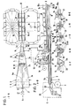
- a metal or plastic strip 2 is pulled off the roll 1 and is guided to the pipe-forming and pipe-filling head 4 via a guide roll 3.
- This head has a molding trough or molding bed 5 and a tube 6 carried therein with a guide section 6a, a molding section 6b and a filling section 6c.
- a filler neck 8 expanded by side channels 9.
- the filler neck 8 is connected to a closed container 11 which contains the insulating material and is integrated in a pressure chamber 12 filled with helium.
- a web 10 is arranged, which covers a certain area to the left and right of a central surface line. The function of this web will be discussed below.
- f üllkopf 4 becomes a tube (2a-d) is formed, wherein the free edges are bent over as a radially outwardly and upwardly projecting flanges 2e Metallblech- or plastic strip.
- Section EF shows shaped bed 5 with a V-shaped strip 2c
- section GH shows a cross section in the area of the filler neck 8, from which the position of the web 10 can also be seen.
- a jaw carousel 16 which consists of two jaw chains which run in an endless loop and which, running between guide rails 17, define a conveying path in which the flanges 2e projecting upwards form one Pipe shaped strip 2 are detected and held frictionally.
- the end 7 of the guiding, shaping and filling tube 6a, b, c extends into the area of the clamping jaws.
- a cover band 18 is unwound from a roller 19 via guide rollers 20 and passed through the tube forming and tube filling head 4 into the preformed tube 2c, d with flange 2e.
- the cover band 18 is placed so that it covers the gap formed by the two flanges 2e upwards. In the area of the filler neck 8, the band is protected and guided by the web 10.
- the cuts JK, LM and NO the location of strip 2 is shown.
- the cable sheath 24 is filled with insulating material 26 via the filler neck and side channels 9 (see section GH and FIG. 2).
- the insulating material now passes through the end 7 of the filling tube 6c into the fully formed cable tube 24 with the flanges 2e (see section LM).
- This process can be adjusted in a metered manner via the vacuum previously existing in the tube 24 on the one hand and the pressure 12 in the insulating material container 11 on the other hand, with evacuation being carried out continuously.
- the cover band 18 is automatically pressed against the slot of the pipe curvature by the flange 2e ; seals this and thus prevents possibly serious contamination from the insulating material 26. Prevention of contamination is particularly important with regard to the subsequent welding of the cable duct jacket.
- the introduction of the insulating material through the filling tube 6c into the cable tube 24 can be supported by an inclined position and a suitable vibration of the guide, molding and filling tube 6a, b, c and thus also the cable tube 24.
- the guide, form and fill tube 6a, b, c can also be in several parts, i. H. consist of several nested pipe sections that can be pulled apart telescopically.
- the fastening plate 14 is arranged vertically adjustable relative to the latter. Analogously, the guide pulley rollers 22 of the cable cores 21 so that they lead centered.
- the masking tape 18 is additionally passed over guide rollers. In this way, all possible combinations are maximally guaranteed and different cable diameters and seamless transitions 58 from one cable diameter to the other can be produced in rapid succession, the density of the insulating material 26 being able to be set the same or different.
- the cable 25 with the flange 2e at the end 28 of the abutment 15a arrives in a guide groove 29 which, with its jaws, holds the cable all around and firmly closed towards the flange 2e.
- a saw blade 30 arranged horizontally above the guide trough cuts off the upstanding flanges 2e, which are wound up via the rollers 31 and 32.
- the now free edges of the tube are welded at 33.
- These stations are shown schematically in Figures 3 and 4, as well as the sections T-U, V-W and X-Y.
- the finished tubular jacket cable 35 leaves the guide trough 29 and is wound up. Instead of the guide trough 29, it is of course also possible to use a further appropriately shaped clamping carousel.
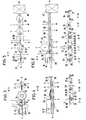
- FIGS. 5 and 6 A further embodiment of the method or a suitable device is shown in FIGS. 5 and 6 with the associated cuts c-d, e-f, g-h, i-k, and I-m.
- the cable 25 with the flange 2e at the end 28 of the abutment also comes into a guide groove 29, as was explained above.
- a wedge 36 then folds the flanges 2e apart and a subsequent rolling wheel 37 presses the flanges completely flat into a plane tangential to the tubular cable. Then this passes through a welding station, the fold edges being welded at 33 and the flange parts 2e thus being connected hermetically sealed to the cable tube jacket.
- the finished tubular jacket cable 38 with the flange 2e leaves the guide trough.
- the flange 2e which greatly facilitates later installation, can still be punched out (shown at 39), making the cable more flexible.
- An annealing process for relaxation is carried out in a downstream station 40, followed by cleaning and
- FIGS. 7 and 8 show a further variant of an apparatus for carrying out the method according to the invention.
- the cable cores 21 run from the pressure vessel 23 via guide pulley rollers 22 into the guide, form and fill tube 6a, b, c, or are drawn into the tube. This passes through, as already described above, the tube forming and tube filling head 4.
- the molding trough or molding bed 5 is not designed as an outer contour, but rather as a channel in which the metal strip unwound from the roll 1 is guided and gradually into a circular shape brought.
- the filler neck 8 opens the insulating material which is fed by the container 11, which in turn is in communication with the pressure chamber 12.
- the insulating material is fed into the interior of the filling tube 6c with the aid of the pressure differences between the pressure chambers 12 and 23 and the vacuum which surrounds the rest of the device and surrounds the cable wires 21 evenly from all sides.
- This station is shown in the section G-H, from which it can be clearly seen how the strip 2d / 24, which is preformed almost to a full circle, surrounds the section 6b of the filling pipe 6c.
- the casing tube is further bent together until the free edges are directly opposite.
- This phase also takes place in the area of the end 7 of the filling tube 6 (see section J-K).
- the free edges are welded at 33 to form a weld seam 34 (see section J-K).
- the end 7 of the filler tube 6 is flattened such that the change in diameter when leaving the filler tube has no adverse effect on the packing density of the insulating material.
- the packing density need not be as high as is required, for example, in the manufacture of tubes with embedded strain gauges, e.g. B. with pure sheathed cables, thermocouples, resistance thermometers, etc.
- transducers such as strain gauges, resistance thermometers, thermocouples and the like
- Combinations of these in one and the same cable jacket tube are also possible.
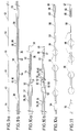
- FIG. 11 shows, for example, a conically widening cable with a totally integrated sensor, the production of which is also possible with the new method.
- an expansion wire 43 is provided with gold-plated areas 44 at predetermined intervals.
- Two equal lengths of wire of the prepared expansion wire are processed to a tubular jacket cable 38 using the manufacturing method described above (FIG. 9b).
- the cable 38 is now cut open at 45 (FIG. 9b) and thus results in the X measuring strips (10a).
- the cable jacket 38 is removed over a certain length (corresponding to the distance between the reference numerals 45 and 46 in FIG. 9b), as a result of which the gold-plated strain gauge wires 44 become visible.
- the insulating material 26 is blown out by means of fine-grained sandblasting, as indicated by arrows.
- the strain gauge 49 thus produced is now connected in a known manner to a cable 35 or 39 in a 3-wire circuit by means of a connecting sleeve 51, the wire ends 21 and 44 are welded together at 59.
- the sleeve 51 is welded on the one hand to the cable 35/39 at 53 and on the other hand to the tube 39/49 of the strain gauge (see Fig. 10b). This creates a strain gauge with an integrated cable, the actual size and appearance of which is shown in FIG. 10c.
- strain gauge 11 shows a strain gauge with a totally integrated cable and a conical transition 58 from the cable 39 to the strain gauge 55/56.
- the strain gauge has integrated fastening flanges 55. The use of the method according to the invention allows the manufacture of such an integrated cable with a transducer in one and the same manufacturing process.
Description
Die Erfindung betrifft ein Verfahren zur Herstellung von elektrischen Kabeln, die einen äußeren Schutzmantel aus Metall sowie einen oder mehrere von Isoliermaterial umgebene elektrische Leiter aufweisen.The invention relates to a method for producing electrical cables which have an outer protective sheath made of metal and one or more electrical conductors surrounded by insulating material.
Kabel mit Metallrohrummantelung enthalten in der Regel einen bis sechs elektrische Leiter, die gegeneinander und bezüglich der Kabelummantelung mittels eines pulverförmigen Materials isoliert sind, welches auch bei höheren Temperaturen ausreichende Isolation bietet. Hierzu wird in den meisten Fällen Magnesiumoxidpulver verwendet, weil sich dieses Material besonders gut für die Herstellung der Kabel eignet. Die üblichen Herstellungsverfahren für derartige Kabel sind die sogenannten «Ziehverfahren», nach denen das Kabel unter Längenzunahme im Querschnitt vermindert wird, wobei das pulverförmige Isoliermaterial komprimiert wird.Cables with a metal tube sheath usually contain one to six electrical conductors which are insulated from one another and with respect to the cable sheath by means of a powdery material which also provides adequate insulation at higher temperatures. Magnesium oxide powder is used in most cases because this material is particularly suitable for the production of cables. The usual manufacturing processes for such cables are the so-called “pulling processes”, according to which the cable is reduced in cross-section with an increase in length, the powdery insulating material being compressed.
Aus der GB-A-687 088 ist ein Verfahren bekannt, bei dem der Metallstreifen in seiner Längsrichtung kontinuierlich durch eine Form gezogen wird, welche bewirkt, daß der Streifen in zunehmendem Maße in Querrichtung gebogen wird. Zwischen den sich in Längsrichtung des gebogenen Streifens erstreckenden Längskanten wird aus einem Trichter das pulverförmige lsoliermaterial eingegeben. Zum Komprimieren des Isoliermaterials ist vor der Materialaufgabestelle eine mit dem fertigen Rohr fluchtende Stampfstange angeordnet, durch deren hohle Achse ein elektrischer Leiter in den gebogenen und mit Isoliermaterial beschickten Mantel eingeführt wird. Die Stampfstange wird hin- und herbewegt, so daß das lsoliermaterialpulver festgestampft wird. Im Anschluß an diesen Vorgang wird das so entstandene Kabel durch eine Ziehform gezogen, so daß der Durchmesser des Kabels verringert wird.From GB-A-687 088 a method is known in which the metal strip is continuously drawn in its longitudinal direction through a shape which causes the strip to be increasingly bent in the transverse direction. The powdery insulating material is introduced from a funnel between the longitudinal edges extending in the longitudinal direction of the bent strip. To compress the insulating material, a ramming rod aligned with the finished tube is arranged in front of the material feed point, through the hollow axis of which an electrical conductor is inserted into the bent jacket and loaded with insulating material. The ramming rod is moved back and forth so that the insulating material powder is rammed. Following this process, the resulting cable is pulled through a drawing die so that the diameter of the cable is reduced.
Dieses bekannte Verfahren ist insofern nachteilig, als eine Stampfstange eine gleichmäßige Komprimierung des lsollermaterialpulvers nicht immer gewährleistet. Bei dem anschließenden Durchziehen des Rohres durch eine Ziehform zwecks Querschnittsverengung des Kabels wird das Isoliermaterialpulver Kräften ausgesetzt, die in Längsrichtung des Rohres wirken. Diese Kräfte tragen zur Komprimierung des Pulvers praktisch nicht bei. Das Isoliermaterialpulver wird zwar abschnittsweise komprimiert, jedoch wird das Pulver durch die Längskräfte aufgelockert, so daß die lsoliermaterialschicht keine gleichmäßige Festigkeit in Längsrichtung des Kabels besitzt. Bei dem Hindurchziehen des Metallstreifens durch die Ziehform wird der Streifen sehr stark plastisch verformt. Die zur dieser Verformung . aufzubringenden Kräfte sind beträchtlich. Material und Dicke des Metallstreifens müssen folglich so gewählt werden, daß eine Beschädigung des Mantels durch die hohen Ziehkräfte nicht zu befürchten ist.This known method is disadvantageous in that a tamping rod does not always ensure uniform compression of the powder material. When the tube is then pulled through a drawing mold to narrow the cross section of the cable, the insulating material powder is subjected to forces which act in the longitudinal direction of the tube. These forces practically do not contribute to the compression of the powder. The insulating material powder is compressed in sections, but the powder is loosened by the longitudinal forces, so that the insulating material layer does not have a uniform strength in the longitudinal direction of the cable. When the metal strip is pulled through the drawing mold, the strip is deformed very strongly plastically. The one for this deformation. The forces to be exerted are considerable. Material and thickness of the metal strip must therefore be chosen so that there is no fear of damage to the jacket due to the high drawing forces.
Aus der FR-A-848 495 ist in Übereinstimmung mit dem Oberbegriff des Anspruchs 1 ein Verfahren bekannt, bei dem das Rohr durch einzelne Ziehblöcke geleitet 'wird, deren Ziehöffnungsquerschnitte sich von Block zu Block verkleinern. Hierbei wird in einer Ausführungsform erreicht, daß die Längskanten des Metallstreifens sich in der zu einem Rohr gebogenen Form teilweise überlappen, wobei das Ausmaß der Überlappung umsomehr zunimmt, desto weiter der betreffende Mantelrohrabschnitt durch die Ziehvorrichtung hindurchgezogen ist. In einer speziellen Ausführungsform dieses bekannten Verfahrens ist die Breite des Metallstreifens derart auf den Endquerschnitt des Mantelrohres abgestimmt, daß die beiden Kanten des Metallstreifens im Endzustand des Mantelrohres stumpf gegeneinanderstossen. Die Schwierigkeit bei diesem bekannten Verfahren besteht einmal darin, daß sich die Kanten des Metallstreifens in erheblichem Maße überlappen, so daß das Mantelrohr an einigen Stellen relativ dick ist. Insgesamt ergibt siche eine unregelmäßige Dicke des Mantelrohres. Ist der Metallstreifen für das Mantelrohr so gewählt, daß die beiden Längskanten des Streifens stumpf gegeneinanderstossen, wenn das Rohr seine endgültige Dicke hat, so müssen die Abmessungen von Ziehblockquerschnitt einerseits und Metallstreifen andererseits sehr fein aufeinander abgestimmt sein. Dieses bekannte Verfahren hat mit dem oben erläuterten bekannten Verfahren gemäß der GB-A-687 088 den Nachteil gemeinsam, daß der Mantel sehr hohen Ziehkräften ausgesetzt ist, so daß Beschädigungen des Mantels zu befüchten sind.From FR-A-848 495, in accordance with the preamble of
Ein ähnliches Verfahren ist aus der FR-A-840 026 bekannt. Auch bei diesem bekannten Verfahren werden die zur Querschnittsverengung des Kabels und mithin zur Komprimierung des Isoliermaterialpulvers benötigten Kräfte durch eine das Kabel in Längsrichtung ziehende Ziehvorrichtung aufgebracht. Hierdurch ergeben sich die gleichen Nachteile, wie sie für die oben erläuterten bekannten Verfahren angegeben wurden.A similar process is known from FR-A-840 026. In this known method, too, the forces required for narrowing the cross-section of the cable and consequently for compressing the insulating material powder are applied by a pulling device which pulls the cable in the longitudinal direction. This results in the same disadvantages as were given for the known methods explained above.
Der Erfindung liegt die Aufgabe zugrunde, ein Verfahren der im Oberbegriff des Anspruchs 1 angegebenen Art derart weiterzubilden, daß das pulverförmige Isoliermaterial in einer Weise komprimiert wird, daß es im fertigen Zustand des Kabels an allen Stellen gleichmäßig stark komprimiert ist. Außerdem soll das Verfahren gewährleisten, daß der Mantel beim Komprimieren des Isoliermaterials nicht übermäßig stark beansprucht wird.The invention has for its object to develop a method of the type specified in the preamble of
In Übereinstimmung mit dem kennzeichnenden Teil des Anspruchs 1 wird diese Aufgabe dadurch gelöst, daß zur Durchmesserreduzierung und gleichzeitiger Komprimierung des Isoliermaterials mit den Leitern das entstandene Rohr an den Flanschen reibschlüssig gefaßt und gegen ein Widerlager gezogen wird, daß die abstehenden Flansche gegebenenfalls, nachdem sie auseinandergebogen wurden, zumindest teilweise abgetrennt werden und daß die inneren, aneinergepreßten Kanten vor oder nach dem Abtrennvorgang verschweißt werden.In accordance with the characterizing part of
Der Grundgedanke der Erfindung liegt darin, das Komprimieren des Isolierpulvers dadurch zu bewerkstelligen, daß die Radialflansche in radialer Richtung gezogen werden, während das bis dahin entstandene Rohr gegen ein Widerlager gezogen wird. Durch diese Maßnahme wird erreicht, daß sich der Querschnitt des Rohres verkleinert und das Isoliermaterial dementsprechend komprimiert wird. Die hierbei auf den Mantel einwirkenden Kräfte sind weniger groß als bei den oben erläuterten Längs-Ziehverfahren, bei denen eine starke plastische Verformung unter Verringerung der Wandstärke des Metallmantels erfolgt. Bei dem erfindungsgemäßen Verfahren wird der Metallmantel hauptsächlich stärker gebogen. Da das Kabel praktisch keiner Längsverformung unterworfen wird, bleiben auch die Kabeiadern beschädigungsfrei.The basic idea of the invention is to accomplish the compression of the insulating powder by pulling the radial flanges in the radial direction, while pulling the tube which has been formed up to that point against an abutment. This measure ensures that the cross section of the tube is reduced and the insulating material is compressed accordingly. The forces acting on the jacket are less than in the case of the longitudinal drawing processes explained above, in which there is a strong plastic deformation while reducing the wall thickness of the metal jacket. In the method according to the invention, the metal jacket is mainly bent more. Since the cable is practically not subjected to any longitudinal deformation, the wire strands also remain undamaged.
Vorteilhafte Weiterbildungen der Erfindung sind in den Unteransprüchen angegeben. Speziell betrifft der Anspruch 4 eine Vorrichtung zur Durchführung des erfindungsgemäßen Verfahrens.Advantageous developments of the invention are specified in the subclaims. Specifically,
Mit dem Verfahren bzw. der Vorrichtung nach der Erfindung können, abgesehen von normalen ummantelten Kabeln, auch Hochtemperatur-Dehnungsmeßstreifen, Temperaturmeßfühler und dergleichen hergestellt werden. Zur gleichzeitigen Erfassung von Dehnungen und Temperaturen können in den Kabeln auch Dehnungsmeßstreifen mit Temperaturfühlern auf Thermoelement- oder Widerstandsbasis kombiniert werden. Die Temperaturfühler können dabei noch zur Kompensation des Fehlers aus der scheinbaren Dehnung herangezogen werden.With the method and the device according to the invention, apart from normal sheathed cables, high-temperature strain gauges, temperature sensors and the like can also be produced. Strain gauges can also be combined in the cables with temperature sensors based on thermocouples or resistance to simultaneously record strains and temperatures. The temperature sensors can also be used to compensate for the error from the apparent expansion.
Nachfolgend werden Ausführungsformen der Erfindung anhand der beigefügten Zeichnung beispielsweise bebeschrieben. Darin zeigen :
- Figur. 1 die schematische Draufsicht auf eine Vorrichtung zur Durchführung des Verfahrens,
Figur 2 einen schematischen Längsschnitt durch die Vorrichtung, sowie Querschnitte an fünf verschiedenen Stellen der Längsachse der Vorrichtung,Figur 3 eine schematische Draufsicht auf die im Fertigungsablauf letzten Stationen der Vorrichtung gemäß denFiguren 1 und 2,Figur 4 einen Längsschnitt durch den Vorrichtungsteil der Fig. 3 mit Querschnitten and drei verschiedenen Stellen der Längsachse,Figur 5 eine Draufsicht auf die letzten Stationen im Fertigungsablauf einer Vorrichtung in modifizierter Ausführung,- Figur 6 einen schematischen Längsschnitt durch den Vorrichtungsteil gemäß Fig. 5 und Querschnitte an fünf verschiedenen Stellen der Längsachse der Vorrichtung,
Figur 7 eine schematische Draufsicht auf eine weitere Ausführungsform der Vorrichtung,Figur 8 einen schematischen Längsschnitt durch die Vorrichtung gemäb Fig. 7 mit Querschnitten an vier verschiedenen Stellen der Längsachse der Vorrichtung,- Figur 9a und b zeigen Zwischenstadien eines ummantelten Kabels zur Erzeugung von Meßwertwandlern,
- Figur 10a, b, c zeigen die Verbindung des Meßwertwandlers gemäß den Fig. 9a und b mit einem ummantelten Kabel, das gemäß einer Modifikation des erfindungsgemäßen Verfahrens hergestellt wurde,
Figur 11 zeigt ein ummanteltes Kabel mit total integriertem Dehnungsstreifen und sich allmählich zum Dehnungsmeßstreifen hin verjüngendem Durchmesser.
- Figure. 1 shows the schematic top view of an apparatus for carrying out the method,
- FIG. 2 shows a schematic longitudinal section through the device, as well as cross sections at five different points on the longitudinal axis of the device,
- FIG. 3 shows a schematic plan view of the last stations of the device according to FIGS. 1 and 2 in the production sequence,
- FIG. 4 shows a longitudinal section through the device part of FIG. 3 with cross sections at three different locations on the longitudinal axis,
- FIG. 5 shows a plan view of the last stations in the production sequence of a device in a modified version,
- FIG. 6 shows a schematic longitudinal section through the device part according to FIG. 5 and cross sections at five different locations on the longitudinal axis of the device,
- FIG. 7 shows a schematic top view of a further embodiment of the device,
- FIG. 8 shows a schematic longitudinal section through the device according to FIG. 7 with cross sections at four different points on the longitudinal axis of the device,
- FIGS. 9a and b show intermediate stages of a sheathed cable for producing transducers,
- 10a, b, c show the connection of the transducer according to FIGS. 9a and b with a sheathed cable which was produced according to a modification of the method according to the invention,
- FIG. 11 shows a sheathed cable with a totally integrated strain gauge and a diameter that gradually tapers towards the strain gauge.
Gemäß Fig. 1 wird von der Rolle 1 ein Metall-oder Kunststoffband 2 abgezogen, das über eine Führungsrolle 3 zum Rohrform- und Rohrfüllkopf 4 geleitet wird. Dieser Kopf weist eine Formwanne oder Formbett 5 und ein darin durchgeführtes Rohr 6 mit einem Führungsabschnitt 6a, einem Formabschnitt 6b und einem Füllabschnitt 6c auf. Zwischen dem Bereich des Führungs- und Formabschnittes 6a, b befindet sich ein Füllstutzen 8, erweitert durch Seitenkanäle 9. Der Füllstutzen 8 steht mit einem geschlossenen Behälter 11 in Verbindung, welcher das Isoliermaterial enthält und in eine mit Helium gefüllte Druckkammer 12 integriert ist. Im Bereich des Füllstutzens 8 ist ein Steg 10 angeordnet, der einen bestimmten Bereich links und rechts einer mittleren Mantellinie abdeckt. Auf die Funktion dieses Steges wird nachfolgend noch eingegangen werden.According to FIG. 1, a metal or
Im Rohrform- und Rohrfüllkopf 4 wird ein Metallblech- oder Kunststoffstreifen 2 zu einem Rohr (2a-d) geformt, wobei dessen freie Kanten als radial nach außen bzw. oben abstehende Flansche 2e umgebogen werden. Schnitt E-F zeigt Formbett 5 mit V-förmig herumgebogenem Streifen 2c, Schnitt G-H zeigt einen Querschnitt im Bereich des Füllstutzens 8, aus dem auch die Lage des Steges 10 ersichtlich ist.In the hollow profiles and pipes f üllkopf 4 becomes a tube (2a-d) is formed, wherein the free edges are bent over as a radially outwardly and upwardly projecting
Anschließend an den Rohrform- und Rohrfüllkopf 4 ist ein Klemmbacken-Karussel 16 angeordnet, das aus zwei in endloser Schleife geführten Klemmbacken-Ketten besteht, die, zwischen Führungsschienen 17 laufend, eine Förderstrecke definieren, in welcher die nach oben ragenden Flansche 2e des zu einem Rohr geformten Streifens 2 erfaßt und reibschlüssig gehalten werden.Subsequent to the tube forming and
Das Ende 7 des Führungs-, Form- und Füllrohres 6a, b, c, reicht bis in den Bereich der Klemmbacken hinein. Gleichlaufend mit der beschriebene Verformung des Streifens zu einem Rohr wird ein Abdeckband 18 von einer Rolle 19 über Führungsrollen 20 abgespult und durch den Rohrform- und Rohrfüllkopf 4 hindurch in das vorgeformte Rohr 2c, d mit Flansch 2e geleitet. Dabei wird das Abdeckband 18 so plaziert, daß es nach oben hin den durch die beiden Flansche 2e gebildeten Spalt abdeckt. Im Bereich des Füllstutzens 8 wird das Band durch den Steg 10 geschützt und geführt. In den Schnitten J-K, L-M und N-O ist die Lage des Streifens 2 gezeigt.The
Synchron hierzu erfolgt das Einfädeln der Kabeladern 21 über die Führungsscheibenrollen 22. Aus der Druckkammer 23 heraus gelangen diese durch das abgeschlossene Führungs-, Form- und Füllrohr 6a, b, c, in das vorgeformteKabelrohr 2c, d, e.Synchronously with this, the threading of the
Die Füllung des Kabelmantels 24 mit Isoliermaterial 26 erfolgt über den Füllstutzen und Seitenkanäle 9 (siehe Schnitt G-H und Fig. 2). Das Isoliermaterial gelangt nun über das Ende 7 des Füllrohres 6c in das fertig geformte Kabelrohr 24 mit den Flanschen 2e (siehe Schnitt L-M). Dieser Vorgang ist dosiert einstellbar über das zuvor im Rohr 24 existierende Vakuum einerseits und den Druck 12 im Isoliermaterialbehälter 11 andererseits, wobei kontinuierlich evakuiert wird. Hierbei wird das Abdeckband 18 automatisch an den Schlitz der Rohrwölbung vom Flansch 2e gepresst; dichtet diesen ab und verhindert damit eine unter Umständen folgenschwere Verschmutzung durch das Isoliermaterial 26. Besonders im Hinblick auf die spätere Verschweißung des Kabelrohrmantels ist eine Verhinderung der Verschmutzung von Wichtigkeit. Die Einführung des lsoliermaterials durch das Füllrohr 6c in das Kabelrohr 24 kann durch Schräglage und eine geeignete Vibration des Führungs-, Form-und Füllrohres 6a, b, c und damit auch des Kabelrohres 24 unterstützt werden.The
Zum Zwecke einer möglichst hohen Kompression des Isoliermaterials 26 im Kabelrohr 24 wird dieses an seinem Flansch 2e von entgegenläufigen Klemmbacken 16 des Klemmbacken-Karussels erfaßt, wobei die Klemmbacken zwischen den Führungsschienen 17 laufen und die Flansche 2e festklemmen. Das Kabelrohr 24 legt sich dabei an das Widerlager 15a an (siehe Schnitt L-M). Die Klemmbacken 16 laufen auf dem Widerlager 15a entlang, wobei der eingeklemmte Flansch 2e von den Klemmbacken 16 nach oben gezogen wird. Durch die langsam ansteigende Schräge 27 des Widerlagers wird der Flansch 2e nach obengezogen und das Kabelrohr 24 entsprechend verjüngt bzw. dessen Durchmesser verringert (siehe Schnitt N-O). Dadurch, daß die Steigung 27 des Widerlagers kontinuierlich verstellbar ist, d. h. während des Fertigungsablaufes geändert werden kann, kann der Mantel des Kabelrohrs 24 eine konische Verbreiterung bzw. Verjüngung erfahren, wobei gleichzeitig die Füllungen des Kabelrohrs 24 mit Isoliermaterial 26 entsprechend dosiert und dem unterschiedlichen Durchmesser angepaßt werden kann. Um dabei größere Kabeldurchmesserdifferenzen zu überwinden, kann das Führungs-, Form- und Füllrohr 6a, b, c auch mehrteilig sein, d. h. aus mehreren ineinander geschachtelten Rohrschüssen bestehen, die teleskopartig auseinandergezogen werden können. Um den sich damit ändernden radialen Abstand des Form- und Füllrohres 6b, c gegenüber dem Widerlager 15a zu kompensieren, wird die Befestigungsplatte 14 gegenüber letzterem senkrecht verstellbar angeordnet. Analog dazu die Führungsscheibenrollen 22 der Kabeladern 21, damit diese zentriert bleiden. Desgleichen wird das Abdeckband 18 zusätzlich über Führungsrollen geleitet. Damit werden alle Kombinationsmöglichkeiten maximal gewährleistet und es können in rascher Folge unterschiedliche Kabeldurchmesser sowie nahtlose Übergänge 58 von einem Kabeldurchmesser auf den anderen gefertigt werden, wobei die Dichte des Isoliermaterials 26 gleich oder auch unterschiedlich eingestellt werden kann.For the purpose of the highest possible compression of the insulating
Nach dem Verlassen des Klemmbacken-Karussels 16 gelangt das Kabel 25 mit dem Flansch 2e am Ende 28 des Widerlagers 15a in eine Führungsrinne 29, welche mit ihren Backen das Kabel rundherum und zum Flansch 2e hin fest geschlossen hält. Ein waagrecht über der Führungsrinne angeordnetes Sägeblatt 30 schneidet die nach oben ragenden Flansche 2e ab, die über die Rollen 31 und 32 aufgespult werden. Die nunmehr freien Kanten des Rohres werden bei 33 verschweißt. Diese Stationen sind in den Figuren 3 und 4, sowie den Schnitten T-U, V-W und X-Y schematisch dargestellt. Das fertige Rohrmantelkabel 35 verläßt die Führungsrinne 29 und wird aufgespult. Statt der Führungsrinne 29 kann natürlich auch ein weiteres entsprechend ausgeformtes Klemmbacken-Karussel angewendet werden.After leaving the clamping
Eine weitere Ausführungsform des Verfahrens bzw. einer geeigneten Vorrichtung ist in den Figuren 5 und 6 mit den zugeordneten Schnitten c-d, e-f, g-h, i-k, und I-m dargestellt. Dabei gelangt das Kabel 25 mit dem Flansch 2e am Ende 28 des Widerlagers ebenfalls in eine Führungsrinne 29, wie dies zuvor erklärt wurde. Dann klappt ein Keil 36 die Flansche 2e auseinander und ein nachfolgendes Walzrad 37 drückt die Flansche vollends flach in eine zum Rohrkabel tangentiale Ebene. Dann durchläuft dieses eine Schweißstation, wobei bei 33 die Falzkanten verschweißt und damit die Flanschteile 2e hermetisch dicht mit dem Kabelrohrmantel verbunden werden. Das fertige Rohrmantelkabel 38 mit dem Flansch 2e verläßt die Führungsrinne. Der Flansch 2e, der eine spätere Installation wesentlich erleichtert, kann noch ausgestanzt werden (bei 39 gezeigt), wodurch das Kabel flexiber wird. In einer nachgeschalteten Station 40 wird ein Glühprozeß zur Entspannung durchgeführt, mit anschließender Reinigung und Prüfung des Kabels.A further embodiment of the method or a suitable device is shown in FIGS. 5 and 6 with the associated cuts c-d, e-f, g-h, i-k, and I-m. The
.. In den Figuren 7 und 8 ist eine weitere Variante einer Vorrichtung zur Durchführung des erfindungsgemäßen Verfahrens dargestellt.. . FIGS. 7 and 8 show a further variant of an apparatus for carrying out the method according to the invention.
Die Kabeladern 21 laufen aus dem Druckbehälter 23 über Führungsscheibenrollen 22 in das Führungs-, Form- und Füllrohr 6a, b, c ein, bzw. werden in das Rohr eingezogen. Dieses durchsetzt wie bereits vorstehend beschrieben, den Rohrform- und Rohrfüllkopf 4. Allerdings ist in diesem Fall die Formwanne bzw. Formbett 5 nicht als Außenkontur, sondern als Rinne ausgebildet, in der der von der Rolle 1 abgespulte Metallstreifen zwangsgeführt und allmählich in eine kreisrunde Form gebracht wird. Im Bereich 6b des Füllrohres mündet der Einfüllstutzen 8 für das Isoliermaterial, der vom Behälter 11 gespeist wird, welcher wiederum mit der Druckkammer 12 in Verbindung steht.The
Das Isoliermaterial wird mit Unterstützung der Druckunterschiede zwischen den Druckkammern 12 und 23 und dem Vakuum, welches die übrige Vorrichtung umgibt, in das Innere des Füllrohres 6c eingespeist und umgibt die Kabeladern 21 gleichmäßig von allen Seiten. Diese Station ist in dem Schnitt G-H dargestellt, aus dem gut ersichtlich ist, wie der fast zu einem Vollkreis vorgeformte Streifen 2d/24 den Abschnitt 6b des Füllrohres 6c umgibt.The insulating material is fed into the interior of the filling
Im weiteren Verlauf wird das Mantelrohr weiter rohrförmig zusammengebogen, bis sich die freien Kanten unmittelbar gegenüberstehen. Auch diese Phase findet noch im Bereich des Endes 7 des Füllrohres 6 statt (siehe Schnitt J-K). Nun erfolgt eine Verschweißung der freien Kanten bei 33 unter Bildung einer Schweißnaht 34 (vgl. Schnitt J-K). Erst nach Verschweißung der Längsnaht endet das Füllrohr 6 an der Stelle 7. Vorzugsweise ist das Ende 7 des Füllrohres 6 so angeflacht, daß der Durchmessersprung beim Verlassen des Füllrohres keinen ungünstigen Einfluß auf die Packungsdichte des Isoliermaterials hat. Es gibt andererseits eine Reihe von Anwendungsfällen, bei denen die Packungsdichte nicht so hoch sein muß, wie es beispielsweise bei der Fertigung von Röhrchen mit eingelagerten Dehnungsmeßdrähten erforderlich ist, so z. B. bei reinen Mantelkabeln, Thermoelementen, Widerstandsthermometern usw. Als Variante dieses Verfahrens ist es auch möglich, den Streifen spiralig zusammenzudrehen bzw. zu schieben und noch im Bereich des Füllrohres zu verschweißen.In the further course, the casing tube is further bent together until the free edges are directly opposite. This phase also takes place in the area of the
Mit dem erfindungsgemäßen Verfahren lassen sich ohne Änderungen der Vorrichtung auch Meßwertwandler, wie zum Beispiel Dehnungsmeßstreifen, Widerstandsthermometer, Thermoelemente u. a. m. herstellen. Auch Kombinationen davon in ein- und demselben Kabelmantelrohr (siehe Figuren 9 und 10) sind möglich. Figur 11 zeigt beispielsweise ein sich konisch erweiterndes Kabel mit total integriertem Meßfühler, dessen Herstellung mit dem neuen Verfahren ebenfalls möglich ist.With the method according to the invention, transducers, such as strain gauges, resistance thermometers, thermocouples and the like, can be changed without changing the device. a. m. produce. Combinations of these in one and the same cable jacket tube (see FIGS. 9 and 10) are also possible. FIG. 11 shows, for example, a conically widening cable with a totally integrated sensor, the production of which is also possible with the new method.
Nachfolgend soll die Herstellung eines Dehnungsmeßstreifens beschrieben werden. Zunächst wird gemäß Fig. 9a ein Dehnungsdraht 43 in vorgegebenen Abständen mit vergoldeten Bereichen 44 versehen. Zwei gleiche Drahtlängen des vorbereiteten Dehnungsdrahtes werden unter Anwendung des zuvor beschriebenen Fertigungsverfahrens zu einem Rohrmantelkabel 38 verarbeitet (Fig. 9b). Das Kabel 38 wird nun bei 45 (Fig. 9b) aufgeschnitten und ergibt somit die X-Meßstreifen (10a). Jetzt wird der Kabelmantel 38 über eine bestimmte Länge entfernt (entsprechend der Distanz zwischen den Bezugsziffern 45 und 46 in Fig. 9b), wodurch die vergoldeten Dehnungsmeßstreifendrähte 44 sichtbar werden. Am anderen Ende wird das Isoliermaterial 26 mittels feinstkörniger Sandstrahlung herausgeblasen, wie dies durch Pfeile angedeutet ist. Damit werden die beiden Dehnungsdrähte 43 bloßgelegt, die mittels einer Kondensatorentladung miteinander zu einer Schlaufe verschweißt werden. Die überstehenden Enden werden abgeschnitten und das Röhrchen mit einem Siegelpfropfen 47 verschlossen. Der Rest des Rohrmantels wird zur Hälfte mit dem Isoliermaterial 26 aufgefüllt und durch eine Quetschschweißung 48 verschlossen. Der so gefertigte Dehnungsmeßstreifen 49 wird nun in bekannter Weise mit einem Kabel 35 oder 39 in 3-Leiterschaltung mittels einer Verbindungsmuffe 51 verbunden, die Drahtenden 21 und 44 werden bei 59 miteinander verschweißt. Die Muffe 51 wird einerseits mit dem Kabel 35/39 bei 53 und andererseits mit dem Rohr 39/49 des Dehnungsmeßstreifens verschweißt (siehe Fig. 10b). Damit ist ein Dehnungsmeßstreifen mit integriertem Kabel geschaffen, dessen tatsächliche Größe und Aussehen Fig. 10c wiedergibt.The production of a strain gauge will be described below. First, according to FIG. 9 a, an
In Fig. 11 ist ein Dehnungsmeßstreifen mit total integriertem Kabel und konischem Übergang 58 vom Kabel 39 zum Dehnungsmeßstreifen 55/56 abgebiltet. Der Dehnungsmeßstreifen weist gemäß einer zuvor beschriebenen Verfahrensvariante integrierte Befestigungsflansche 55 auf. Die Anwendung des erfindungsgemäßen Verfahrens erlaubt die Fertigung eines solchen integrierten Kabels mit Meßwertwandler in ein und demselben Fertigungsgang.11 shows a strain gauge with a totally integrated cable and a
Claims (4)
Applications Claiming Priority (2)
| Application Number | Priority Date | Filing Date | Title |
|---|---|---|---|
| DE3109101A DE3109101C2 (en) | 1981-03-10 | 1981-03-10 | Process for the manufacture of electrical cables |
| DE3109101 | 1981-03-10 |
Publications (3)
| Publication Number | Publication Date |
|---|---|
| EP0059971A2 EP0059971A2 (en) | 1982-09-15 |
| EP0059971A3 EP0059971A3 (en) | 1983-01-19 |
| EP0059971B1 true EP0059971B1 (en) | 1985-08-28 |
Family
ID=6126829
Family Applications (1)
| Application Number | Title | Priority Date | Filing Date |
|---|---|---|---|
| EP82101838A Expired EP0059971B1 (en) | 1981-03-10 | 1982-03-08 | Manufacturing method of sheathed cables, as well as a device for carrying out the method |
Country Status (4)
| Country | Link |
|---|---|
| US (1) | US4437914A (en) |
| EP (1) | EP0059971B1 (en) |
| JP (1) | JPS57210518A (en) |
| DE (1) | DE3109101C2 (en) |
Families Citing this family (10)
| Publication number | Priority date | Publication date | Assignee | Title |
|---|---|---|---|---|
| CA2010785A1 (en) * | 1989-02-24 | 1990-08-24 | Ronald A. Simester | Mineral insulated cable manufacture |
| GB9008258D0 (en) * | 1990-04-11 | 1990-06-13 | Bicc Plc | Mineral insulated cable manufacture |
| US5121872A (en) * | 1991-08-30 | 1992-06-16 | Hydrolex, Inc. | Method and apparatus for installing electrical logging cable inside coiled tubing |
| US5479690A (en) * | 1993-12-01 | 1996-01-02 | Hoskins Manufacturing Company | Tube making mechanism having a fill tube for depositing a ceramic powder into the tube as it is being made |
| WO1995018777A1 (en) * | 1994-01-05 | 1995-07-13 | Roth-Technik Gmbh & Co. Forschung Für Automobil- Und Umwelttechnik | Electrically conductive connection |
| JP2003001323A (en) * | 2001-06-13 | 2003-01-07 | Mitsubishi Shindoh Co Ltd | Squeeze roll unit device for electric resistance welded pipe |
| NO20101268A1 (en) * | 2010-09-10 | 2012-03-12 | Inst Energiteknik | Cable Pull Voltage Sensor |
| DE102016111738A1 (en) * | 2016-06-27 | 2017-12-28 | Heraeus Sensor Technology Gmbh | Cable for contacting a sensor, temperature measuring device, method for connecting a cable to a temperature measuring device and use of an alloy for producing a cable |
| CN113450975B (en) * | 2021-06-16 | 2022-09-27 | 安徽正豪电缆有限公司 | Wear-resistant and corrosion-resistant sheath for cable and coating device thereof |
| CN114360811B (en) * | 2021-11-23 | 2024-03-08 | 浙江元通线缆制造有限公司 | Production process for continuously producing rigid mineral cables |
Family Cites Families (7)
| Publication number | Priority date | Publication date | Assignee | Title |
|---|---|---|---|---|
| FR840026A (en) * | 1937-12-18 | 1939-04-18 | Method and device for the manufacture of cables or shielded conductors with incombustible mineral insulation | |
| DE738591C (en) * | 1938-12-16 | 1943-08-21 | Karl Fischer | Method and device for the production of electrical tubular heating elements |
| FR848495A (en) * | 1939-01-05 | 1939-10-31 | Geoffroy Delore | Method and device for the manufacture of compressed insulation cables |
| US2253069A (en) * | 1939-05-20 | 1941-08-19 | Western Electric Co | Core covering apparatus |
| GB687088A (en) * | 1950-11-14 | 1953-02-04 | Glover & Co Ltd W T | Improvements in the manufacture of insulated electric conductors |
| US3530019A (en) * | 1968-05-28 | 1970-09-22 | Gen Cable Corp | Apparatus and method for making laminated cable sheath |
| GB1554859A (en) * | 1975-11-06 | 1979-10-31 | Bicc Ltd | Manufacture of mineral insulated electric cables |
-
1981
- 1981-03-10 DE DE3109101A patent/DE3109101C2/en not_active Expired
-
1982
- 1982-03-08 US US06/355,455 patent/US4437914A/en not_active Expired - Fee Related
- 1982-03-08 EP EP82101838A patent/EP0059971B1/en not_active Expired
- 1982-03-10 JP JP57037891A patent/JPS57210518A/en active Pending
Also Published As
| Publication number | Publication date |
|---|---|
| DE3109101C2 (en) | 1984-02-23 |
| US4437914A (en) | 1984-03-20 |
| EP0059971A2 (en) | 1982-09-15 |
| DE3109101A1 (en) | 1982-09-23 |
| EP0059971A3 (en) | 1983-01-19 |
| JPS57210518A (en) | 1982-12-24 |
Similar Documents
| Publication | Publication Date | Title |
|---|---|---|
| DE4019899C1 (en) | ||
| DE2746929C2 (en) | Device for forming a corrugated metallic screen with an unconnected seam line on a cable core | |
| EP0059971B1 (en) | Manufacturing method of sheathed cables, as well as a device for carrying out the method | |
| DE3004357C2 (en) | ||
| EP3804048B1 (en) | Device and method for processing an end of an electrical cable | |
| DE2360481C3 (en) | Hollow rod closed on one side made of a shirred tubular casing with an end closure formed from unfolded tubular casing and a method for producing the closure located in the rod cavity | |
| DE1960932A1 (en) | Process for the production of heat and sound insulated line pipes | |
| DE3004387C2 (en) | ||
| DE1239380B (en) | Method for manufacturing a high-frequency submarine cable | |
| AT407545B (en) | TENSION BUNDLE AND METHOD AND DEVICE FOR PRODUCING THE SAME | |
| EP2243567B1 (en) | Device for producing pipes corrugated at right angles to their cross-section | |
| DE3204887C2 (en) | ||
| EP1103013A1 (en) | Method of producing an optical cable with an excessive length of the optical waveguides | |
| EP0210411B1 (en) | Manufacturing method of a metallic jacket for an electric cable externally having an angular and internally a rounded outline | |
| DE1415815B2 (en) | Process for the production of spacers for airspace-insulated coaxial cables | |
| CH368840A (en) | Method and device for sheathing a cable with a metal jacket | |
| DE19818733B4 (en) | Method for producing a composite pipe and composite pipe | |
| DE738591C (en) | Method and device for the production of electrical tubular heating elements | |
| DE2829517C2 (en) | Filled welding wire and process for its manufacture | |
| DE3034427A1 (en) | METHOD FOR PRODUCING MINERALLY INSULATED ELECTRIC CABLES | |
| DE738627C (en) | Process for the production of electric tubular heating elements | |
| DE1907107C3 (en) | Process for the production of copper-clad aluminum wires | |
| DE2112462C3 (en) | Method and apparatus for producing a rope or the like consisting of several wires | |
| DE3044004A1 (en) | Longitudinally welded small calibre syringe needles tube mfr. - comprises shaping metal strip into slot tube, with subsequent electronic welding | |
| DE19729016C1 (en) | Method of processing stranded ends of cables |
Legal Events
| Date | Code | Title | Description |
|---|---|---|---|
| PUAI | Public reference made under article 153(3) epc to a published international application that has entered the european phase |
Free format text: ORIGINAL CODE: 0009012 |
|
| AK | Designated contracting states |
Designated state(s): BE CH FR GB IT LU NL SE |
|
| PUAL | Search report despatched |
Free format text: ORIGINAL CODE: 0009013 |
|
| AK | Designated contracting states |
Designated state(s): BE CH FR GB IT LI LU NL SE |
|
| 17P | Request for examination filed |
Effective date: 19830630 |
|
| ITF | It: translation for a ep patent filed |
Owner name: JACOBACCI & PERANI S.P.A. |
|
| GRAA | (expected) grant |
Free format text: ORIGINAL CODE: 0009210 |
|
| AK | Designated contracting states |
Designated state(s): BE CH FR GB IT LI LU NL SE |
|
| PG25 | Lapsed in a contracting state [announced via postgrant information from national office to epo] |
Ref country code: NL Effective date: 19850828 Ref country code: BE Effective date: 19850828 |
|
| PG25 | Lapsed in a contracting state [announced via postgrant information from national office to epo] |
Ref country code: SE Effective date: 19850830 |
|
| ET | Fr: translation filed | ||
| NLV1 | Nl: lapsed or annulled due to failure to fulfill the requirements of art. 29p and 29m of the patents act | ||
| PG25 | Lapsed in a contracting state [announced via postgrant information from national office to epo] |
Ref country code: LU Free format text: LAPSE BECAUSE OF NON-PAYMENT OF DUE FEES Effective date: 19860331 |
|
| PLBE | No opposition filed within time limit |
Free format text: ORIGINAL CODE: 0009261 |
|
| STAA | Information on the status of an ep patent application or granted ep patent |
Free format text: STATUS: NO OPPOSITION FILED WITHIN TIME LIMIT |
|
| 26N | No opposition filed | ||
| ITTA | It: last paid annual fee | ||
| PGFP | Annual fee paid to national office [announced via postgrant information from national office to epo] |
Ref country code: GB Payment date: 19920826 Year of fee payment: 11 |
|
| PGFP | Annual fee paid to national office [announced via postgrant information from national office to epo] |
Ref country code: FR Payment date: 19920916 Year of fee payment: 11 |
|
| PGFP | Annual fee paid to national office [announced via postgrant information from national office to epo] |
Ref country code: CH Payment date: 19920918 Year of fee payment: 11 |
|
| PG25 | Lapsed in a contracting state [announced via postgrant information from national office to epo] |
Ref country code: GB Effective date: 19930308 |
|
| PG25 | Lapsed in a contracting state [announced via postgrant information from national office to epo] |
Ref country code: CH Effective date: 19930331 Ref country code: LI Effective date: 19930331 |
|
| GBPC | Gb: european patent ceased through non-payment of renewal fee |
Effective date: 19930308 |
|
| PG25 | Lapsed in a contracting state [announced via postgrant information from national office to epo] |
Ref country code: FR Effective date: 19931130 |
|
| REG | Reference to a national code |
Ref country code: CH Ref legal event code: PL |
|
| REG | Reference to a national code |
Ref country code: FR Ref legal event code: ST |