EP0059573A1 - Mould opening and closing mechanism - Google Patents
Mould opening and closing mechanism Download PDFInfo
- Publication number
- EP0059573A1 EP0059573A1 EP82300874A EP82300874A EP0059573A1 EP 0059573 A1 EP0059573 A1 EP 0059573A1 EP 82300874 A EP82300874 A EP 82300874A EP 82300874 A EP82300874 A EP 82300874A EP 0059573 A1 EP0059573 A1 EP 0059573A1
- Authority
- EP
- European Patent Office
- Prior art keywords
- mould
- support
- portions
- levers
- link
- Prior art date
- Legal status (The legal status is an assumption and is not a legal conclusion. Google has not performed a legal analysis and makes no representation as to the accuracy of the status listed.)
- Granted
Links
Images


Classifications
-
- C—CHEMISTRY; METALLURGY
- C03—GLASS; MINERAL OR SLAG WOOL
- C03B—MANUFACTURE, SHAPING, OR SUPPLEMENTARY PROCESSES
- C03B9/00—Blowing glass; Production of hollow glass articles
- C03B9/30—Details of blowing glass; Use of materials for the moulds
- C03B9/38—Means for cooling, heating, or insulating glass-blowing machines or for cooling the glass moulded by the machine
- C03B9/3875—Details thereof relating to the side-wall, body or main part of the moulds
-
- C—CHEMISTRY; METALLURGY
- C03—GLASS; MINERAL OR SLAG WOOL
- C03B—MANUFACTURE, SHAPING, OR SUPPLEMENTARY PROCESSES
- C03B9/00—Blowing glass; Production of hollow glass articles
- C03B9/30—Details of blowing glass; Use of materials for the moulds
- C03B9/34—Glass-blowing moulds not otherwise provided for
- C03B9/353—Mould holders ; Mould opening and closing mechanisms
- C03B9/3537—Mechanisms for holders of half moulds moving by linear translation
Definitions
- This invention is concerned with a mould opening and closing mechanism for use in opening and closing three moulds simultaneously.
- the moving means of the moulds opening and closing mechanism is connected to the three levers by a system of links comprising a link pivotally connected at a central region thereof to the moving means, the link being pivotally connected on one side of the central region thereof to a first.of the levers and also being pivotally connected on the other side of the central region thereof and half the effective distance therefrom to a further link of the system, the further link being pivotally connected to a second and a third of the levers on opposite sides of and at equal effective distances from its pivotal connection to the link.
- the three mould portion supports are mounted on linear slideways extending towards and away from the further mould portions.
- a central one of the three mould portion supports is mounted on a slideway and the slideways of the other two supports are formed on the central support.
- the moving means is also connected to three further levers each of which is pivotal on a fixed pivot and each of which is pivotally connected to a further mould portion support arranged to support one of the aforementioned further mould portions so that operation of the moving means is effective to move the mould portions and the further mould portions towards or away from each other.
- the moulding station shown in the drawings comprises a mould opening and closing mechanism for use in opening and closing three moulds simultaneously by moving a first portion 12 and a second portion 14 of each mould into engagement with each other and with a bottom mould portion 16 of that mould to form a completed mould.
- the mould portions 12, 14 and 16 close around a parison of glass which is then blown to the shape of a cavity defined by the mould portions 12, 14 and 16.
- the moulding station is, thus, intended to form part of an individual section glassware container forming machine but it is to be understood that the invention could equally be applied to the parison moulding station of such a machine or to another suitable machine.
- the three mould portions 12 are arranged in a straight line as are the mould portions 14 and the bottom mould portions 16.
- the mould opening and closing mechanism comprises a piston 18 and cylinder 20 assembly; the cylinder 20 of which is mounted on the underside of and depends from a support plate 22 which is supported by a framework 23 of the mould station.
- the piston and cylinder assembly 18, 20 is operable to move a piston rod 24 thereof which depends from the piston 18.
- a crosshead 26 is fixedly mounted on the piston rod 24 to be moved therewith.
- the crosshead 26 is pivotally connected on one side thereof (the left viewing Figures 1 and 2) to a system Df-links.
- the system of links comprises a first link 28 which is pivotally mounted on a horizontal pivot pin 30 mounted on the crosshead 26.
- the first link 28 carries a pivot pin 32 on which a second link 34 of the system of links is pivotally mounted.
- the second link 34 (see Figure 2) is pivoted about a central region thereof on the pin 32 and is also pivoted on two further pivot pins 36 and 38.
- the link 34 is therefore pivotally connected at a central region thereof to the piston and cylinder assembly 18, 20.
- the pivot pin 36 forms a pivotal connection between the link 34 and a third link 40 of the system of links at an end portion of the link 34.
- the link 40 is also pivotally connected to a first lever 42 of the mechanism by means of a pivot pin 44.
- the pivot pin 38 is on the opposite side of the pivot pin 32 to the pivot pin 36 and forms a pivotal connection between the second link 34 and a fourth link 46 of the system.
- the affective distance between the pivot pins 32 and 38 is half that between the pivot pins 32 and 36 (see Figure 2).
- the link 34 is pivotally connected on one side of the central region thereof to the lever 42 and on the other side of the central region thereof and half the effective distance therefrom to the link 46.
- the fourth link 46 is pivotally connected at a central region thereof to the second link 34 by the pivot pin 38 and also has pivotal connections, on opposite sides of the central region thereof and equi-distant therefrom, to a fifth 48 and a sixth 50 link of the system.
- the pivotal connection between the fourth 46 and the fifth 48 links is by means of a pivot pin 52 and the pivotal connection between the fourth 46 and the sixth 50 links is by means of a pivot pin 54.
- the fifth link 48 and the sixth link 50 are respectively pivotally connected to a second lever 56 and a third lever 58 of the mechanism by means of pivot pins 60 and 62.
- the three levers 42, 56 and 58 are each connected at a lower end portion thereof to the system of links, as described above, and are mounted for pivotal movement about a central region thereof on horizontal pivots provided by pins 64 ( Figure 1) which are supported by the framework 23, each lever 42 56 and 58 being pivotal on a separate pin 64.
- pins 64 Figure 1 which are supported by the framework 23, each lever 42 56 and 58 being pivotal on a separate pin 64.
- each of the levers 42, 56 and 58 is pivotally connected to one of three mould portion supports 66, 68 and 70 which each support one of the mould portions 12 (see also Figure 3).
- each lever being pivotally connected to a block 72 by means of a pin 74 and the block 72 being pivotally connected to the support 66, 68 or 70 by means of a pin 76.
- the piston, and cylinder assembly 18, 20 provides moving means of the mechanism connected to the levers 42, 56 and 58 and operable to cause the levers to pivot about the pivot pins 64 so that the mould portion supports 66, 68 and 70 are moved and the mould portions 12 are moved away from or towards the further mould portions 14, thereby opening or closing the moulds.
- the purpose of the system of links 28, 34, 40, 46, 48 and 50 is to cause the moving means to apply substantially equal pressure to the three levers 42, 56 and 58 so that substantially equal mould closing pressures will be achieved.
- the system of links 28, 34, 40, 46, 48 and 50 acts to equalise the pressure between the three sets of mould portions 12 and 14 since the second link 34 equalises the pressure between the pivot pins 36 and 38 because of the two-to-one ratio of the distances between the pins 36 and 32 and the pins 38 and 32, and the fourth link 46 equalises the pressure between the pivot pins 52 and 54.
- the three mould supports 66, 68 and 70 are each arranged to support one of the mould portions 12.
- Each support 66, 68 and 70 has a projection 78 (Figure 1) which is T-shaped in plan view (not shown) and on to which an intermediate support 80 is removably mounted with the projection 78 received in a T-shaped slot (not shown) in the support 80.
- the projection 78 ' is a loose fit in the T-shaped slot to allow the support 80 to move slightly sideways relative to the support 66, 68 or 70.
- a portion of the support.80 projects above the projection 78 to support the support 80 on the support 66, 68 or 70.
- the intermediate support 80 has an upstanding lip portion 82 over which a hook portion 84 of the mould portion 12 fits to mount the mould portion 12 on the support 80 and hence on the support 66, 68 or 70.
- a bolt 86 also interconnects the intermediate support 80 and the mould portion 12.
- the support 66, 68 or 70 and the intermediate support 80 define a space 88,beneath the projection 78, which serves to insulate the mould portion 12 from the support 66, 68 or 70.
- cooling air is blown between the levers 42, 56 and 58 into the space 88 through an aperture 90 in the support 66, 68 or 70 and on to the mould portion through an aperture 92 in the intermediate support 80.
- the air passing through the aperture 92 finally passes between cooling fins 94 ( Figure 3) of the mould portion 12.
- the three mould portion supports 66, 68 and 70 are each mounted on a linear slideway so that operation of the piston and cylinder assembly 18, 20 is arranged to pivot the levers 42, 56 and 58 about their pivots 64 to cause the mould portion supports 66, 68 and 70 to move along the slideways to bring the mould portions 12 supported thereby into engagement with the mould portions 14.
- the central one 68 of the supports 66, 68 and 70 comprises a plate 96 ( Figure 3).
- the plate 96 extends above the other two supports 66 and 70 and has two depending portions 98 at end portions thereof which are each secured to a slide rail 100 which is slideable in a groove 102 in the framework 23.
- the rails 100 and, the grooves 102 provide the slideway of the central support 68.
- the slideway of the support 66 is provided by one of the slide rails 100 which enters a groove 104 in the support 66 and by a slide rail 106 mounted on the central support 68 which enters a groove 108 in the support 66.
- the slideway of the support 70 is provided in identical manner to that of the support 66.
- the central support 68 is mounted on a slideway, formed by the rails 100 and the groove 1.02 and the slideways of the other two supports 66 and 70 are formed on the central support 68. This arrangement allows the supports 66, 68 and 70 to move relative to one another to equalise the. mould closing forces.
- the crosshead 26 is pivotally connected to a further link 110 on the right hand side thereof (viewing Figures 1 and 2).
- the crosshead 26 has a pivot pin 112 mounted thereon on which the link 110 is pivoted.
- the link 110 is also pivotally connected, by means of a pivot pin 114 to three further levers 116.
- the three further levers 116 are each connected at a lower end portion thereof to the link 110 and are mounted for pivotal movement about a central portion thereof on a horizontal fixed pivot pin 118, all three levers 116 being pivoted on the same pin 118, the pin 118 is supported by the framework 23.
- the three levers 116 are pivotally connected to a further mould portion support 120 which is arranged to support the three mould portions 14.
- each lever 116 and the support 120 is identical and identical to that between the levers 42, 56 and 58 and the supports 66, 68 and 70, each lever 116 being pivotally connected to a block 122 by means of a pin 124 and the block 122 being pivotally connected to the support 120.
- the support 120 is mounted in a linear slideway (not shown) similar to that of the support 68 for movement towards or away from the support 66, 68 and 70.
- the support 120 carries three intermediate supports 123 which are identically arranged to the intermediate supports 80 and carry the three mould portions 14. The.
- the arrangement is such that operation of the piston and cylinder assembly 18, 20 is effective to cause the three mould portion supports 66, 68 and 70 and the further mould portion support 120 to move simultaneously towards each other so that the mould portions 12 and 14 supported thereby move into engagement to form three moulds.
- the piston and cylinder assembly 18, 20 thus forms moving means effective to move the mould portions 12 and the mould portions 14 towards or away from each other.
- the mould opening and closing mechanism is capable of rapid and accurate operation and achieves substantially equal mould closing pressures.
- each bottom mould portion 16 is supported by a plate 128 which has apertures 129 in which hollow bosses 130 are received.
- Each hollow boss 130 extends into the mould portion 16 and is a loose fit in the aperture 129 so that the boss 130 and the mould portion 16 can move slightly relative to the plate 128 to accommodate itself better to the mould portions 12 and 14.
- the interior of the boss 130 communicates with a vacuum pipe 132 so that vacuum can be applied to the mould portion 16 if desired.
- the central one of the pipes 132 is mounted in a support 134 on which the plate 128 rests and extends into a vertical bore in a portion 135 of the framework 23, with a seal 133 sealing the gap between the pipe 132 and the bore.
- the two end pipes 132 (see Figure 4) are formed in vertical spindles 137 which are clamped to the support 134 by screws 131 and are slideable vertically in the portion 135.
- the spindles 137 carry the support 134.
- the support 134, and hence the mould portion 16 is vertically adjustable by vertical movement of the spindles 137 between limits set by two stop screws 139 which project upwardly from the portion 135.
- Each of the spindles 137 has a screw-threaded lower portion 141 which is threadedly-received in a threaded bore 143 in a gear 145 mounted for rotation in a recess in the support 135 so that, when the gears 145 are rotated, the spindles 141 and hence the mould portions 16 are moved vertically.
- a worm 147 meshes with both gears 145 so that, when the worm 147 is turned by means of a fitment 149, the gears 145 and hence the spindles 141 are moved together.
- the support 134 is thus vertically adjustable by adjustment means to alter the height of the plate 128 to suit different sizes of mould.
- the devices 148 press on a plate 150 of the framework 23 when the mould portions 12 and 14 are in the mould open condition ( Figure 1) so that,when air pressure is removed from the cylinder 20 for mould portion removal, the devices 148 move the crosshead 26 upwards and hence move the mould portions 12 and 14 slightly towards one another breaking the contact between the contact members 136 and 138.
- the thermocouples TC2 can be used to control the temperature of the moulds formed by the portions 12, 14 and 16 by regulating the supply of cooling air thereto.
Landscapes
- Engineering & Computer Science (AREA)
- Chemical & Material Sciences (AREA)
- Manufacturing & Machinery (AREA)
- Materials Engineering (AREA)
- Organic Chemistry (AREA)
- Moulds For Moulding Plastics Or The Like (AREA)
- Re-Forming, After-Treatment, Cutting And Transporting Of Glass Products (AREA)
Abstract
Description
- This invention is concerned with a mould opening and closing mechanism for use in opening and closing three moulds simultaneously.
- In various industries, it is necessary to open and close three moulds simultaneously. For example, when glassware container$ are manufactured by an individual section machine with three containers being manufactured simultaneously, gobs of glass are supplied to three parison- forming moulds at a moulding station of the machine and the completed parisons are transferred to three further moulds at a blowing station of the machine to be blown into the finished containers. At both stations of such a machine, it is necessary to provide a mould opening and closing mechanism for use in opening and closing three moulds simultaneously at appropriate times in the cycle of operation of the machine.
- Existing mould opening and closing mechanisms for use in opening and closing three moulds simultaneously by moving a portion of each mould relative to further portions of that mould comprise three mould portion supports each arranged to support a portion of a mould, three levers each of which is pivotal on a fixed pivot and each of which is pivotally connected to one of the mould portion supports, and moving means connected to the levers and operable to cause the levers to pivot about the fixed pivots so that the mould portion supports are moved and the mould portions are moved away from or towards further mould portions thereby opening or closing the moulds. It is desirable that such a mechanism should operate rapidly and accurately and should close the three moulds with substantially equal .pressures. However, the problem of providing substantially equal closing pressures to three moulds with rapidly and accurately operating mechanism as hitherto only been solved partially.
- According to the invention the moving means of the moulds opening and closing mechanism is connected to the three levers by a system of links comprising a link pivotally connected at a central region thereof to the moving means, the link being pivotally connected on one side of the central region thereof to a first.of the levers and also being pivotally connected on the other side of the central region thereof and half the effective distance therefrom to a further link of the system, the further link being pivotally connected to a second and a third of the levers on opposite sides of and at equal effective distances from its pivotal connection to the link.
- In a preferred mould opening and closing mechanism, in order to improve the accuracy of the mould closing, the three mould portion supports are mounted on linear slideways extending towards and away from the further mould portions. For ease of construction, a central one of the three mould portion supports is mounted on a slideway and the slideways of the other two supports are formed on the central support.
- In order to enable the mould opening and closing mechanism to move further portions of the moulds, in the preferred mould opening and closing mechanism, the moving means is also connected to three further levers each of which is pivotal on a fixed pivot and each of which is pivotally connected to a further mould portion support arranged to support one of the aforementioned further mould portions so that operation of the moving means is effective to move the mould portions and the further mould portions towards or away from each other.
- In the accompanying drawings:
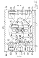
- Figure 1 is a cross-sectional view of a moulding station which incorporates a mould opening and closing mechanism according to the invention, the line I-I in Figure 2 indicating the section on which Figure 1 is taken, the station being shown in a mould open condition;
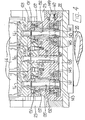
- Figure 2 is an underneath view of the moulding station taken in the direction of the arrow 2 in Figure 1 and showing the station in a mould closed condition;
- Figure 3 is a sectional view taken on the line III-III in Figure 1; and
- Figure 4 is a sectional view taken on the line IV-IV in Figure 1.
- The moulding station shown in the drawings comprises a mould opening and closing mechanism for use in opening and closing three moulds simultaneously by moving a
first portion 12 and asecond portion 14 of each mould into engagement with each other and with abottom mould portion 16 of that mould to form a completed mould. Themould portions mould portions mould portions 12 are arranged in a straight line as are themould portions 14 and thebottom mould portions 16. - The mould opening and closing mechanism comprises a
piston 18 andcylinder 20 assembly; thecylinder 20 of which is mounted on the underside of and depends from asupport plate 22 which is supported by aframework 23 of the mould station. The piston andcylinder assembly piston rod 24 thereof which depends from thepiston 18. Acrosshead 26 is fixedly mounted on thepiston rod 24 to be moved therewith. Thecrosshead 26 is pivotally connected on one side thereof (the left viewing Figures 1 and 2) to a system Df-links. - The system of links comprises a
first link 28 which is pivotally mounted on ahorizontal pivot pin 30 mounted on thecrosshead 26. Thefirst link 28 carries apivot pin 32 on which asecond link 34 of the system of links is pivotally mounted. The second link 34 (see Figure 2) is pivoted about a central region thereof on thepin 32 and is also pivoted on twofurther pivot pins link 34 is therefore pivotally connected at a central region thereof to the piston andcylinder assembly pivot pin 36 forms a pivotal connection between thelink 34 and athird link 40 of the system of links at an end portion of thelink 34. Thelink 40 is also pivotally connected to afirst lever 42 of the mechanism by means of apivot pin 44. Thepivot pin 38 is on the opposite side of thepivot pin 32 to thepivot pin 36 and forms a pivotal connection between thesecond link 34 and afourth link 46 of the system. The affective distance between thepivot pins pivot pins 32 and 36 (see Figure 2). Thus, thelink 34 is pivotally connected on one side of the central region thereof to thelever 42 and on the other side of the central region thereof and half the effective distance therefrom to thelink 46. Thefourth link 46 is pivotally connected at a central region thereof to thesecond link 34 by thepivot pin 38 and also has pivotal connections, on opposite sides of the central region thereof and equi-distant therefrom, to a fifth 48 and a sixth 50 link of the system. The pivotal connection between the fourth 46 and the fifth 48 links is by means of apivot pin 52 and the pivotal connection between the fourth 46 and the sixth 50 links is by means of apivot pin 54. Thefifth link 48 and thesixth link 50 are respectively pivotally connected to asecond lever 56 and athird lever 58 of the mechanism by means ofpivot pins - The three
levers framework 23, eachlever 42 56 and 58 being pivotal on aseparate pin 64. At an upper end portion thereof, each of thelevers levers block 72 by means of apin 74 and theblock 72 being pivotally connected to thesupport pin 76. - The piston, and
cylinder assembly levers pivot pins 64 so that the mould portion supports 66, 68 and 70 are moved and themould portions 12 are moved away from or towards thefurther mould portions 14, thereby opening or closing the moulds. The purpose of the system oflinks levers cylinder assembly levers blocks 72 and the'supports 66, 68 and 70 to the left. Since the supports 66, 68 and 70 carry themould portions 12, themould portions 12 also move to the left away from themould portions 14 so that the moulds are opened. On the other hand, upwards movement of thecrosshead 26 by the action of the piston andcylinder assembly levers mould portions 12 towards themould portions 14 and closing the mould. The system oflinks mould portions second link 34 equalises the pressure between thepivot pins pins pins fourth link 46 equalises the pressure between thepivot pins - The three mould supports 66, 68 and 70 are each arranged to support one of the
mould portions 12. Eachsupport intermediate support 80 is removably mounted with theprojection 78 received in a T-shaped slot (not shown) in thesupport 80. Theprojection 78 'is a loose fit in the T-shaped slot to allow thesupport 80 to move slightly sideways relative to thesupport projection 78 to support thesupport 80 on thesupport intermediate support 80 has anupstanding lip portion 82 over which ahook portion 84 of themould portion 12 fits to mount themould portion 12 on thesupport 80 and hence on thesupport bolt 86 also interconnects theintermediate support 80 and themould portion 12. - The
support intermediate support 80 define aspace 88,beneath theprojection 78, which serves to insulate themould portion 12 from thesupport levers space 88 through anaperture 90 in thesupport aperture 92 in theintermediate support 80. The air passing through theaperture 92 finally passes between cooling fins 94 (Figure 3) of themould portion 12. - The three mould portion supports 66, 68 and 70 are each mounted on a linear slideway so that operation of the piston and
cylinder assembly levers pivots 64 to cause the mould portion supports 66, 68 and 70 to move along the slideways to bring themould portions 12 supported thereby into engagement with themould portions 14. The central one 68 of thesupports plate 96 extends above the other two supports 66 and 70 and has two dependingportions 98 at end portions thereof which are each secured to aslide rail 100 which is slideable in agroove 102 in theframework 23. Therails 100 and, thegrooves 102 provide the slideway of thecentral support 68. The slideway of thesupport 66 is provided by one of theslide rails 100 which enters agroove 104 in thesupport 66 and by aslide rail 106 mounted on thecentral support 68 which enters agroove 108 in thesupport 66. The slideway of thesupport 70 is provided in identical manner to that of thesupport 66. Thus, thecentral support 68 is mounted on a slideway, formed by therails 100 and the groove 1.02 and the slideways of the other twosupports central support 68. This arrangement allows thesupports - In addition to its connection to the system of
links crosshead 26 is pivotally connected to afurther link 110 on the right hand side thereof (viewing Figures 1 and 2). Thecrosshead 26 has apivot pin 112 mounted thereon on which thelink 110 is pivoted. Thelink 110 is also pivotally connected, by means of apivot pin 114 to threefurther levers 116. The threefurther levers 116 are each connected at a lower end portion thereof to thelink 110 and are mounted for pivotal movement about a central portion thereof on a horizontal fixedpivot pin 118, all threelevers 116 being pivoted on thesame pin 118, thepin 118 is supported by theframework 23. At upper end portions thereof, the threelevers 116 are pivotally connected to a furthermould portion support 120 which is arranged to support the threemould portions 14. - The connection between each
lever 116 and thesupport 120 is identical and identical to that between thelevers supports lever 116 being pivotally connected to ablock 122 by means of apin 124 and theblock 122 being pivotally connected to thesupport 120. Thesupport 120 is mounted in a linear slideway (not shown) similar to that of thesupport 68 for movement towards or away from thesupport support 120 carries threeintermediate supports 123 which are identically arranged to theintermediate supports 80 and carry the threemould portions 14. The. arrangement is such that operation of the piston andcylinder assembly mould portion support 120 to move simultaneously towards each other so that themould portions cylinder assembly mould portions 12 and themould portions 14 towards or away from each other. The mould opening and closing mechanism is capable of rapid and accurate operation and achieves substantially equal mould closing pressures. - When the
mould portions bottom mould portion 16. Eachbottom mould portion 16 is supported by aplate 128 which hasapertures 129 in which hollowbosses 130 are received. Eachhollow boss 130 extends into themould portion 16 and is a loose fit in theaperture 129 so that theboss 130 and themould portion 16 can move slightly relative to theplate 128 to accommodate itself better to themould portions boss 130 communicates with avacuum pipe 132 so that vacuum can be applied to themould portion 16 if desired. The central one of thepipes 132 is mounted in asupport 134 on which theplate 128 rests and extends into a vertical bore in aportion 135 of theframework 23, with aseal 133 sealing the gap between thepipe 132 and the bore. The twoend pipes 132, however, (see Figure 4) are formed invertical spindles 137 which are clamped to thesupport 134 byscrews 131 and are slideable vertically in theportion 135. Thespindles 137 carry thesupport 134. Thesupport 134, and hence themould portion 16, is vertically adjustable by vertical movement of thespindles 137 between limits set by twostop screws 139 which project upwardly from theportion 135. Each of thespindles 137 has a screw-threadedlower portion 141 which is threadedly-received in a threadedbore 143 in agear 145 mounted for rotation in a recess in thesupport 135 so that, when thegears 145 are rotated, thespindles 141 and hence themould portions 16 are moved vertically. Aworm 147 meshes with bothgears 145 so that, when theworm 147 is turned by means of afitment 149, thegears 145 and hence thespindles 141 are moved together. Thesupport 134 is thus vertically adjustable by adjustment means to alter the height of theplate 128 to suit different sizes of mould. - When the
mould portions electrical contact members 136 mounted on themould portions electrical contact members 138 mounted on theframework 23 and urged bysprings 140 towards the contact .members 136. Thus, when the moulds are fully open, there is electrical contact between thecontact members contact members 136 are connected to temperature sensing means in the form of a thermocouple embedded in themould portion 12 or 14 (the thermocouples TC2 of thecentral mould portions mould portions crosshead 26 carries two spring devices 148 (Figures 1 and 2). Thedevices 148 press on aplate 150 of theframework 23 when themould portions cylinder 20 for mould portion removal, thedevices 148 move thecrosshead 26 upwards and hence move themould portions contact members portions
Claims (4)
Applications Claiming Priority (2)
| Application Number | Priority Date | Filing Date | Title |
|---|---|---|---|
| GB8106259 | 1981-02-27 | ||
| GB8106259 | 1981-02-27 |
Publications (2)
| Publication Number | Publication Date |
|---|---|
| EP0059573A1 true EP0059573A1 (en) | 1982-09-08 |
| EP0059573B1 EP0059573B1 (en) | 1984-12-05 |
Family
ID=10520026
Family Applications (2)
| Application Number | Title | Priority Date | Filing Date |
|---|---|---|---|
| EP82300875A Expired EP0059574B1 (en) | 1981-02-27 | 1982-02-22 | A method of cooling a mould |
| EP82300874A Expired EP0059573B1 (en) | 1981-02-27 | 1982-02-22 | Mould opening and closing mechanism |
Family Applications Before (1)
| Application Number | Title | Priority Date | Filing Date |
|---|---|---|---|
| EP82300875A Expired EP0059574B1 (en) | 1981-02-27 | 1982-02-22 | A method of cooling a mould |
Country Status (7)
| Country | Link |
|---|---|
| US (2) | US4448600A (en) |
| EP (2) | EP0059574B1 (en) |
| JP (2) | JPS58500161A (en) |
| AU (2) | AU547417B2 (en) |
| CA (2) | CA1192404A (en) |
| DE (2) | DE3261405D1 (en) |
| WO (2) | WO1982002883A1 (en) |
Cited By (11)
| Publication number | Priority date | Publication date | Assignee | Title |
|---|---|---|---|---|
| FR2538368A1 (en) * | 1982-12-22 | 1984-06-29 | Owens Illinois Inc | APPARATUS FOR OPENING AND CLOSING SEVERAL RIBBED MOLDS SIMULTANEOUSLY IN A CONFINED SPACE |
| EP0255329A1 (en) * | 1986-07-26 | 1988-02-03 | Emhart Industries, Inc. | Apparatus for holding mould side portions in a glassware forming machine |
| EP0275660A1 (en) * | 1987-01-06 | 1988-07-27 | Emhart Industries, Inc. | Moulding mechanism for a glassware forming machine |
| EP0330397A2 (en) * | 1988-02-22 | 1989-08-30 | Vhc Limited | Mold opening and closing mechanism for an individual section (I.S.) glassware forming machine |
| FR2770512A1 (en) * | 1997-11-06 | 1999-05-07 | Emhart Glass Sa | MOLD OPENING AND CLOSING MECHANISM FOR AN INDIVIDUAL SECTOR FORMING MACHINE |
| FR2770511A1 (en) * | 1997-11-06 | 1999-05-07 | Emhart Glass Sa | MOLD OPENING AND CLOSING MECHANISM FOR AN INDIVIDUAL SECTOR FORMING MACHINE |
| FR2770506A1 (en) * | 1997-11-06 | 1999-05-07 | Emhart Glass Sa | INDIVIDUAL SECTOR FORMING MACHINE AND ITS MOLD OPENING AND CLOSING MECHANISM |
| FR2770510A1 (en) * | 1997-11-06 | 1999-05-07 | Emhart Glass Sa | MOLD OPENING AND CLOSING MECHANISM FOR A FORMING MACHINE WITH INDIVIDUAL SECTIONS |
| FR2771083A1 (en) * | 1997-11-06 | 1999-05-21 | Emhart Glass Sa | MOLD OPENING AND CLOSING MECHANISM FOR INDIVIDUAL SECTOR FORMING MACHINE |
| FR2771734A1 (en) * | 1997-11-06 | 1999-06-04 | Emhart Glass Sa | Mould operating mechanism for glassware forming machine |
| FR2782509A1 (en) * | 1998-08-19 | 2000-02-25 | Emhart Glass Mach Invest | Mold opening and closing mechanisms of individual section machine for glass bottle production |
Families Citing this family (12)
| Publication number | Priority date | Publication date | Assignee | Title |
|---|---|---|---|---|
| GB2172591B (en) * | 1985-03-19 | 1988-07-13 | Emhart Ind | Mould opening and closing mechanism for a glassware forming machine |
| GB9202706D0 (en) * | 1992-02-08 | 1992-03-25 | Emhart Glass Mach Invest | Mould mechanism |
| US5358542A (en) * | 1992-12-09 | 1994-10-25 | American National Can Company | Glass container forming machine including neck ring mold cooling |
| US7698907B1 (en) * | 1996-07-15 | 2010-04-20 | Owens-Brockway Glass Container Inc. | Mold assembly for glass articles |
| US5900035A (en) * | 1997-08-11 | 1999-05-04 | Owens-Brockway Glass Container Inc. | Glass forming machine blank mold cooling apparatus |
| US5891209A (en) * | 1997-11-06 | 1999-04-06 | Emhart Glass S.A. | Mold opening and closing mechanism for an I. S. machine |
| US5803945A (en) * | 1997-11-06 | 1998-09-08 | Emhart Glass Machinery Investments Inc. | Mold opening and closing mechanism for an I.S. machine |
| US5902370A (en) * | 1997-11-06 | 1999-05-11 | Emhart Glass S.A. | Mold opening and closing mechanism for an I S machine |
| US5824131A (en) * | 1997-11-06 | 1998-10-20 | Emhart Glass Machinery Investments Inc. | Mold opening and closing mechanism for an I.S. machine |
| IT1390911B1 (en) * | 2008-07-17 | 2011-10-19 | Bottero Spa | GROUP FOR OPENING / CLOSING MOLDS OF A MACHINE FOR FORMING GLASS ITEMS |
| SG11201807057UA (en) | 2016-03-10 | 2018-09-27 | Vitro Sab De Cv | Method and mechanism for opening and closing moulds for a machine for forming glass items |
| US10807899B2 (en) * | 2018-11-20 | 2020-10-20 | Owens-Brockway Glass Container Inc. | Temperature measurement system for blank molds in glassware forming machines |
Citations (4)
| Publication number | Priority date | Publication date | Assignee | Title |
|---|---|---|---|---|
| FR813789A (en) * | 1935-11-20 | 1937-06-08 | Improvements in machines for molding glassware or other articles obtained from a molten material which solidifies on cooling | |
| US3721545A (en) * | 1969-06-25 | 1973-03-20 | Owens Illinois Inc | Multiple-cavity glass mold opening apparatus |
| US4009016A (en) * | 1973-11-23 | 1977-02-22 | Emhart Industries, Inc. | Method of making glassware with a high speed press and blow technique |
| FR2383136A1 (en) * | 1977-03-07 | 1978-10-06 | Owens Illinois Inc | GLASS CONTAINER FORMING MACHINES |
Family Cites Families (17)
| Publication number | Priority date | Publication date | Assignee | Title |
|---|---|---|---|---|
| GB466117A (en) * | 1935-11-20 | 1937-05-20 | Thomas Finney Pearson | Improvements in or relating to moulding machines for glassware or other articles made from molten material which sets on cooling |
| US3133807A (en) * | 1961-06-09 | 1964-05-19 | Owens Illinois Glass Co | Mold cooling apparatus |
| DE1613349A1 (en) * | 1967-05-06 | 1970-05-21 | Quick Rotan Becker & Notz Kg | Electromagnetically switchable multi-stage clutch motor |
| US3607207A (en) * | 1969-02-18 | 1971-09-21 | Emhart Corp | Triple gob mold holder arm construction |
| US3586491A (en) * | 1969-04-23 | 1971-06-22 | Owens Illinois Inc | Mold cooling apparatus for glass forming machine |
| US3617233A (en) * | 1969-05-08 | 1971-11-02 | Owens Illinois Inc | Glass-forming machine |
| US3666433A (en) * | 1970-07-08 | 1972-05-30 | Emhart Corp | Mold holder with thermostatically controlled mold |
| US3967946A (en) * | 1972-12-15 | 1976-07-06 | Emhart Corporation | Mold holder arms for glassware forming machine and method of operating the same |
| GB1491859A (en) * | 1973-11-23 | 1977-11-16 | Emhart Ind | Glassware forming machines |
| US3888647A (en) * | 1974-04-15 | 1975-06-10 | Maul Bros Inc | Air cooled annular parison blank mold |
| GB1537837A (en) * | 1975-05-28 | 1979-01-04 | Emhart Ind | Glassware forming machines |
| US4009018A (en) * | 1975-07-07 | 1977-02-22 | Emhart Industries, Inc. | Glassware forming machine of the I. S. type with in-line mold motion |
| DE2609651C2 (en) * | 1976-03-09 | 1978-04-13 | Fa. Hermann Heye, 4962 Obernkirchen | Molding tool for molten gas |
| JPS5511615A (en) * | 1978-07-10 | 1980-01-26 | Nippon Telegr & Teleph Corp <Ntt> | Mis field effective type transistor analog signal amplifier circuit |
| US4261724A (en) * | 1979-10-29 | 1981-04-14 | Emhart Industries, Inc. | Triple gob blowhead or baffle construction |
| DE3040311C2 (en) * | 1980-10-25 | 1982-09-16 | Fa. Hermann Heye, 3063 Obernkirchen | Cooling device for a molding tool |
| DE3040310C1 (en) * | 1980-10-25 | 1982-03-25 | Heye Hermann Fa | Pressure fluid distribution device for a mold for processing glass and similar thermoplastic materials |
-
1982
- 1982-02-22 US US06/433,140 patent/US4448600A/en not_active Expired - Lifetime
- 1982-02-22 AU AU81408/82A patent/AU547417B2/en not_active Ceased
- 1982-02-22 EP EP82300875A patent/EP0059574B1/en not_active Expired
- 1982-02-22 EP EP82300874A patent/EP0059573B1/en not_active Expired
- 1982-02-22 US US06/433,123 patent/US4505730A/en not_active Expired - Lifetime
- 1982-02-22 JP JP57500664A patent/JPS58500161A/en active Granted
- 1982-02-22 DE DE8282300874T patent/DE3261405D1/en not_active Expired
- 1982-02-22 DE DE8282300875T patent/DE3261729D1/en not_active Expired
- 1982-02-22 AU AU81416/82A patent/AU547425B2/en not_active Ceased
- 1982-02-22 WO PCT/GB1982/000057 patent/WO1982002883A1/en unknown
- 1982-02-22 JP JP57500668A patent/JPS58500117A/en active Pending
- 1982-02-22 WO PCT/GB1982/000049 patent/WO1982002877A1/en unknown
- 1982-02-25 CA CA000397059A patent/CA1192404A/en not_active Expired
- 1982-02-25 CA CA000397060A patent/CA1192405A/en not_active Expired
Patent Citations (5)
| Publication number | Priority date | Publication date | Assignee | Title |
|---|---|---|---|---|
| FR813789A (en) * | 1935-11-20 | 1937-06-08 | Improvements in machines for molding glassware or other articles obtained from a molten material which solidifies on cooling | |
| US3721545A (en) * | 1969-06-25 | 1973-03-20 | Owens Illinois Inc | Multiple-cavity glass mold opening apparatus |
| US4009016A (en) * | 1973-11-23 | 1977-02-22 | Emhart Industries, Inc. | Method of making glassware with a high speed press and blow technique |
| FR2383136A1 (en) * | 1977-03-07 | 1978-10-06 | Owens Illinois Inc | GLASS CONTAINER FORMING MACHINES |
| US4137061A (en) * | 1977-03-07 | 1979-01-30 | Owens-Illinois, Inc. | Apparatus for forming glass containers |
Cited By (14)
| Publication number | Priority date | Publication date | Assignee | Title |
|---|---|---|---|---|
| FR2538368A1 (en) * | 1982-12-22 | 1984-06-29 | Owens Illinois Inc | APPARATUS FOR OPENING AND CLOSING SEVERAL RIBBED MOLDS SIMULTANEOUSLY IN A CONFINED SPACE |
| EP0255329A1 (en) * | 1986-07-26 | 1988-02-03 | Emhart Industries, Inc. | Apparatus for holding mould side portions in a glassware forming machine |
| EP0275660A1 (en) * | 1987-01-06 | 1988-07-27 | Emhart Industries, Inc. | Moulding mechanism for a glassware forming machine |
| EP0330397A2 (en) * | 1988-02-22 | 1989-08-30 | Vhc Limited | Mold opening and closing mechanism for an individual section (I.S.) glassware forming machine |
| EP0330397A3 (en) * | 1988-02-22 | 1990-08-29 | Maul Technology Co. | Mold opening and closing mechanism for an individual section (i.s.) glassware forming machine |
| FR2770512A1 (en) * | 1997-11-06 | 1999-05-07 | Emhart Glass Sa | MOLD OPENING AND CLOSING MECHANISM FOR AN INDIVIDUAL SECTOR FORMING MACHINE |
| FR2770511A1 (en) * | 1997-11-06 | 1999-05-07 | Emhart Glass Sa | MOLD OPENING AND CLOSING MECHANISM FOR AN INDIVIDUAL SECTOR FORMING MACHINE |
| FR2770506A1 (en) * | 1997-11-06 | 1999-05-07 | Emhart Glass Sa | INDIVIDUAL SECTOR FORMING MACHINE AND ITS MOLD OPENING AND CLOSING MECHANISM |
| FR2770510A1 (en) * | 1997-11-06 | 1999-05-07 | Emhart Glass Sa | MOLD OPENING AND CLOSING MECHANISM FOR A FORMING MACHINE WITH INDIVIDUAL SECTIONS |
| FR2771083A1 (en) * | 1997-11-06 | 1999-05-21 | Emhart Glass Sa | MOLD OPENING AND CLOSING MECHANISM FOR INDIVIDUAL SECTOR FORMING MACHINE |
| FR2771404A1 (en) * | 1997-11-06 | 1999-05-28 | Emhart Glass Sa | MOLD SUPPORT ASSEMBLY FOR INDIVIDUAL SECTION FORMING MACHINE |
| FR2771734A1 (en) * | 1997-11-06 | 1999-06-04 | Emhart Glass Sa | Mould operating mechanism for glassware forming machine |
| FR2771730A1 (en) * | 1997-11-06 | 1999-06-04 | Emhart Glass Sa | INDIVIDUAL SECTOR TRAINING MACHINE |
| FR2782509A1 (en) * | 1998-08-19 | 2000-02-25 | Emhart Glass Mach Invest | Mold opening and closing mechanisms of individual section machine for glass bottle production |
Also Published As
| Publication number | Publication date |
|---|---|
| DE3261405D1 (en) | 1985-01-17 |
| AU547417B2 (en) | 1985-10-17 |
| EP0059574A1 (en) | 1982-09-08 |
| DE3261729D1 (en) | 1985-02-14 |
| JPH0153208B2 (en) | 1989-11-13 |
| CA1192405A (en) | 1985-08-27 |
| AU8141682A (en) | 1982-09-14 |
| JPS58500117A (en) | 1983-01-20 |
| EP0059574B1 (en) | 1985-01-02 |
| AU547425B2 (en) | 1985-10-17 |
| AU8140882A (en) | 1982-09-14 |
| JPS58500161A (en) | 1983-02-03 |
| WO1982002877A1 (en) | 1982-09-02 |
| US4448600A (en) | 1984-05-15 |
| CA1192404A (en) | 1985-08-27 |
| EP0059573B1 (en) | 1984-12-05 |
| WO1982002883A1 (en) | 1982-09-02 |
| US4505730A (en) | 1985-03-19 |
Similar Documents
| Publication | Publication Date | Title |
|---|---|---|
| US4448600A (en) | Mould opening and closing mechanism | |
| EP0153534B1 (en) | Mould arrangement for a cyclicly operating glassware forming machine | |
| US4443241A (en) | Method of and apparatus for monitoring the closing action of a mould | |
| EP0195599B1 (en) | Mould opening and closing mechanism for a glassware forming machine | |
| US4701202A (en) | Moulding apparatus for glassware forming machine | |
| EP0102820B1 (en) | Mould arrangement for glassware forming machine | |
| CN108473352B (en) | Mold cooling system and method for hollow glass article forming machine | |
| US5931982A (en) | Baffle mechanism for an I.S. machine | |
| GB2331079A (en) | Takeout mechanism for an I.S. machine | |
| GB2331093A (en) | Mold opening and closing mechanism using electronic motors with position determination | |
| US4695307A (en) | Baffle moving mechanism for use in a glassware manufacturing machine of the individual section type | |
| AU735227B2 (en) | I.S. machine | |
| AU735225B2 (en) | Plunger mechanis for an I.S. machine | |
| US5902370A (en) | Mold opening and closing mechanism for an I S machine | |
| US5868813A (en) | I. S. machine | |
| US5833731A (en) | I S machine | |
| US5858049A (en) | Plunger mechanism for an I.S. machine | |
| AU733505B2 (en) | Plunger base module for a plunger mechanism of an I.S. machine | |
| GB2331077A (en) | Invert and neck ring holder mechanism with sensors | |
| AU733548B2 (en) | Invert and neck ring holder mechanism for an I.S. machine | |
| AU735224B2 (en) | Mold carrier assembly for an I.S. machine mold opening and closing mechanism | |
| GB2331082A (en) | I. S. machine with four independent drives for mould carriers | |
| GB2331090A (en) | Mold opening and closing mechanism incorporating a rotary drive | |
| AU736890B2 (en) | Mold opening and closing mechanism for an I.S. machine | |
| AU741542B2 (en) | Plunger mechanism for an I.S. machine |
Legal Events
| Date | Code | Title | Description |
|---|---|---|---|
| PUAI | Public reference made under article 153(3) epc to a published international application that has entered the european phase |
Free format text: ORIGINAL CODE: 0009012 |
|
| AK | Designated contracting states |
Designated state(s): BE DE FR GB IT |
|
| 17P | Request for examination filed |
Effective date: 19830216 |
|
| ITF | It: translation for a ep patent filed |
Owner name: UFFICIO BREVETTI RICCARDI & C. |
|
| GRAA | (expected) grant |
Free format text: ORIGINAL CODE: 0009210 |
|
| AK | Designated contracting states |
Designated state(s): BE DE FR GB IT |
|
| REF | Corresponds to: |
Ref document number: 3261405 Country of ref document: DE Date of ref document: 19850117 |
|
| ET | Fr: translation filed | ||
| PLBE | No opposition filed within time limit |
Free format text: ORIGINAL CODE: 0009261 |
|
| STAA | Information on the status of an ep patent application or granted ep patent |
Free format text: STATUS: NO OPPOSITION FILED WITHIN TIME LIMIT |
|
| 26N | No opposition filed | ||
| PG25 | Lapsed in a contracting state [announced via postgrant information from national office to epo] |
Ref country code: BE Effective date: 19860228 |
|
| BERE | Be: lapsed |
Owner name: EMHART INDUSTRIES INC. Effective date: 19860228 |
|
| REG | Reference to a national code |
Ref country code: GB Ref legal event code: 732 |
|
| ITTA | It: last paid annual fee | ||
| REG | Reference to a national code |
Ref country code: FR Ref legal event code: TP |
|
| ITPR | It: changes in ownership of a european patent |
Owner name: CESSIONE;EMHART GLASS MACHINERY INC. |
|
| PGFP | Annual fee paid to national office [announced via postgrant information from national office to epo] |
Ref country code: FR Payment date: 19970115 Year of fee payment: 16 |
|
| PGFP | Annual fee paid to national office [announced via postgrant information from national office to epo] |
Ref country code: GB Payment date: 19970117 Year of fee payment: 16 Ref country code: DE Payment date: 19970117 Year of fee payment: 16 |
|
| PG25 | Lapsed in a contracting state [announced via postgrant information from national office to epo] |
Ref country code: GB Free format text: LAPSE BECAUSE OF NON-PAYMENT OF DUE FEES Effective date: 19980222 |
|
| PG25 | Lapsed in a contracting state [announced via postgrant information from national office to epo] |
Ref country code: FR Free format text: THE PATENT HAS BEEN ANNULLED BY A DECISION OF A NATIONAL AUTHORITY Effective date: 19980228 |
|
| GBPC | Gb: european patent ceased through non-payment of renewal fee |
Effective date: 19980222 |
|
| PG25 | Lapsed in a contracting state [announced via postgrant information from national office to epo] |
Ref country code: DE Free format text: LAPSE BECAUSE OF NON-PAYMENT OF DUE FEES Effective date: 19981103 |
|
| REG | Reference to a national code |
Ref country code: FR Ref legal event code: ST |