EP0059203B1 - A coupling - Google Patents
A coupling Download PDFInfo
- Publication number
- EP0059203B1 EP0059203B1 EP81902439A EP81902439A EP0059203B1 EP 0059203 B1 EP0059203 B1 EP 0059203B1 EP 81902439 A EP81902439 A EP 81902439A EP 81902439 A EP81902439 A EP 81902439A EP 0059203 B1 EP0059203 B1 EP 0059203B1
- Authority
- EP
- European Patent Office
- Prior art keywords
- coupling
- column
- members
- tightening
- boring machine
- Prior art date
- Legal status (The legal status is an assumption and is not a legal conclusion. Google has not performed a legal analysis and makes no representation as to the accuracy of the status listed.)
- Expired
Links
- 230000008878 coupling Effects 0.000 title claims abstract description 41
- 238000010168 coupling process Methods 0.000 title claims abstract description 41
- 238000005859 coupling reaction Methods 0.000 title claims abstract description 41
- 238000006073 displacement reaction Methods 0.000 claims 1
- 239000000969 carrier Substances 0.000 description 2
- 239000000463 material Substances 0.000 description 2
- 229910000838 Al alloy Inorganic materials 0.000 description 1
- 230000000712 assembly Effects 0.000 description 1
- 238000000429 assembly Methods 0.000 description 1
- 230000005540 biological transmission Effects 0.000 description 1
- 230000009977 dual effect Effects 0.000 description 1
- 230000004048 modification Effects 0.000 description 1
- 238000012986 modification Methods 0.000 description 1
- 238000007789 sealing Methods 0.000 description 1
Images

Classifications
-
- F—MECHANICAL ENGINEERING; LIGHTING; HEATING; WEAPONS; BLASTING
- F16—ENGINEERING ELEMENTS AND UNITS; GENERAL MEASURES FOR PRODUCING AND MAINTAINING EFFECTIVE FUNCTIONING OF MACHINES OR INSTALLATIONS; THERMAL INSULATION IN GENERAL
- F16B—DEVICES FOR FASTENING OR SECURING CONSTRUCTIONAL ELEMENTS OR MACHINE PARTS TOGETHER, e.g. NAILS, BOLTS, CIRCLIPS, CLAMPS, CLIPS OR WEDGES; JOINTS OR JOINTING
- F16B2/00—Friction-grip releasable fastenings
- F16B2/02—Clamps, i.e. with gripping action effected by positive means other than the inherent resistance to deformation of the material of the fastening
- F16B2/18—Clamps, i.e. with gripping action effected by positive means other than the inherent resistance to deformation of the material of the fastening using cams, levers, eccentrics, or toggles
-
- B—PERFORMING OPERATIONS; TRANSPORTING
- B28—WORKING CEMENT, CLAY, OR STONE
- B28D—WORKING STONE OR STONE-LIKE MATERIALS
- B28D1/00—Working stone or stone-like materials, e.g. brick, concrete or glass, not provided for elsewhere; Machines, devices, tools therefor
- B28D1/02—Working stone or stone-like materials, e.g. brick, concrete or glass, not provided for elsewhere; Machines, devices, tools therefor by sawing
- B28D1/04—Working stone or stone-like materials, e.g. brick, concrete or glass, not provided for elsewhere; Machines, devices, tools therefor by sawing with circular or cylindrical saw-blades or saw-discs
- B28D1/041—Working stone or stone-like materials, e.g. brick, concrete or glass, not provided for elsewhere; Machines, devices, tools therefor by sawing with circular or cylindrical saw-blades or saw-discs with cylinder saws, e.g. trepanning; saw cylinders, e.g. having their cutting rim equipped with abrasive particles
-
- F—MECHANICAL ENGINEERING; LIGHTING; HEATING; WEAPONS; BLASTING
- F16—ENGINEERING ELEMENTS AND UNITS; GENERAL MEASURES FOR PRODUCING AND MAINTAINING EFFECTIVE FUNCTIONING OF MACHINES OR INSTALLATIONS; THERMAL INSULATION IN GENERAL
- F16B—DEVICES FOR FASTENING OR SECURING CONSTRUCTIONAL ELEMENTS OR MACHINE PARTS TOGETHER, e.g. NAILS, BOLTS, CIRCLIPS, CLAMPS, CLIPS OR WEDGES; JOINTS OR JOINTING
- F16B7/00—Connections of rods or tubes, e.g. of non-circular section, mutually, including resilient connections
- F16B7/04—Clamping or clipping connections
- F16B7/044—Clamping or clipping connections for rods or tubes being in angled relationship
- F16B7/0446—Clamping or clipping connections for rods or tubes being in angled relationship for tubes using the innerside thereof
- F16B7/0453—Clamping or clipping connections for rods or tubes being in angled relationship for tubes using the innerside thereof the tubes being drawn towards each other
- F16B7/046—Clamping or clipping connections for rods or tubes being in angled relationship for tubes using the innerside thereof the tubes being drawn towards each other by rotating an eccenter-mechanism
-
- F—MECHANICAL ENGINEERING; LIGHTING; HEATING; WEAPONS; BLASTING
- F16—ENGINEERING ELEMENTS AND UNITS; GENERAL MEASURES FOR PRODUCING AND MAINTAINING EFFECTIVE FUNCTIONING OF MACHINES OR INSTALLATIONS; THERMAL INSULATION IN GENERAL
- F16B—DEVICES FOR FASTENING OR SECURING CONSTRUCTIONAL ELEMENTS OR MACHINE PARTS TOGETHER, e.g. NAILS, BOLTS, CIRCLIPS, CLAMPS, CLIPS OR WEDGES; JOINTS OR JOINTING
- F16B7/00—Connections of rods or tubes, e.g. of non-circular section, mutually, including resilient connections
- F16B7/04—Clamping or clipping connections
- F16B7/0406—Clamping or clipping connections for rods or tubes being coaxial
- F16B7/0413—Clamping or clipping connections for rods or tubes being coaxial for tubes using the innerside thereof
-
- Y—GENERAL TAGGING OF NEW TECHNOLOGICAL DEVELOPMENTS; GENERAL TAGGING OF CROSS-SECTIONAL TECHNOLOGIES SPANNING OVER SEVERAL SECTIONS OF THE IPC; TECHNICAL SUBJECTS COVERED BY FORMER USPC CROSS-REFERENCE ART COLLECTIONS [XRACs] AND DIGESTS
- Y10—TECHNICAL SUBJECTS COVERED BY FORMER USPC
- Y10T—TECHNICAL SUBJECTS COVERED BY FORMER US CLASSIFICATION
- Y10T403/00—Joints and connections
- Y10T403/70—Interfitted members
- Y10T403/7075—Interfitted members including discrete retainer
- Y10T403/7077—Interfitted members including discrete retainer for telescoping members
- Y10T403/7079—Transverse pin
- Y10T403/7086—Wedge pin
-
- Y—GENERAL TAGGING OF NEW TECHNOLOGICAL DEVELOPMENTS; GENERAL TAGGING OF CROSS-SECTIONAL TECHNOLOGIES SPANNING OVER SEVERAL SECTIONS OF THE IPC; TECHNICAL SUBJECTS COVERED BY FORMER USPC CROSS-REFERENCE ART COLLECTIONS [XRACs] AND DIGESTS
- Y10—TECHNICAL SUBJECTS COVERED BY FORMER USPC
- Y10T—TECHNICAL SUBJECTS COVERED BY FORMER US CLASSIFICATION
- Y10T403/00—Joints and connections
- Y10T403/75—Joints and connections having a joining piece extending through aligned openings in plural members
-
- Y—GENERAL TAGGING OF NEW TECHNOLOGICAL DEVELOPMENTS; GENERAL TAGGING OF CROSS-SECTIONAL TECHNOLOGIES SPANNING OVER SEVERAL SECTIONS OF THE IPC; TECHNICAL SUBJECTS COVERED BY FORMER USPC CROSS-REFERENCE ART COLLECTIONS [XRACs] AND DIGESTS
- Y10—TECHNICAL SUBJECTS COVERED BY FORMER USPC
- Y10T—TECHNICAL SUBJECTS COVERED BY FORMER US CLASSIFICATION
- Y10T408/00—Cutting by use of rotating axially moving tool
- Y10T408/91—Machine frame
-
- Y—GENERAL TAGGING OF NEW TECHNOLOGICAL DEVELOPMENTS; GENERAL TAGGING OF CROSS-SECTIONAL TECHNOLOGIES SPANNING OVER SEVERAL SECTIONS OF THE IPC; TECHNICAL SUBJECTS COVERED BY FORMER USPC CROSS-REFERENCE ART COLLECTIONS [XRACs] AND DIGESTS
- Y10—TECHNICAL SUBJECTS COVERED BY FORMER USPC
- Y10T—TECHNICAL SUBJECTS COVERED BY FORMER US CLASSIFICATION
- Y10T408/00—Cutting by use of rotating axially moving tool
- Y10T408/94—Tool-support
Definitions
- the invention is related to a coupling to connect rod-like or tubular components in order to form a column, said components comprising a female and a male member having co-operating wedge surfaces, which are movable into and out of contact with each other by generally axial relative movement of the members, said coupling comprising means to urge the wedge surfaces into intimate contact with each other upon tightening of the coupling and spring means for maintaining the tightened state of the coupling.
- Such a coupling is advantageous for erecting guides for boring machines.
- Such a coupling is disclosed in the Swedish patent 157 300 and comprises a pre-tensioned spring, which only has the purpose to maintain the connection should the tightening means formed by an eccentric be un- deliberately released. When the locking by the eccentric is correct, the spring has no function. The tension of the spring is reduced on tightening of the coupling.
- the object of the invention is to improve this coupling so that the spring always will have a certain influence on the maintaining of the tightened state of the coupling.
- This object is obtained in that the spring is adapted, upon tightening of the coupling, to accumulate spring force urging the wedge surfaces of the members towards each other.
- the tensioning means and the spring will act in "series” so that the tightening will give rise to the spring force.
- the tightening means and the spring function in parallel.
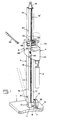
- the boring assembly illustrated in Fig. 1 includes a bottom plate 1, a column 2, a boring tool 3, a boring machine member 4, which drives the tool, and a feed member 5, on which the boring machine member 4 is mounted.
- the bottom plate 1 may in practice be constructed from aluminium alloy and may, at its lower side, have a conventional endless sealing ring, which confines a space from which the air may be evacuated so as to obtain a vacuum by means of which the plate is adhered to and rigidly anchored relative to the ground, e.g. a floor.
- connection 6 of conical type, which allows rotation of column 2 relative to the bottom plate as indicated by the dashed lines in the figure.
- the connection 6 comprises two halves 7 and 8, the first-mentioned half 7 being rigidly connected to bottom plate 1 through a socket 9 and comprising a conical female recess (not visible) in which a male projection, which in a corresponding manner is conical, on the half 8 is introduced, the half 8 being in turn rigidly connected to a hollow shaft portion 10 projecting sidewardly and attached to the lower portion 11 of the column.
- a tightening bolt 12 extends through the center of the shaft 10 and is threadedly connected to the female connection half 7.
- the column 2 may, as mentioned, be assembled by several elements, two of which are illustrated in Fig. 1, namely elements 13, 14. These elements are identically designed except that their length differs.
- each element is prepared from a rectangular tube having comparatively large wall thickness, e.g. in the order of 3-4 mm.
- a rack 15 (see element 13) is provided along one wall of the tube, said rack extending all along the element and forming, together with a corresponding rack of the adjacent element (see rack 15' on element 14), a continuous cogway all along the column in its assembled state.
- the cogway formed by racks 15, 15' is generally centrally arranged along the tube wall so that planar runways 16, 17 are formed on opposite sides of the cogway for rotary members in feed member 5.
- the tube elements 13, 14 are interconnected through a coupling illustrated in detail in Figs. 3 and 4, said coupling including a female member at the lower end of each column tube element and a male element at the upper end of each tube element.
- the male member in the coupling is denoted 18 while the female member is denoted 19.
- the male member 18 has a wedge surface formed by an external conical surface 20, while the female member 19 has an internal conical surface 21 with generally the same conicity as surface 20.
- Female member 19 is formed by a tubular body which is welded or otherwise rigidly connected to the lower part of the column element, e.g. the tube 14.
- the male member 18 comprises two elements movable relative to each other along axis 22, namely a first element 23 comprising the conical surface 20, said element being welded or otherwise anchored to the upper end of the column element 13, and a second element formed by a head, a pull rod 25 having a thread 26 projecting downwardly from the lower side of the head.
- a nut 27 is engaged with the thread and between the nut and a downwardly directed abutment surface 28 of element 23 there is a strong disc spring 29 urging to maintain the head 24 against an upwardly directed annular abutment surface 30 of element 23.
- the female member 19 and movable head 24 of the male member have holes extending along the transverse axis 31. More specifically, the female member 19 has two diametrically opposed holes 32, 33, which are located on opposite sides of the female recess of the member and the first-mentioned of which has a larger diameter than the last-mentioned. In the head 24, there is a hole 34 having an oblong cross section.
- the holes 32, 33 are in this embodiment defined by bushings 35, 36.
- An eccentric 37 is introduced into the holes 32, 33, 34, said eccentric having two cylindrical and concentrical end portions 38, 39 located along the axis 31 and having different diameters to fit into corresponding holes in the female member and a cylindrical portion 40 located between the two end portions and having a center axis being eccentric relative to axis 31 common to the end portion.
- a recess 41 e.g. rectangular, provided for a suitable operating handle or key.
- the coupling described operates in the following way.
- the eccentric Prior to assembly of the tube elements 13, 14 provided with the male and female members, the eccentric is separated from other coupling parts.
- the male and female members are provisionally moved together so that the two transverse holes 32, 33 of the female member are generally aligned with transverse hole 34 in the head 24 of the male member.
- the eccentric 37 is introduced into the holes so that the forward pinlike end portion 39 is engaged with hole 33.
- a rather small clearance between end portions 38, 39 and corresponding holes 32, 33 is at hand, while the clearance between intermediate portion 40 and corresponding hole 34 in head 24 may be rather large.
- the eccentric is now rotated about 90°, e.g. through operating handle 42 illustrated in Fig. 1.
- the non-conical lower half of the first element 23 of the male member protrudes somewhat above the upper end edge of the tube element 13 and the lower edge of female member 19 is located somewhat above the lower edge of the upper tube element 14.
- the exterior of element 23 is rectangular with the same cross section as the two tube elements 13, 14, which means that the two tube elements are prevented from rotation relative to each other when the rectangular section 23' of element 23 protrudes into the corresponding rectangular lower part of tube element 14.
- the coupling is released in following manner.
- the eccentric 37 is rotated at least 180° so that the eccentric intermediate portion 40 will act against the lower planar surface of the hole 34 in head 24, which means that head 24 urges the element 23 of male member 18 downwardly so that the frictional engagement between conical surfaces 20, 21 ceases. Subsequently, the eccentric 37 is removed from the holes and the male and female members may be separated.
- the eccentric may be operated from the side of tube element 14 in that the eccentric and the holes in which it may be introduced extend transversely relative to the length of the tube elements.
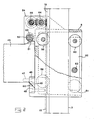
- the boring machine part 4 As appears from Fig. 1, the boring machine part 4 previously described is assembled from several components, namely a motor 43 indicated with dashed lines, a gearbox 44 and a frame portion 45, to which the gearbox is attached. As mentioned, the boring machine part 4 according to the invention is connected to the feed member 5, which is movable along the column, through a quick locking means. The features of this quick locking means appear specifically from Fig. 2, to which reference is made.
- the boring machine part or more specifically, the frame portion 45 thereof is only indicated to the left in the figure.
- the frame portion 45 is at the bottom provided with a rim 46 of wear resistant material.
- the rim may be attached to frame portion by screws 47 indicated with dashed lines in the figure.
- Rim 46 co-operates with a similar rim 48 screwed onto feed member 5. This cooperation is achieved via two inclined wedge-like surfaces, namely a first wedge surface 49 on rim 46 extending obliquely outwardly and downwardly from frame member 45 and a second wedge surface 50 on rim 48 extending obliquely upwardly and outwardly from feed member 5.
- frame portion 45 has a part inclined relative to the ground plane, a planar and inclined rim 51 of wear resistant material being provided on said part.
- This rim 51 co-operates with a tightening means formed by an eccentric 52 on feed member 5.
- the eccentric 52 may be formed by a body, which is cylindrical although partly planar at 53 and which at its opposite ends is eccentrically supported in those flanges or walls which pertain to feed member 5 and are denoted 54, 55 -in Fig. 1.
- Eccentric 52 is rotatable by handle 42 via a projection 56 having a recess.
- the boring machine part 4 is mounted on feed member 5 in the following manner:
- the eccentric 52 is rotated into the position indicated with dashed lines in Fig. 2, in which the planar surface 53 is facing downwardly.
- frame portion 45 is provisionally hooked onto feed member 5 by engaging the rims 46, 48.
- the frame portion is pivoted upwardly in a clockwise direction about the pivot center established at rims 46, 48 so that frame portion 45 assumes position of Fig. 2, in which the front face 57 of the frame portion abuts against a corresponding vertical surface of the feed member.
- This action may occur without interference from eccentric 52 in that rim 51 freely passes under the downwardly directed planar surface 53.
- the frame portion is finally tightened by rotating eccentric 52 180° to the position illustrated in full lines in Fig.
- the eccentric actuates the frame portion 45 with a force directed obliquely downwardly.
- the horizontal component of this force urges the frame portion inwardly towards feed member 5 and the vertical component is, at wedge surfaces 49, 50, divided in such a manner that also there a horizontal force component is obtained which urges the lower part of the frame portion towards feed member 5.
- the two wedge surfaces 49, 50 have the dual function to serve as a provisional attachment for the frame portion during mounting and to steadily wedge or press the frame portion against the feed member.
- feed member 5 is guided along column 2 via a number of rotary elements formed by wheels or rollers. More specifically, the feed member has four pairs 58, 59, 60 and 61 of wheels. Each wheel pair includes two wheels separated along the wheel axis. The two first-mentioned pairs of wheels 58, 59 which are arranged on one side of column 2 have the wheels in each pair located on opposite sides of rack 15, the wheels being adapted to roll along the runways 16, 17 in Fig. 1. These two pairs of wheels 58, 59 are stationarily supported relative to feed member 5, i.e. the wheels are rotatable relative to their axis of rotation but the axis is immovable relative to the side flanges 54, 55 of the feed member.
- wheel pairs 60, 61 located on the opposite side of the column are supported on a common carrier 62 formed by a bar which in turn is pivotably supported relative to frame member 5 via axis 63.
- the axes of wheel pairs 60, 61 are not directly connected to feed member 5. Since wheel pairs 60, 61 in this way are supported on a common carrier pivotable relative to feed member 5, it is ensured that both wheel pairs always abut the runway on the rear side of the column independently of any tendency of feed member to pivot about wheel pair 58 as a consequence of the torque imparted on the feed member from the counterforce from the boring tool 3 during boring. This means that any tendency to jamming of the feed member is eliminated; which in turn means that the force required from the operator to obtain a certain feed velocity of the boring tool is minimal.
- the axis 63 may preferably be adjustable and securable relative to the feed member as indicated with the dashed line in Fig. 2. This adjustability may be realized by designing the axis as part of an eccentric. The adjustability enables tightening of the wheel pairs 60, 61 towards wheel pairs 58, 59 so as to ensure contact of all wheel pairs against the runways without play. It is to be observed that the distance between wheel pair 61 and axis 63 is smaller than the distance between wheel pair 60 and the same axis.
- a gear arrangement which comprises two meshing gears 64, 65, the first-mentioned gear engaging the rack 15 while the latter has a transversal projection 66 (see Fig. 1) to which handle 42 may be connected.
- the tube elements to form the column 2 may be at hand in varying lengths as to enable erection of a column having a length corresponding to varying floor heights in buildings etc.
- the coupling described relative to Figs. 3 and 4 may be used in other connections than in a boring assembly.
- the coupling may be used with column-like or tubular components of the kind used in erecting scaffolds or tubular components for obtaining frames, e.g. building frames.
- other means e.g. wedges, which are introduced into and out of transversal holes in the members, may be used in all applications for tightening the male and female members.
- a common pivotable carrier may be applied not only on feed members for boring assemblies, but on any machine element movable along a longitudinal guide and at the same time subjected to torque.
- Arbitrary rotary members may be used instead of wheels arranged in pairs, e.g. simple rollers, balls etc.
- two separated first rotary members formed by wheel pairs 58, 59 are shown on one side of the column 2 and two separated second rotary members supported on the common pivotable carrier according to the invention.
- the number of first rotary members may be arbitrary, from one upwardly, while the number of second rotary elements may vary from two upwardly.
- first and second sets of rotary members may be pivotably connected to a main carrier common to two or more such carriers.
Landscapes
- Engineering & Computer Science (AREA)
- General Engineering & Computer Science (AREA)
- Mechanical Engineering (AREA)
- Mining & Mineral Resources (AREA)
- Earth Drilling (AREA)
- Snaps, Bayonet Connections, Set Pins, And Snap Rings (AREA)
- Mutual Connection Of Rods And Tubes (AREA)
- Mechanical Coupling Of Light Guides (AREA)
- Cable Accessories (AREA)
- Connections Effected By Soldering, Adhesion, Or Permanent Deformation (AREA)
Abstract
Description
- The invention is related to a coupling to connect rod-like or tubular components in order to form a column, said components comprising a female and a male member having co-operating wedge surfaces, which are movable into and out of contact with each other by generally axial relative movement of the members, said coupling comprising means to urge the wedge surfaces into intimate contact with each other upon tightening of the coupling and spring means for maintaining the tightened state of the coupling.
- Such a coupling is advantageous for erecting guides for boring machines.
- Such a coupling is disclosed in the Swedish patent 157 300 and comprises a pre-tensioned spring, which only has the purpose to maintain the connection should the tightening means formed by an eccentric be un- deliberately released. When the locking by the eccentric is correct, the spring has no function. The tension of the spring is reduced on tightening of the coupling.
- The object of the invention is to improve this coupling so that the spring always will have a certain influence on the maintaining of the tightened state of the coupling. This object is obtained in that the spring is adapted, upon tightening of the coupling, to accumulate spring force urging the wedge surfaces of the members towards each other. Thus, the tensioning means and the spring will act in "series" so that the tightening will give rise to the spring force. According to the above Swedish patent, the tightening means and the spring function in parallel.
- Other preferable features of the invention are defined in the appendant claims.
- -With reference to the appended drawings, a specific disclosure of a preferred embodiment will follow hereinafter.
- In the drawings:
- Fig. 1 is a perspective, partly simplified view of the boring assembly according to the invention;
- Fig. 2 is an enlarged section through a feed member of the assembly, a column and a boring machine member being illustrated partly cut;
- Fig. 3 is a section through a coupling between two members, which together form the column of the boring assembly; and
- Fig. 4 is a section IV-IV in Fig. 3.
- The boring assembly illustrated in Fig. 1 includes a
bottom plate 1, acolumn 2, aboring tool 3, aboring machine member 4, which drives the tool, and afeed member 5, on which theboring machine member 4 is mounted. - The
bottom plate 1 may in practice be constructed from aluminium alloy and may, at its lower side, have a conventional endless sealing ring, which confines a space from which the air may be evacuated so as to obtain a vacuum by means of which the plate is adhered to and rigidly anchored relative to the ground, e.g. a floor. - The
column 2 is connected tobottom plate 1 through aconnection 6 of conical type, which allows rotation ofcolumn 2 relative to the bottom plate as indicated by the dashed lines in the figure. More specifically, theconnection 6 comprises twohalves half 7 being rigidly connected tobottom plate 1 through asocket 9 and comprising a conical female recess (not visible) in which a male projection, which in a corresponding manner is conical, on thehalf 8 is introduced, thehalf 8 being in turn rigidly connected to ahollow shaft portion 10 projecting sidewardly and attached to thelower portion 11 of the column. A tighteningbolt 12 extends through the center of theshaft 10 and is threadedly connected to thefemale connection half 7. By tighteningbolt 12, the conical surfaces ofhalves bolt 12,column 2 will be free to pivot into any inclined position relative to the bottom plate and thereafter, the column may be fixed in said position by tighteningbolt 12. - The column 2 may, as mentioned, be assembled by several elements, two of which are illustrated in Fig. 1, namely
elements racks 15, 15' is generally centrally arranged along the tube wall so thatplanar runways feed member 5. - The
tube elements - Reference is now made to Figs. 3 and 4 illustrating the coupling according to the invention. In the drawing, the male member in the coupling is denoted 18 while the female member is denoted 19. The
male member 18 has a wedge surface formed by an externalconical surface 20, while thefemale member 19 has an internalconical surface 21 with generally the same conicity assurface 20.Female member 19 is formed by a tubular body which is welded or otherwise rigidly connected to the lower part of the column element, e.g. thetube 14. Themale member 18 comprises two elements movable relative to each other along axis 22, namely afirst element 23 comprising theconical surface 20, said element being welded or otherwise anchored to the upper end of thecolumn element 13, and a second element formed by a head, apull rod 25 having athread 26 projecting downwardly from the lower side of the head. Anut 27 is engaged with the thread and between the nut and a downwardly directedabutment surface 28 ofelement 23 there is astrong disc spring 29 urging to maintain thehead 24 against an upwardly directed annular abutment surface 30 ofelement 23. - The
female member 19 andmovable head 24 of the male member have holes extending along thetransverse axis 31. More specifically, thefemale member 19 has two diametrically opposedholes head 24, there is ahole 34 having an oblong cross section. Theholes bushings holes concentrical end portions axis 31 and having different diameters to fit into corresponding holes in the female member and acylindrical portion 40 located between the two end portions and having a center axis being eccentric relative toaxis 31 common to the end portion. - In the
larger end portion 38 of the eccentric, arecess 41, e.g. rectangular, provided for a suitable operating handle or key. - The coupling described operates in the following way. Prior to assembly of the
tube elements transverse holes transverse hole 34 in thehead 24 of the male member. In this position, the eccentric 37 is introduced into the holes so that the forwardpinlike end portion 39 is engaged withhole 33. A rather small clearance betweenend portions corresponding holes intermediate portion 40 andcorresponding hole 34 inhead 24 may be rather large. The eccentric is now rotated about 90°, e.g. throughoperating handle 42 illustrated in Fig. 1. This means that theconical surfaces spring 29 is tensioned by transmission of power through thehead 24, pullrod 25 andnut 27; which in turn means that eccentric 37 is safely maintained in the assumed position of rotation. - The non-conical lower half of the
first element 23 of the male member protrudes somewhat above the upper end edge of thetube element 13 and the lower edge offemale member 19 is located somewhat above the lower edge of theupper tube element 14. The exterior ofelement 23 is rectangular with the same cross section as the twotube elements element 23 protrudes into the corresponding rectangular lower part oftube element 14. - The coupling is released in following manner. The eccentric 37 is rotated at least 180° so that the eccentric
intermediate portion 40 will act against the lower planar surface of thehole 34 inhead 24, which means thathead 24 urges theelement 23 ofmale member 18 downwardly so that the frictional engagement betweenconical surfaces - It is to be observed that the eccentric may be operated from the side of
tube element 14 in that the eccentric and the holes in which it may be introduced extend transversely relative to the length of the tube elements. - With the coupling illustrated in Figs. 3 and 4 it is possible to erect boring frame columns from several elements in extremely limited time.
- Referring to Fig. 1, not only the
tube elements lower part 11 of the column and thetube element 13 are interconnected by such a coupling as indicated by eccentric 37' in Fig. 1. - As appears from Fig. 1, the
boring machine part 4 previously described is assembled from several components, namely amotor 43 indicated with dashed lines, agearbox 44 and aframe portion 45, to which the gearbox is attached. As mentioned, theboring machine part 4 according to the invention is connected to thefeed member 5, which is movable along the column, through a quick locking means. The features of this quick locking means appear specifically from Fig. 2, to which reference is made. - In Fig. 2, the boring machine part or more specifically, the
frame portion 45 thereof, is only indicated to the left in the figure. At its end facingfeed member 5, theframe portion 45 is at the bottom provided with arim 46 of wear resistant material. The rim may be attached to frame portion byscrews 47 indicated with dashed lines in the figure.Rim 46 co-operates with asimilar rim 48 screwed ontofeed member 5. This cooperation is achieved via two inclined wedge-like surfaces, namely afirst wedge surface 49 onrim 46 extending obliquely outwardly and downwardly fromframe member 45 and asecond wedge surface 50 onrim 48 extending obliquely upwardly and outwardly fromfeed member 5. - At the top,
frame portion 45 has a part inclined relative to the ground plane, a planar andinclined rim 51 of wear resistant material being provided on said part. Thisrim 51 co-operates with a tightening means formed by an eccentric 52 onfeed member 5. In practice, the eccentric 52 may be formed by a body, which is cylindrical although partly planar at 53 and which at its opposite ends is eccentrically supported in those flanges or walls which pertain to feedmember 5 and are denoted 54, 55 -in Fig. 1.Eccentric 52 is rotatable byhandle 42 via aprojection 56 having a recess. - The
boring machine part 4 is mounted onfeed member 5 in the following manner: The eccentric 52 is rotated into the position indicated with dashed lines in Fig. 2, in which theplanar surface 53 is facing downwardly. In this state,frame portion 45 is provisionally hooked ontofeed member 5 by engaging therims rims frame portion 45 assumes position of Fig. 2, in which the front face 57 of the frame portion abuts against a corresponding vertical surface of the feed member. This action may occur without interference from eccentric 52 in thatrim 51 freely passes under the downwardly directedplanar surface 53. The frame portion is finally tightened by rotating eccentric 52 180° to the position illustrated in full lines in Fig. 2, in which the eccentric actuates theframe portion 45 with a force directed obliquely downwardly. The horizontal component of this force urges the frame portion inwardly towardsfeed member 5 and the vertical component is, at wedge surfaces 49, 50, divided in such a manner that also there a horizontal force component is obtained which urges the lower part of the frame portion towardsfeed member 5. Thus, the twowedge surfaces - From Fig. 2 it also appears that
feed member 5 is guided alongcolumn 2 via a number of rotary elements formed by wheels or rollers. More specifically, the feed member has fourpairs wheels 58, 59 which are arranged on one side ofcolumn 2 have the wheels in each pair located on opposite sides ofrack 15, the wheels being adapted to roll along therunways wheels 58, 59 are stationarily supported relative to feedmember 5, i.e. the wheels are rotatable relative to their axis of rotation but the axis is immovable relative to theside flanges - The two other wheel pairs 60, 61 located on the opposite side of the column are supported on a
common carrier 62 formed by a bar which in turn is pivotably supported relative to framemember 5 viaaxis 63. Thus, the axes of wheel pairs 60, 61 are not directly connected to feedmember 5. Since wheel pairs 60, 61 in this way are supported on a common carrier pivotable relative to feedmember 5, it is ensured that both wheel pairs always abut the runway on the rear side of the column independently of any tendency of feed member to pivot aboutwheel pair 58 as a consequence of the torque imparted on the feed member from the counterforce from theboring tool 3 during boring. This means that any tendency to jamming of the feed member is eliminated; which in turn means that the force required from the operator to obtain a certain feed velocity of the boring tool is minimal. - The
axis 63, about whichcarrier 62 is pivotable, may preferably be adjustable and securable relative to the feed member as indicated with the dashed line in Fig. 2. This adjustability may be realized by designing the axis as part of an eccentric. The adjustability enables tightening of the wheel pairs 60, 61 towards wheel pairs 58, 59 so as to ensure contact of all wheel pairs against the runways without play. It is to be observed that the distance betweenwheel pair 61 andaxis 63 is smaller than the distance betweenwheel pair 60 and the same axis. This means that the force which is exerted onwheel pair 61 viaaxis 63 as a consequence of the torque acting upwardly on the feed member is greater than the corresponding force on thewheel pair 60 and thataxis 63 is comparatively close to thewheel pair 61 which first engages the runway, when the feed member is threaded ontocolumn 2. At said threading thewheel pair 61 is free to pivot relative toaxis 63 which is not the case when the upper wheel pair contacts the upper edge of the column. In order not to cause undue resistance during threading of the two upper wheel pairs 58, 60 it is, as illustrated in Fig. 2, preferable to have a lever as long as possible betweenaxis 63 andwheel pair 60. - To feed the
feed member 5 along the column, a gear arrangement is provided, which comprises two meshing gears 64, 65, the first-mentioned gear engaging therack 15 while the latter has a transversal projection 66 (see Fig. 1) to which handle 42 may be connected. - The tube elements to form the
column 2 may be at hand in varying lengths as to enable erection of a column having a length corresponding to varying floor heights in buildings etc. - The invention is of course not limited only to the embodiment described and illustrated. Thus, the coupling described relative to Figs. 3 and 4 may be used in other connections than in a boring assembly. E.g. the coupling may be used with column-like or tubular components of the kind used in erecting scaffolds or tubular components for obtaining frames, e.g. building frames. Instead of an eccentric of the kind described, other means, e.g. wedges, which are introduced into and out of transversal holes in the members, may be used in all applications for tightening the male and female members.
- The feature described with the aid of Fig. 2, i.e. to arrange the separated wheel pairs 60, 61 on a common pivotable carrier may be applied not only on feed members for boring assemblies, but on any machine element movable along a longitudinal guide and at the same time subjected to torque. Arbitrary rotary members may be used instead of wheels arranged in pairs, e.g. simple rollers, balls etc. In the embodiment described, two separated first rotary members formed by wheel pairs 58, 59 are shown on one side of the
column 2 and two separated second rotary members supported on the common pivotable carrier according to the invention. In the widest application of the invention, the number of first rotary members may be arbitrary, from one upwardly, while the number of second rotary elements may vary from two upwardly. Furthermore, it is possible to arrange the first and second sets of rotary members internally within a guide in the form of a groove having runways facing towards each other, against which the rotary members are pressed outwardly, instead of providing the rotary members on opposite sides of a central guide formed bycolumn 2. Two ormore carriers 62, each comprising at least two separated rotary members, may be pivotably connected to a main carrier common to two or more such carriers. - Also other modifications of the invention are conceivable within the scope of the appended claims.
Claims (9)
Priority Applications (1)
| Application Number | Priority Date | Filing Date | Title |
|---|---|---|---|
| AT81902439T ATE11325T1 (en) | 1980-09-05 | 1981-09-04 | COUPLING. |
Applications Claiming Priority (2)
| Application Number | Priority Date | Filing Date | Title |
|---|---|---|---|
| SE8006209A SE442960B (en) | 1980-09-05 | 1980-09-05 | LINING CONTROLLED MACHINE |
| SE8006209 | 1980-09-05 |
Publications (2)
| Publication Number | Publication Date |
|---|---|
| EP0059203A1 EP0059203A1 (en) | 1982-09-08 |
| EP0059203B1 true EP0059203B1 (en) | 1985-01-16 |
Family
ID=20341671
Family Applications (1)
| Application Number | Title | Priority Date | Filing Date |
|---|---|---|---|
| EP81902439A Expired EP0059203B1 (en) | 1980-09-05 | 1981-09-04 | A coupling |
Country Status (13)
| Country | Link |
|---|---|
| US (1) | US4500235A (en) |
| EP (1) | EP0059203B1 (en) |
| JP (1) | JPH0331923B2 (en) |
| BE (1) | BE890226A (en) |
| CA (1) | CA1171700A (en) |
| CH (2) | CH657551A5 (en) |
| DK (1) | DK151117C (en) |
| ES (1) | ES260203Y (en) |
| FI (1) | FI70984C (en) |
| IT (1) | IT1168550B (en) |
| NO (1) | NO153187C (en) |
| SE (1) | SE442960B (en) |
| WO (1) | WO1982000863A1 (en) |
Cited By (1)
| Publication number | Priority date | Publication date | Assignee | Title |
|---|---|---|---|---|
| DE9211608U1 (en) * | 1992-08-28 | 1992-11-05 | Gregorio, Marcello Di, 6253 Hadamar | Mast or tube connectors, especially for connecting split stand tubes of parasols |
Families Citing this family (36)
| Publication number | Priority date | Publication date | Assignee | Title |
|---|---|---|---|---|
| DE3237057A1 (en) * | 1982-10-06 | 1984-04-12 | Hilti AG, 9494 Schaan | TRIPOD DRILL |
| DE3334753A1 (en) * | 1983-09-26 | 1985-06-27 | Hilti Ag, Schaan | TRIPOD DRILLING DEVICE |
| DE3525795C1 (en) * | 1985-07-19 | 1987-02-26 | Rueesch Ferd Ag | Device for template end ring assembly of screen printing cylinders |
| AT383843B (en) * | 1986-01-14 | 1987-08-25 | Frantl Conprojekt | NODE CONNECTION FOR RODWORKS |
| US4779856A (en) * | 1987-07-31 | 1988-10-25 | Robert Beeler | Teaching apparatus for determining proper measurements for connecting two pieces of pipe |
| SE465021B (en) * | 1989-11-27 | 1991-07-15 | Anders Johnsen | DEVICE FOR DISPOSABLE CONNECTION OF TWO PARTS |
| EP0667461B1 (en) * | 1994-02-09 | 1997-05-28 | Pcm Willen S.A. | Precision connection between two parts |
| FR2733024B1 (en) * | 1995-04-11 | 1997-05-30 | Commerciale Mecanique Et Tech | IMPROVED SLIDING SHUTTER FOR FLUID PIPES |
| US5725205A (en) * | 1996-05-14 | 1998-03-10 | Braid Sales And Marketing, Inc. | Door assembly apparatus having lift frame and translatable and rotatable component capture units |
| DE19703911B4 (en) * | 1997-02-03 | 2014-07-10 | Robert Bosch Gmbh | Drilling aid for a hand-held drill |
| DE10043429A1 (en) * | 2000-09-04 | 2002-03-14 | Hilti Ag | drilling |
| US20060201492A1 (en) * | 2002-03-18 | 2006-09-14 | Anthony Baratta | Methods and apparatus for movable machining tools including for wall saws |
| DE10237610A1 (en) * | 2002-08-16 | 2004-02-26 | Hilti Ag | Guide rail connector |
| DE10361120B4 (en) * | 2003-12-22 | 2013-11-14 | Haacon Hebetechnik Gmbh | Lifting and transporting device for a container |
| DE10361125B4 (en) * | 2003-12-22 | 2005-11-10 | Haacon Hebetechnik Gmbh | Device for coaxial connection of a first rod to a second rod |
| US20070163412A1 (en) * | 2006-01-15 | 2007-07-19 | Anthony Baratta | Methods and apparatus for movable machining tools, including for wall saws |
| DE202006020729U1 (en) | 2006-03-24 | 2009-08-27 | Atlanta Antriebssysteme E. Seidenspinner Gmbh & Co. Kg | Adjustment device for mounting racks |
| WO2008130283A1 (en) * | 2007-04-20 | 2008-10-30 | Husqvarna Aktiebolag | A dismountable joint for a tubular track |
| SE534811C2 (en) * | 2007-10-15 | 2011-12-27 | Husqvarna Ab | Drilling rig base with telescopic pillar and clutch |
| DE102007055716A1 (en) * | 2007-12-06 | 2009-06-10 | Hilti Aktiengesellschaft | Machine stand with machine coupling for a transportable machine tool |
| EP2234777B1 (en) * | 2008-01-04 | 2011-08-03 | Husqvarna Professional Outdoor Products Inc. | Drill column for a drill stand |
| DE102008025076B4 (en) * | 2008-05-26 | 2015-12-03 | Iht Automation Gmbh & Co. Kg | driving device |
| US20100327241A1 (en) | 2009-06-25 | 2010-12-30 | Tractive Ab | Jacking column for concrete drilling and cutting |
| SE534760C2 (en) | 2010-04-14 | 2011-12-13 | Anders Johnsen | Processing unit with transfer unit adjustable in different rotational positions |
| TW201213773A (en) * | 2010-09-17 | 2012-04-01 | Hon Hai Prec Ind Co Ltd | Levelness micro-adjustment device |
| US8292150B2 (en) | 2010-11-02 | 2012-10-23 | Tyco Healthcare Group Lp | Adapter for powered surgical devices |
| US9789600B2 (en) * | 2012-10-31 | 2017-10-17 | Husqvarna Ab | Spacer for spacing a tool from a tool stand |
| SE540764C2 (en) * | 2017-03-22 | 2018-11-06 | Johnsen Anders | A machining assembly comprising a first and a second electric motor, a drive unit and a feed module |
| CN111036959B (en) * | 2019-12-31 | 2024-12-10 | 台州职业技术学院 | A boring machine |
| CN111421157B (en) * | 2020-03-03 | 2023-05-12 | 山东汇创材料科技有限公司 | Automatic drilling device for steel part |
| EP3879128A1 (en) * | 2020-03-09 | 2021-09-15 | Hilti Aktiengesellschaft | Device for connecting a first and a second rail, and system comprising such a device and a first and a second rail |
| CN111648722A (en) * | 2020-06-06 | 2020-09-11 | 台州市木落自动化科技有限公司 | Rock drill auxiliary frame for vertical drilling |
| CN111804955B (en) * | 2020-07-29 | 2021-05-28 | 芜湖市强一金工技术有限公司 | A bearing cage drilling device for bearing production and processing |
| GB2610578B (en) | 2021-09-08 | 2025-03-26 | Black & Decker Inc | A power tool stand |
| GB2610576A (en) | 2021-09-08 | 2023-03-15 | Black & Decker Inc | A power tool stand |
| GB2610575A (en) * | 2021-09-08 | 2023-03-15 | Black & Decker Inc | A power tool stand |
Family Cites Families (9)
| Publication number | Priority date | Publication date | Assignee | Title |
|---|---|---|---|---|
| SE157300C1 (en) * | ||||
| CH212487A (en) * | 1939-06-14 | 1940-11-30 | Stieber Wilhelm Ing Dr | Detachable clamp connection. |
| US3301108A (en) * | 1965-03-24 | 1967-01-31 | Royal Typewriter Co Inc | Expanding and contracting mandrel |
| US3387865A (en) * | 1966-08-29 | 1968-06-11 | Northrop Corp | Drill string concept |
| US3576336A (en) * | 1969-11-19 | 1971-04-27 | Uniroyal Inc | Force transmitting system |
| US3656785A (en) * | 1970-03-14 | 1972-04-18 | Peter Oskar E | Hub-to-shaft connection |
| DE2250216A1 (en) * | 1972-10-13 | 1974-04-25 | Aqua Tropic Gmbh Erzeugung Und | FRAME OD. DGL. MADE FROM AT LEAST TWO IN PARTICULAR, CONTINUOUSLY CONNECTABLE AND REPRODUCTIBLE FRAME COMPONENTS |
| SU627922A1 (en) * | 1977-04-08 | 1978-10-15 | Fedorov Vladimir A | Collet chuck |
| SU709272A1 (en) * | 1977-12-28 | 1980-01-15 | Минский Филиал Производственного Объединения "Техэнергохимпром" | Expandable mandrel |
-
1980
- 1980-09-05 SE SE8006209A patent/SE442960B/en not_active IP Right Cessation
-
1981
- 1981-09-03 CA CA000385169A patent/CA1171700A/en not_active Expired
- 1981-09-04 US US06/380,666 patent/US4500235A/en not_active Expired - Lifetime
- 1981-09-04 BE BE0/205868A patent/BE890226A/en not_active IP Right Cessation
- 1981-09-04 JP JP56502871A patent/JPH0331923B2/ja not_active Expired - Lifetime
- 1981-09-04 CH CH4513/85A patent/CH657551A5/en not_active IP Right Cessation
- 1981-09-04 EP EP81902439A patent/EP0059203B1/en not_active Expired
- 1981-09-04 CH CH5705/81A patent/CH655027A5/en not_active IP Right Cessation
- 1981-09-04 WO PCT/SE1981/000249 patent/WO1982000863A1/en not_active Ceased
- 1981-09-04 IT IT83458/81A patent/IT1168550B/en active
- 1981-09-05 ES ES1981260203U patent/ES260203Y/en not_active Expired
-
1982
- 1982-05-04 DK DK199082A patent/DK151117C/en not_active IP Right Cessation
- 1982-05-05 NO NO821490A patent/NO153187C/en unknown
- 1982-05-05 FI FI821589A patent/FI70984C/en not_active IP Right Cessation
Non-Patent Citations (3)
| Title |
|---|
| Dubbels Taschenbuch für den Maschinenbau, Band 1, S. 596, Bild 27. * |
| Les mécanism dans la technique moderne, Tome 4, p. 482. * |
| Mechanisms, Linkages and Mech. Contr. p. 264, Fig. 2. * |
Cited By (1)
| Publication number | Priority date | Publication date | Assignee | Title |
|---|---|---|---|---|
| DE9211608U1 (en) * | 1992-08-28 | 1992-11-05 | Gregorio, Marcello Di, 6253 Hadamar | Mast or tube connectors, especially for connecting split stand tubes of parasols |
Also Published As
| Publication number | Publication date |
|---|---|
| CH655027A5 (en) | 1986-03-27 |
| CA1171700A (en) | 1984-07-31 |
| US4500235A (en) | 1985-02-19 |
| WO1982000863A1 (en) | 1982-03-18 |
| JPS57501791A (en) | 1982-10-07 |
| SE8006209L (en) | 1982-03-06 |
| NO153187B (en) | 1985-10-21 |
| DK151117C (en) | 1988-03-21 |
| NO153187C (en) | 1986-01-29 |
| DK199082A (en) | 1982-05-04 |
| SE442960B (en) | 1986-02-10 |
| BE890226A (en) | 1982-01-04 |
| CH657551A5 (en) | 1986-09-15 |
| JPH0331923B2 (en) | 1991-05-09 |
| FI70984B (en) | 1986-07-18 |
| ES260203U (en) | 1982-03-16 |
| IT1168550B (en) | 1987-05-20 |
| EP0059203A1 (en) | 1982-09-08 |
| FI821589L (en) | 1982-05-05 |
| IT8183458A0 (en) | 1981-09-04 |
| NO821490L (en) | 1982-05-05 |
| FI70984C (en) | 1986-10-27 |
| DK151117B (en) | 1987-11-02 |
| ES260203Y (en) | 1982-10-16 |
| FI821589A0 (en) | 1982-05-05 |
Similar Documents
| Publication | Publication Date | Title |
|---|---|---|
| US4500235A (en) | Coupling | |
| CA1269305A (en) | Fixing device for a tubular part, in particular for the steering column of a vehicle | |
| US4361057A (en) | Handlebar adjusting device | |
| US7017444B2 (en) | Transmission for a bicycle pedal | |
| US5445237A (en) | Electric power steering apparatus | |
| CH670063A5 (en) | ||
| EP0121506A1 (en) | Adjustable steering column support | |
| DE2201539C3 (en) | Quick release coupling | |
| US6230850B1 (en) | Brake caliper for a bicycle disk brake | |
| US5279137A (en) | Bicycle anti-theft device | |
| CN214462829U (en) | Ancient building reinforcing apparatus | |
| DE3723969A1 (en) | SWINGARM HOLDING DEVICE FOR A VEHICLE DRIVE WHEEL | |
| US5433292A (en) | Stacker | |
| US20250382030A1 (en) | Fixing structure for steering bracket and body bracket of transportation tool | |
| EP0502899A1 (en) | A device for releasable connection of two members. | |
| US5228710A (en) | Gear transmission mechanism for a bicycle | |
| EP0010201A1 (en) | Bicycle | |
| WO2022206220A1 (en) | Handlebar vertical pipe locking device | |
| CN101171169A (en) | Front tube bearing positioning device and front tube bearing positioning method | |
| EP0025002B1 (en) | Apparatus for bending tubes in crank or s shape | |
| EP3954600B1 (en) | Pulley steering disc | |
| CN212269363U (en) | Continuous type clearance adjustment locking mechanical system of stacker leading wheel | |
| DE4232598C2 (en) | Hydraulic rim brake for bicycles | |
| CN119042208B (en) | Lock bolt | |
| CN118241746B (en) | A steel structure corridor hoisting and assembly structure |
Legal Events
| Date | Code | Title | Description |
|---|---|---|---|
| PUAI | Public reference made under article 153(3) epc to a published international application that has entered the european phase |
Free format text: ORIGINAL CODE: 0009012 |
|
| 17P | Request for examination filed |
Effective date: 19820430 |
|
| AK | Designated contracting states |
Designated state(s): AT DE FR NL |
|
| GRAA | (expected) grant |
Free format text: ORIGINAL CODE: 0009210 |
|
| AK | Designated contracting states |
Designated state(s): AT DE FR NL |
|
| REF | Corresponds to: |
Ref document number: 11325 Country of ref document: AT Date of ref document: 19850215 Kind code of ref document: T |
|
| REF | Corresponds to: |
Ref document number: 3168322 Country of ref document: DE Date of ref document: 19850228 |
|
| ET | Fr: translation filed | ||
| PLBE | No opposition filed within time limit |
Free format text: ORIGINAL CODE: 0009261 |
|
| STAA | Information on the status of an ep patent application or granted ep patent |
Free format text: STATUS: NO OPPOSITION FILED WITHIN TIME LIMIT |
|
| 26N | No opposition filed | ||
| PGFP | Annual fee paid to national office [announced via postgrant information from national office to epo] |
Ref country code: NL Payment date: 19950929 Year of fee payment: 15 |
|
| PG25 | Lapsed in a contracting state [announced via postgrant information from national office to epo] |
Ref country code: NL Effective date: 19970401 |
|
| NLV4 | Nl: lapsed or anulled due to non-payment of the annual fee |
Effective date: 19970401 |
|
| PGFP | Annual fee paid to national office [announced via postgrant information from national office to epo] |
Ref country code: FR Payment date: 19980925 Year of fee payment: 18 |
|
| PGFP | Annual fee paid to national office [announced via postgrant information from national office to epo] |
Ref country code: AT Payment date: 19980928 Year of fee payment: 18 |
|
| PGFP | Annual fee paid to national office [announced via postgrant information from national office to epo] |
Ref country code: DE Payment date: 19981119 Year of fee payment: 18 |
|
| PG25 | Lapsed in a contracting state [announced via postgrant information from national office to epo] |
Ref country code: AT Free format text: LAPSE BECAUSE OF NON-PAYMENT OF DUE FEES Effective date: 19990904 |
|
| PG25 | Lapsed in a contracting state [announced via postgrant information from national office to epo] |
Ref country code: FR Free format text: LAPSE BECAUSE OF NON-PAYMENT OF DUE FEES Effective date: 20000531 |
|
| PG25 | Lapsed in a contracting state [announced via postgrant information from national office to epo] |
Ref country code: DE Free format text: LAPSE BECAUSE OF NON-PAYMENT OF DUE FEES Effective date: 20000701 |
|
| REG | Reference to a national code |
Ref country code: FR Ref legal event code: ST |