EP0059028B1 - Continuous production of polished and buffed tubing - Google Patents
Continuous production of polished and buffed tubing Download PDFInfo
- Publication number
- EP0059028B1 EP0059028B1 EP82300304A EP82300304A EP0059028B1 EP 0059028 B1 EP0059028 B1 EP 0059028B1 EP 82300304 A EP82300304 A EP 82300304A EP 82300304 A EP82300304 A EP 82300304A EP 0059028 B1 EP0059028 B1 EP 0059028B1
- Authority
- EP
- European Patent Office
- Prior art keywords
- tubing
- coating
- polishing
- metal
- brushes
- Prior art date
- Legal status (The legal status is an assumption and is not a legal conclusion. Google has not performed a legal analysis and makes no representation as to the accuracy of the status listed.)
- Expired
Links
Images

Classifications
-
- B—PERFORMING OPERATIONS; TRANSPORTING
- B21—MECHANICAL METAL-WORKING WITHOUT ESSENTIALLY REMOVING MATERIAL; PUNCHING METAL
- B21C—MANUFACTURE OF METAL SHEETS, WIRE, RODS, TUBES, PROFILES OR LIKE SEMI-MANUFACTURED PRODUCTS OTHERWISE THAN BY ROLLING; AUXILIARY OPERATIONS USED IN CONNECTION WITH METAL-WORKING WITHOUT ESSENTIALLY REMOVING MATERIAL
- B21C37/00—Manufacture of metal sheets, rods, wire, tubes, profiles or like semi-manufactured products, not otherwise provided for; Manufacture of tubes of special shape
-
- B—PERFORMING OPERATIONS; TRANSPORTING
- B24—GRINDING; POLISHING
- B24B—MACHINES, DEVICES, OR PROCESSES FOR GRINDING OR POLISHING; DRESSING OR CONDITIONING OF ABRADING SURFACES; FEEDING OF GRINDING, POLISHING, OR LAPPING AGENTS
- B24B5/00—Machines or devices designed for grinding surfaces of revolution on work, including those which also grind adjacent plane surfaces; Accessories therefor
- B24B5/36—Single-purpose machines or devices
- B24B5/38—Single-purpose machines or devices for externally grinding travelling elongated stock, e.g. wire
-
- C—CHEMISTRY; METALLURGY
- C23—COATING METALLIC MATERIAL; COATING MATERIAL WITH METALLIC MATERIAL; CHEMICAL SURFACE TREATMENT; DIFFUSION TREATMENT OF METALLIC MATERIAL; COATING BY VACUUM EVAPORATION, BY SPUTTERING, BY ION IMPLANTATION OR BY CHEMICAL VAPOUR DEPOSITION, IN GENERAL; INHIBITING CORROSION OF METALLIC MATERIAL OR INCRUSTATION IN GENERAL
- C23C—COATING METALLIC MATERIAL; COATING MATERIAL WITH METALLIC MATERIAL; SURFACE TREATMENT OF METALLIC MATERIAL BY DIFFUSION INTO THE SURFACE, BY CHEMICAL CONVERSION OR SUBSTITUTION; COATING BY VACUUM EVAPORATION, BY SPUTTERING, BY ION IMPLANTATION OR BY CHEMICAL VAPOUR DEPOSITION, IN GENERAL
- C23C2/00—Hot-dipping or immersion processes for applying the coating material in the molten state without affecting the shape; Apparatus therefor
- C23C2/34—Hot-dipping or immersion processes for applying the coating material in the molten state without affecting the shape; Apparatus therefor characterised by the shape of the material to be treated
- C23C2/36—Elongated material
- C23C2/38—Wires; Tubes
-
- C—CHEMISTRY; METALLURGY
- C25—ELECTROLYTIC OR ELECTROPHORETIC PROCESSES; APPARATUS THEREFOR
- C25D—PROCESSES FOR THE ELECTROLYTIC OR ELECTROPHORETIC PRODUCTION OF COATINGS; ELECTROFORMING; APPARATUS THEREFOR
- C25D5/00—Electroplating characterised by the process; Pretreatment or after-treatment of workpieces
- C25D5/48—After-treatment of electroplated surfaces
-
- C—CHEMISTRY; METALLURGY
- C25—ELECTROLYTIC OR ELECTROPHORETIC PROCESSES; APPARATUS THEREFOR
- C25D—PROCESSES FOR THE ELECTROLYTIC OR ELECTROPHORETIC PRODUCTION OF COATINGS; ELECTROFORMING; APPARATUS THEREFOR
- C25D7/00—Electroplating characterised by the article coated
- C25D7/04—Tubes; Rings; Hollow bodies
-
- Y—GENERAL TAGGING OF NEW TECHNOLOGICAL DEVELOPMENTS; GENERAL TAGGING OF CROSS-SECTIONAL TECHNOLOGIES SPANNING OVER SEVERAL SECTIONS OF THE IPC; TECHNICAL SUBJECTS COVERED BY FORMER USPC CROSS-REFERENCE ART COLLECTIONS [XRACs] AND DIGESTS
- Y10—TECHNICAL SUBJECTS COVERED BY FORMER USPC
- Y10T—TECHNICAL SUBJECTS COVERED BY FORMER US CLASSIFICATION
- Y10T29/00—Metal working
- Y10T29/49—Method of mechanical manufacture
- Y10T29/4998—Combined manufacture including applying or shaping of fluent material
- Y10T29/49982—Coating
- Y10T29/49986—Subsequent to metal working
-
- Y—GENERAL TAGGING OF NEW TECHNOLOGICAL DEVELOPMENTS; GENERAL TAGGING OF CROSS-SECTIONAL TECHNOLOGIES SPANNING OVER SEVERAL SECTIONS OF THE IPC; TECHNICAL SUBJECTS COVERED BY FORMER USPC CROSS-REFERENCE ART COLLECTIONS [XRACs] AND DIGESTS
- Y10—TECHNICAL SUBJECTS COVERED BY FORMER USPC
- Y10T—TECHNICAL SUBJECTS COVERED BY FORMER US CLASSIFICATION
- Y10T29/00—Metal working
- Y10T29/51—Plural diverse manufacturing apparatus including means for metal shaping or assembling
- Y10T29/5185—Tube making
Definitions
- This invention relates to apparatus for, and a method of continuous forming thin-walled metal tubing from metal strip.
- tubing is generally used which has a lustrous or semilustrous finish to give an attractive appearance to the object.
- electroplated zinc, aluminum, chromium-plated tubing and stainless steel tubing are commonly used in indoor or outdoor furniture, lamps, toys, appliances, etc.
- coated tubing such as galvanized tubing, which has a rough functional surface appearance and is thus inappropriate for use in decorative items.
- US-A-3 524 245 describes an apparatus for continuously-forming tubing from metal strip as it travels along a straight-line path; said apparatus including, in sequence, means for continuously supplying metal strip, rolls for forming the strip into tubular form, a seam welder for welding the edges of the tubular strip together, scarfing means for treating said seam-welded tubing, means for applying molten metal onto the surface of said formed tubing as a coating, means to cool said tubing to solidify said molten metal coating and polishing or finishing rolls for treating the solidified metal coating.
- Apparatus constructed in accordance with the invention is characterised in that the means for applying the molted metal coating to the tubing applies the molten metal coating by a hot-dip treatment, the polishing means is composed of one or more successive units each with a plurality of rotatable brushes which are mounted adjacent the path of travel of said tubing at a location to contact the solidified metal surface of said travelling tubing and polish the coating on said tubing, buffing means is disposed to contact the polished tubing after treatment by the polishing means and provides a lustrous decorative finish thereto, and coating means is disposed adjacent the path of travel of said polished and buffed tubing for applying a layer of polymer to said lustrous surface to prevent oxidation thereof.
- the invention also relates to a method of continuously-forming tubing from metal strip; said method comprising supplying continuous metal strip, forming the strip into tubular form, welding a seam produced at the edges of the tube formed strip, shaving the weld, applying a metal coating to the tubing, cooling the tubing to solidify the metal coating and polishing the solidified metal coating as known from US-A-3 524 245.
- the method of the present invention is characterised in that the coating is applied by dipping the tubing into molten metal, the coated tubing is subjected to a polishing treatment by successive rotatable brushes after the coating has solidified and thereafter to a buffing treatment to bring the surface to a lustrous decorative finish and a coating of polymer is applied to the lustrous finish to prevent oxidation.
- Additional preferred features of the invention are a chromate passivating treatment prior to the polymer coating and a cleaning step prior to the chromate treatment.
- the brushes of each unit include brushes for tangential contact with the tubing and brushes for radial contact with the tubing.
- the units of the polishing means can provide a graduated degree of polishing.
- apparatus is provided by which tubing is formed from metal strip, polished and buffed as it continuously advances along a straight-line path.
- FIG. 1 a line of apparatus is shown in Figure 1 in which tubing is galvanized, and the zinc coating is polished and buffed to a lustrous finish.
- Metal strip 10 is unrolled from reels 12 mounted for rotational movement on a stand 14. The strip 10 is advanced to an end joiner unit 16 and a take-up unit 18 where strip from one reel is appropriately joined to strip from a successive reel so that the tubing may be formed as a continuous process.
- the strip 10 advances to an edge shaver 20 wherein the lateral edges of the strip are trimmed to reduce the strip to its appropriate width and to present freshly cut metal to the subsequent welding operation after the edges are brought together by the tube-forming rolls 22.
- the strip 10 advances to a wiper 24 to remove metal fragments and into a bank of tube-forming rolls 22.
- the tubing 34 advances to a seam welder 26 to join the edges, a seam shaver 28 to scarf rough particles from the welded tubing, a water cooling spray 30, and an optional heliarc welder or any suitable type of welding equipment 32 to reinforce the seam and to weld any discontinuities in the seam.
- the formed tubing 34 advances to a cleaning section whereat oxide, grease, etc. are removed from the surface of the metal tubing to prepare the tubing for subsequent galvanizing.
- the tubing advances through a strong alkali wash 36, a medium alkali wash 38, and a water rinse 40.
- the tubing 34 is pickled by a spray of acid in an acid pickling tank 42 to prepare the surface for galvanizing. Subsequently, a water rinse 44 rinses off the excess acid.
- the welded and cleaned tubing 34 then advances from the cleaning section to a steam blast 46 for further cleaning and then to an induction heating chamber 48 to remove any remaining moisture from the surface of the tubing and to preheat the formed tubing to a temperature suitable for entry into the vat 50 of molten zinc in which the tube is galvanized.
- the induction heating unit 48 and the zinc vat 50 are maintained under an inert atmosphere to minimize oxidation.
- the galvanized tubing 34 advances through a water cool down section 52 which cools down the tubing before it is advanced to an optional sizing unit 54 where sizing rollers assure that the tubing 34 has its desired exterior diameter.
- the sized tubing 34 advances through a tube polishing section 60 with one or more polishing units and buffing unit 61 to provide the desired lustrous surface to the tubing.
- the tubing is passed through a cleaner 62 where it is washed with a low alkalinity liquid cleaner and a rinser 63, or the tubing may be passed through other types of cleaning apparatus where it is cleaned by solvents, ultrasound etc.
- the cleaned tubing 34 advances through a chromate passivating unit 65 where the coating is rendered less chemically active.
- the polished tubing 34 is thereafter passed through a coating unit 64 wherein a polymer coating is applied to the surface. After the polymer is cured or set, the polished coated tubing 34 is advanced to a travelling shear unit 67 which cuts the tubing into its desired length.
- FIG. 2 Illustrated in Figure 2 is a polishing unit 100 through which round galvanized tubing 34 travels.
- the unit 100 has generally cylindrical housing 102 and a plurality of polishing brushes 104 which are mounted from the interior wall 106 for rotation in radial contact with the surface of the tubing 34.
- brushes 104 are disposed around the path of the tubing.
- a pair 108 of opposed polishing brushes 104 radially contact the tubing 34.
- Each brush 104 is mounted to press against the travelling tubing.
- each brush 104 polishes at least a 90° arc in the tubing and a second pair 108' of brushes mounted perpendicularly thereto polish the remainder of the surface.
- the polishing units include additional brushes mounted at various angles around the tubing 34 to provide sufficient overlap of the arcuate polished bands.
- Nozzles 109 associated with at least the first four brushes 104 which contact the tubing 34 apply an abrasive polishing compound either directly to the tubing or to the brushes.
- a plurality of polishing units 100 be aligned with the path of the tubing 34.
- the aligned polishing units 100 preferably have brushes 104 which provided a gradient of abrasiveness so that the tubing 34 is more finely polished in each successive polishing unit 100.
- FIG. 3 Illustrated in Figure 3 is a polishing unit 116 having a plurality of polishing brushes 118 mounted around the path of tubing 34 for rotation in tangential contact therewith.
- each brush 118 is disc shaped with a concave arcuate polishing edge 119 substantially matched to the curvature of the tubing 34.
- Sufficient brushes are mounted at various angular positions relative to the tubing so that the polishing is continuous around the entire exterior surface.
- a buffing unit 128 in which a cylindrical drum 130 is lined with a plurality of buffing pads 132 which carry a fine abrasive such as a rouge. Each pad extends along an arcuate portion of the interior wall of the drum.
- the drum 130 is aligned in the path of tubing 34 travel and is mounted for rotation in a housing 134 so that the pads 132 polish the tubing 34 passing therethrough.
- the pads 132 contact a total of at least 240°, and preferably at least 320°, of the tubing surface at all times, and uniformly buff the surface of tubing 34 to a final highly polished finish.
- the galvanized tubing 34 may first be passed through a unit 100 of the type shown in Figure 2 in which a plurality of brushes 104 mounted at various angular positions relative to the tubing 34 polish the tubing with a rough abrasive. Thereafter, the tubing 34 advances through a unit 116 as shown in Figure 3 in which brushes 118 rotate in tangential contact with the tubing to polish the tubing with a finer abrasive.
- the reverse order, in which the tangential polishing unit 116 precedes the radial polishing unit 100, may also be employed.
- the units 100, 116 may be alternated so that polishing patterns characteristic of each type of brush contact will tend to be cancelled at each step where a finer abrasive is used.
- the tubing 34 emerging from the buffing section 61 with its polished metallic coating, as a smooth, lustrous finish which in the case of zinc has the bluish-white color characteristic of freshly applied zinc.
- the bluish-white color of the finished tubing 34 if exposed to the atmosphere, particularly humid atmosphere, will quickly tarnish leaving the tubing with the gray color commonly associated with galvanized tubing.
- the surface is coated with a suitable polymer which protects the surface. The coating cooperates with the polished metal surface to give the tubing its final surface appearance.
- a clear polymer may enhance the brightness of the polished coating.
- a transluscent coating may give the tubing a satiny finish. Died lacquers may be used to color the tubing.
- the polymer coating should be sufficiently durable to provide long-term protection for the zinc surface. As the tubing 34 may be later bent for forming furniture or the like, the polymer should have sufficient elasticity to fully cover the surface of the tubing even if the tubing is bent.
- One such suitable polymer for coating a polished galvanized surface is acrylic polyurethane.
- the polymer coating chamber 64 through which the tubing 34 is passed subsequent to polishing, is appropriate for applying the particular coating and may take the form of a bath in which the tubing is submerged in a liquid polymer coating.
- the tubing 34 is passed through a coating unit 64 in which sprays of coating polymer are directed at the tubing to provide a generally uniform coating thereto. Electrostatic spraying may be advantageously used to apply the polymer.
- the tubing 34 is passed through a curing unit appropriate to set the particular polymer on the tubing surface.
- a powder coating may be melted onto the tubing in a heating unit 170 ( Figure 1).
- Liquid polymer coatings may be set by evaporating away the solvents in a drying chamber 172 through which carrier gas flows.
- Other polymers may be cured by radiation in a unit 174 containing appropriate lamps or other sources of radiation.
- Various curing units may be placed on wheeled platforms for movement along a track 188 which runs transverse to the path of tubing 34, so that the units may be alternately aligned with the path of travel of the tubing for curing alternate coatings.
- the present invention adapts a line of apparatus in which galvanized tubing is continuously and inexpensively produced from strip metal, to the production of tubing having an attractive finish suitable for funiture, decorative purposes, etc.
- the adaption of the line of apparatus is accomplished with additional apparatus which neither significantly adds to the cost of the finished tubing nor interferes with the smooth flow of the line in which galvanized tubing is produced from strip metal.
- the polishing, buffing, coating and curing units are provided on-line with the tube-forming apparatus so that the efficiencies of continuous tube forming are retained.
- the attractive zinc surface provided by the line of apparatus has its own distinctive characteristics and is comparable aesthetically with commonly used ornamental metal tubing. Because the tubing is inherently cheaper to produce than commonly used tubing such as chrome plated tubing or stainless steel tubing, it is contemplated that the tubing produced by the described apparatus will be widely applicable for use in furniture, lamps, and other indoor or outdoor decorative applications. Furthermore, because the apparatus herein described provided tubing which is only slightly more expensive than tubing commonly used to form unfinished galvanized conduit tubing, it is envisioned that architectural applications will be found where it is desirable or necessary that electrical conduit remain exposed.
- the lustrous finish may optionally be provided with a brush semilustrous finish by appropriately abrading the polished tubing to form a pronounced line effect in the direction of the tubular axis.
- tubing While for illustration purposes, apparatus has been described in which a zinc coating is applied to the tubing, other surfaces may be similarly polished and buffed to provide lustrous finishes on continuously formed tubing. Thus, the tubing may be hot dipped in other molten metals such as aluminum, aluminum alloys, tin, etc.
- molten metals such as aluminum, aluminum alloys, tin, etc.
- the tubing may have a square as well as a round configuration.
- polishing and buffing brushes used with square tubing will contact each edge of the tubing tangentially and have flat polishing edges.
Landscapes
- Chemical & Material Sciences (AREA)
- Engineering & Computer Science (AREA)
- Mechanical Engineering (AREA)
- Chemical Kinetics & Catalysis (AREA)
- Materials Engineering (AREA)
- Metallurgy (AREA)
- Organic Chemistry (AREA)
- Electrochemistry (AREA)
- Finish Polishing, Edge Sharpening, And Grinding By Specific Grinding Devices (AREA)
- Polishing Bodies And Polishing Tools (AREA)
- Grinding Of Cylindrical And Plane Surfaces (AREA)
- Coating With Molten Metal (AREA)
- Mechanical Treatment Of Semiconductor (AREA)
- Treatments Of Macromolecular Shaped Articles (AREA)
- Road Repair (AREA)
- Vaporization, Distillation, Condensation, Sublimation, And Cold Traps (AREA)
- Domestic Plumbing Installations (AREA)
- Medicines Containing Antibodies Or Antigens For Use As Internal Diagnostic Agents (AREA)
- Chemical And Physical Treatments For Wood And The Like (AREA)
- Soil Working Implements (AREA)
- Manufacture Of Motors, Generators (AREA)
- Laminated Bodies (AREA)
- Storage Of Fruits Or Vegetables (AREA)
- Ultra Sonic Daignosis Equipment (AREA)
- Metal Extraction Processes (AREA)
- Bending Of Plates, Rods, And Pipes (AREA)
- Manufacturing Of Electric Cables (AREA)
- Application Of Or Painting With Fluid Materials (AREA)
Abstract
Description
- This invention relates to apparatus for, and a method of continuous forming thin-walled metal tubing from metal strip.
- Apparatus is described in US-A-3 230 615 for producing thin-walled metal tubing from metal strip continuously wherein the tubing is further treated by galvanizing and sizing. The continuous production of thin-walled metal tubing from metal strip has significantly reduced the cost of tubing, such as that commonly used as electrical conduit. The zinc layer provides resistance to corrosion and subsequent long life.
- It has become increasingly popular in recent years to use metal tubing in decorative items such as art objects, lamps, furniture, etc. In such objects, tubing is generally used which has a lustrous or semilustrous finish to give an attractive appearance to the object. To this end, electroplated zinc, aluminum, chromium-plated tubing and stainless steel tubing are commonly used in indoor or outdoor furniture, lamps, toys, appliances, etc. However the cost of such tubing is much higher than coated tubing, such as galvanized tubing, which has a rough functional surface appearance and is thus inappropriate for use in decorative items.
- US-A-3 524 245 describes an apparatus for continuously-forming tubing from metal strip as it travels along a straight-line path; said apparatus including, in sequence, means for continuously supplying metal strip, rolls for forming the strip into tubular form, a seam welder for welding the edges of the tubular strip together, scarfing means for treating said seam-welded tubing, means for applying molten metal onto the surface of said formed tubing as a coating, means to cool said tubing to solidify said molten metal coating and polishing or finishing rolls for treating the solidified metal coating.
- In this known apparatus and process metal droplets are sprayed onto the exterior of the tubing to create the metal coating. It is a general object of the present invention to provide an improved apparatus for and a method of producing tubing which provide a finish which is suitable for decorative use.
- Apparatus constructed in accordance with the invention is characterised in that the means for applying the molted metal coating to the tubing applies the molten metal coating by a hot-dip treatment, the polishing means is composed of one or more successive units each with a plurality of rotatable brushes which are mounted adjacent the path of travel of said tubing at a location to contact the solidified metal surface of said travelling tubing and polish the coating on said tubing, buffing means is disposed to contact the polished tubing after treatment by the polishing means and provides a lustrous decorative finish thereto, and coating means is disposed adjacent the path of travel of said polished and buffed tubing for applying a layer of polymer to said lustrous surface to prevent oxidation thereof.
- The invention also relates to a method of continuously-forming tubing from metal strip; said method comprising supplying continuous metal strip, forming the strip into tubular form, welding a seam produced at the edges of the tube formed strip, shaving the weld, applying a metal coating to the tubing, cooling the tubing to solidify the metal coating and polishing the solidified metal coating as known from US-A-3 524 245. The method of the present invention is characterised in that the coating is applied by dipping the tubing into molten metal, the coated tubing is subjected to a polishing treatment by successive rotatable brushes after the coating has solidified and thereafter to a buffing treatment to bring the surface to a lustrous decorative finish and a coating of polymer is applied to the lustrous finish to prevent oxidation.
- Additional preferred features of the invention are a chromate passivating treatment prior to the polymer coating and a cleaning step prior to the chromate treatment. Conveniently, the brushes of each unit include brushes for tangential contact with the tubing and brushes for radial contact with the tubing. The units of the polishing means can provide a graduated degree of polishing.
- The invention may be understood more readily and various other features of the invention may become apparent from consideration of the following drawings.
- In the accompanying drawings:
- Figure 1 is a diagrammatic illustration of a line embodying various features of the present invention in which tubing is formed, coated and polished and buffed;
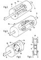
- Figure 2 is a perspective view, partially cut away, of a tube polishing unit in which polishing brushes radially contact the tubing passing therethrough;
- Figure 3 is a perspective view, partially cut away, of a further type of tubing polishing unit in which the polishing brushes tangentially contact the tubing passing therethrough;
- Figure 4 is an enlarged end view of a brush used in the unit shown in Figure 3 in contact with the tubing; and
- Figure 5 is a cut away perspective view of a buffing unit.
- In accordance with the present invention, apparatus is provided by which tubing is formed from metal strip, polished and buffed as it continuously advances along a straight-line path.
- To illustrate the invention, a line of apparatus is shown in Figure 1 in which tubing is galvanized, and the zinc coating is polished and buffed to a lustrous finish.
Metal strip 10 is unrolled fromreels 12 mounted for rotational movement on astand 14. Thestrip 10 is advanced to anend joiner unit 16 and a take-up unit 18 where strip from one reel is appropriately joined to strip from a successive reel so that the tubing may be formed as a continuous process. - The
strip 10 advances to anedge shaver 20 wherein the lateral edges of the strip are trimmed to reduce the strip to its appropriate width and to present freshly cut metal to the subsequent welding operation after the edges are brought together by the tube-formingrolls 22. - From the edge trimmer 20, the
strip 10 advances to awiper 24 to remove metal fragments and into a bank of tube-formingrolls 22. Thetubing 34 advances to aseam welder 26 to join the edges, aseam shaver 28 to scarf rough particles from the welded tubing, awater cooling spray 30, and an optional heliarc welder or any suitable type ofwelding equipment 32 to reinforce the seam and to weld any discontinuities in the seam. - The formed
tubing 34 advances to a cleaning section whereat oxide, grease, etc. are removed from the surface of the metal tubing to prepare the tubing for subsequent galvanizing. The tubing advances through astrong alkali wash 36, amedium alkali wash 38, and awater rinse 40. Thetubing 34 is pickled by a spray of acid in anacid pickling tank 42 to prepare the surface for galvanizing. Subsequently, awater rinse 44 rinses off the excess acid. - The welded and cleaned
tubing 34 then advances from the cleaning section to asteam blast 46 for further cleaning and then to aninduction heating chamber 48 to remove any remaining moisture from the surface of the tubing and to preheat the formed tubing to a temperature suitable for entry into thevat 50 of molten zinc in which the tube is galvanized. Theinduction heating unit 48 and thezinc vat 50 are maintained under an inert atmosphere to minimize oxidation. - The galvanized
tubing 34 advances through a water cool downsection 52 which cools down the tubing before it is advanced to anoptional sizing unit 54 where sizing rollers assure that thetubing 34 has its desired exterior diameter. - The sized
tubing 34 advances through atube polishing section 60 with one or more polishing units andbuffing unit 61 to provide the desired lustrous surface to the tubing. The tubing is passed through acleaner 62 where it is washed with a low alkalinity liquid cleaner and arinser 63, or the tubing may be passed through other types of cleaning apparatus where it is cleaned by solvents, ultrasound etc. The cleanedtubing 34 advances through a chromate passivatingunit 65 where the coating is rendered less chemically active. To protect the surface against subsequent oxidation, the polishedtubing 34 is thereafter passed through acoating unit 64 wherein a polymer coating is applied to the surface. After the polymer is cured or set, the polished coatedtubing 34 is advanced to a travellingshear unit 67 which cuts the tubing into its desired length. - Illustrated in Figure 2 is a
polishing unit 100 through which round galvanizedtubing 34 travels. Theunit 100 has generallycylindrical housing 102 and a plurality ofpolishing brushes 104 which are mounted from the interior wall 106 for rotation in radial contact with the surface of thetubing 34. As it is necessary that thetubing 34 be polished over the entirety of its exterior surface,brushes 104 are disposed around the path of the tubing. At a plurality of points along the path of tubing travel, apair 108 of opposedpolishing brushes 104 radially contact thetubing 34. Eachbrush 104 is mounted to press against the travelling tubing. In the apparatus illustrated in Figure 2, eachbrush 104 polishes at least a 90° arc in the tubing and a second pair 108' of brushes mounted perpendicularly thereto polish the remainder of the surface. To achieve a more uniform polished surface, it is preferred that the polishing units include additional brushes mounted at various angles around thetubing 34 to provide sufficient overlap of the arcuate polished bands.Nozzles 109 associated with at least the first fourbrushes 104 which contact thetubing 34 apply an abrasive polishing compound either directly to the tubing or to the brushes. Depending on various factors, such as the width of thebrushes 104 and their speed of rotation, it may be desirable that a plurality ofpolishing units 100 be aligned with the path of thetubing 34. The alignedpolishing units 100 preferably havebrushes 104 which provided a gradient of abrasiveness so that thetubing 34 is more finely polished in eachsuccessive polishing unit 100. - Illustrated in Figure 3 is a
polishing unit 116 having a plurality ofpolishing brushes 118 mounted around the path oftubing 34 for rotation in tangential contact therewith. As seen in Figure 4, eachbrush 118 is disc shaped with a concavearcuate polishing edge 119 substantially matched to the curvature of thetubing 34. Sufficient brushes are mounted at various angular positions relative to the tubing so that the polishing is continuous around the entire exterior surface. - Illustrated in Figure 5 is a
buffing unit 128 in which acylindrical drum 130 is lined with a plurality ofbuffing pads 132 which carry a fine abrasive such as a rouge. Each pad extends along an arcuate portion of the interior wall of the drum. Thedrum 130 is aligned in the path oftubing 34 travel and is mounted for rotation in ahousing 134 so that thepads 132 polish thetubing 34 passing therethrough. Thepads 132 contact a total of at least 240°, and preferably at least 320°, of the tubing surface at all times, and uniformly buff the surface oftubing 34 to a final highly polished finish. - Generally several polishing units are aligned with the path of tubing travel to achieve the desired lustrous finish. Typically, different types of polishing units are aligned. For example, as shown in Figure 1, the galvanized
tubing 34 may first be passed through aunit 100 of the type shown in Figure 2 in which a plurality ofbrushes 104 mounted at various angular positions relative to thetubing 34 polish the tubing with a rough abrasive. Thereafter, thetubing 34 advances through aunit 116 as shown in Figure 3 in which brushes 118 rotate in tangential contact with the tubing to polish the tubing with a finer abrasive. The reverse order, in which thetangential polishing unit 116 precedes theradial polishing unit 100, may also be employed. Theunits - The
tubing 34, emerging from the buffingsection 61 with its polished metallic coating, as a smooth, lustrous finish which in the case of zinc has the bluish-white color characteristic of freshly applied zinc. The bluish-white color of thefinished tubing 34, if exposed to the atmosphere, particularly humid atmosphere, will quickly tarnish leaving the tubing with the gray color commonly associated with galvanized tubing. As the bluish-white color of metallic zinc is generally preferable for decorative purposes to the gray of tarnished zinc, it is necessary to protect the surface from oxidation. Accordingly, the surface is coated with a suitable polymer which protects the surface. The coating cooperates with the polished metal surface to give the tubing its final surface appearance. A clear polymer may enhance the brightness of the polished coating. A transluscent coating may give the tubing a satiny finish. Died lacquers may be used to color the tubing. The polymer coating should be sufficiently durable to provide long-term protection for the zinc surface. As thetubing 34 may be later bent for forming furniture or the like, the polymer should have sufficient elasticity to fully cover the surface of the tubing even if the tubing is bent. One such suitable polymer for coating a polished galvanized surface is acrylic polyurethane. - The
polymer coating chamber 64, through which thetubing 34 is passed subsequent to polishing, is appropriate for applying the particular coating and may take the form of a bath in which the tubing is submerged in a liquid polymer coating. Preferably, however, thetubing 34 is passed through acoating unit 64 in which sprays of coating polymer are directed at the tubing to provide a generally uniform coating thereto. Electrostatic spraying may be advantageously used to apply the polymer. - Subsequent to coating, the
tubing 34 is passed through a curing unit appropriate to set the particular polymer on the tubing surface. A powder coating may be melted onto the tubing in a heating unit 170 (Figure 1). Liquid polymer coatings may be set by evaporating away the solvents in a dryingchamber 172 through which carrier gas flows. Other polymers may be cured by radiation in aunit 174 containing appropriate lamps or other sources of radiation. Various curing units may be placed on wheeled platforms for movement along atrack 188 which runs transverse to the path oftubing 34, so that the units may be alternately aligned with the path of travel of the tubing for curing alternate coatings. - The present invention adapts a line of apparatus in which galvanized tubing is continuously and inexpensively produced from strip metal, to the production of tubing having an attractive finish suitable for funiture, decorative purposes, etc. The adaption of the line of apparatus is accomplished with additional apparatus which neither significantly adds to the cost of the finished tubing nor interferes with the smooth flow of the line in which galvanized tubing is produced from strip metal. The polishing, buffing, coating and curing units are provided on-line with the tube-forming apparatus so that the efficiencies of continuous tube forming are retained.
- The attractive zinc surface provided by the line of apparatus has its own distinctive characteristics and is comparable aesthetically with commonly used ornamental metal tubing. Because the tubing is inherently cheaper to produce than commonly used tubing such as chrome plated tubing or stainless steel tubing, it is contemplated that the tubing produced by the described apparatus will be widely applicable for use in furniture, lamps, and other indoor or outdoor decorative applications. Furthermore, because the apparatus herein described provided tubing which is only slightly more expensive than tubing commonly used to form unfinished galvanized conduit tubing, it is envisioned that architectural applications will be found where it is desirable or necessary that electrical conduit remain exposed.
- The lustrous finish may optionally be provided with a brush semilustrous finish by appropriately abrading the polished tubing to form a pronounced line effect in the direction of the tubular axis.
- While for illustration purposes, apparatus has been described in which a zinc coating is applied to the tubing, other surfaces may be similarly polished and buffed to provide lustrous finishes on continuously formed tubing. Thus, the tubing may be hot dipped in other molten metals such as aluminum, aluminum alloys, tin, etc. Each different type of tubing, of course has its own requirements and the number of polishing units, the speed of the brushes, the type of abrasive etc., is adjusted accordingly.
- The tubing may have a square as well as a round configuration. Preferably polishing and buffing brushes used with square tubing will contact each edge of the tubing tangentially and have flat polishing edges.
Claims (10)
Priority Applications (1)
| Application Number | Priority Date | Filing Date | Title |
|---|---|---|---|
| AT82300304T ATE27310T1 (en) | 1981-02-09 | 1982-01-21 | CONTINUOUS PRODUCTION OF POLISHED AND BUFFERED PIPING. |
Applications Claiming Priority (2)
| Application Number | Priority Date | Filing Date | Title |
|---|---|---|---|
| US06/232,469 US4441238A (en) | 1981-02-09 | 1981-02-09 | Continuous production of polished and buffed tubing |
| US232469 | 1981-02-09 |
Publications (3)
| Publication Number | Publication Date |
|---|---|
| EP0059028A2 EP0059028A2 (en) | 1982-09-01 |
| EP0059028A3 EP0059028A3 (en) | 1982-12-29 |
| EP0059028B1 true EP0059028B1 (en) | 1987-05-20 |
Family
ID=22873242
Family Applications (1)
| Application Number | Title | Priority Date | Filing Date |
|---|---|---|---|
| EP82300304A Expired EP0059028B1 (en) | 1981-02-09 | 1982-01-21 | Continuous production of polished and buffed tubing |
Country Status (21)
| Country | Link |
|---|---|
| US (1) | US4441238A (en) |
| EP (1) | EP0059028B1 (en) |
| JP (1) | JPS57152316A (en) |
| KR (1) | KR890001368B1 (en) |
| AT (1) | ATE27310T1 (en) |
| AU (1) | AU548725B2 (en) |
| BR (1) | BR8200510A (en) |
| CA (1) | CA1179169A (en) |
| DE (1) | DE3276377D1 (en) |
| DK (1) | DK21682A (en) |
| ES (1) | ES509407A0 (en) |
| FI (1) | FI820264L (en) |
| IL (1) | IL64873A (en) |
| IN (1) | IN156042B (en) |
| MX (1) | MX157564A (en) |
| NO (1) | NO159475C (en) |
| NZ (1) | NZ199567A (en) |
| PH (1) | PH20469A (en) |
| PT (1) | PT74347B (en) |
| YU (1) | YU20982A (en) |
| ZA (1) | ZA82405B (en) |
Families Citing this family (18)
| Publication number | Priority date | Publication date | Assignee | Title |
|---|---|---|---|---|
| ZA865689B (en) * | 1985-07-31 | 1987-03-25 | Ross Leslie Palmer | Manufacture of roll formed and coated articles |
| US4621399A (en) * | 1985-12-18 | 1986-11-11 | Allied Tube & Conduit Corporation | Tube-coating method and apparatus therefor |
| USRE35879E (en) * | 1990-03-15 | 1998-08-25 | Electrostatic Technology, Inc. | Cleaning method using both wet and dry steam, and apparatus adapted therefor |
| US5116636A (en) * | 1990-03-15 | 1992-05-26 | S.L. Electrostatic Technology, Inc. | Method for steam cleaning and electrostatic coating of laminated articles |
| US5647906A (en) * | 1992-03-11 | 1997-07-15 | A-Z Terminal Corporation | Pipe cleaning machine |
| US6825418B1 (en) * | 2000-05-16 | 2004-11-30 | Wpfy, Inc. | Indicia-coded electrical cable |
| US7989028B2 (en) * | 2003-03-19 | 2011-08-02 | Allied Tube & Conduit Corporation | Continuously manufactured colored metallic products and method of manufacture of such products |
| KR100716614B1 (en) * | 2006-05-04 | 2007-05-10 | 알메탈주식회사 | Method for producing a heat roller and its product |
| EP2049300B1 (en) * | 2006-08-04 | 2010-01-06 | Rasselstein GmbH | Method for producing a corrosion-resistant, workable sheet metal with full-surface coating of the joined, thermally treated steel sheets |
| US20100266783A1 (en) * | 2009-04-15 | 2010-10-21 | Hot Dip Solutions, Llc | Method of coating a substrate |
| CN102335700A (en) * | 2010-07-16 | 2012-02-01 | 欧朋达科技(深圳)有限公司 | Metal forming method and process equipment |
| SE536078C2 (en) * | 2010-10-09 | 2013-04-30 | Core Link Ab | Device for machining sleeves |
| KR101045678B1 (en) * | 2011-05-09 | 2011-07-01 | (주)백천정밀 | Steel strip fittings applied to piping equipment |
| CN109202450A (en) * | 2018-11-05 | 2019-01-15 | 无锡华联科技集团有限公司 | Steel pipe automatically grinding cutting machine |
| DE102019005692A1 (en) * | 2019-08-14 | 2021-02-18 | Technische Universität Dortmund | Cutting edge preparation |
| CN113458940B (en) * | 2021-06-28 | 2022-12-06 | 云南省建设投资控股集团有限公司 | A scrape material auxiliary structure for reinforcing bar processing line |
| CN115502238B (en) * | 2022-10-21 | 2023-11-07 | 华鑫新材料科技(江苏)有限公司 | High-strength galvanized steel wire production equipment and production method thereof |
| CN118528141B (en) * | 2024-04-25 | 2026-01-06 | 中建三局第三建设工程有限责任公司 | A grinding unit and method for the root of metal pipe welds |
Family Cites Families (17)
| Publication number | Priority date | Publication date | Assignee | Title |
|---|---|---|---|---|
| US1056403A (en) * | 1912-07-15 | 1913-03-18 | Great Western Sugar Co | Tube cleaning and polishing apparatus. |
| US1751094A (en) * | 1928-04-06 | 1930-03-18 | F B Shuster Company | Wire-straightening machine |
| US1941002A (en) * | 1928-12-19 | 1933-12-26 | Horace L Harrison | Machine for treating pipes and the like |
| US2158400A (en) * | 1937-11-11 | 1939-05-16 | Metal Mouldings Corp | Metal forming working device |
| US2353125A (en) * | 1941-09-19 | 1944-07-11 | Arthur B Carpmail | Apparatus for cleaning pipe |
| US2680938A (en) * | 1949-11-09 | 1954-06-15 | Osborn Mfg Co | Apparatus for conditioning metal sheets and the like |
| US3122114A (en) * | 1961-05-01 | 1964-02-25 | Allied Tube & Conduit Corp | Continuous tube forming and galvanizing |
| US3230615A (en) * | 1962-11-23 | 1966-01-25 | Allied Tube & Conduit Corp | Continuous tube forming and galvanizing |
| US3559280A (en) * | 1968-03-13 | 1971-02-02 | Allied Tube & Conduit Corp | Method and apparatus for the continuous forming, galvanizing and coloring of tubing |
| US3524245A (en) * | 1968-04-11 | 1970-08-18 | Msl Tubing & Steel Co | Continuous tube forming and metallizing process |
| US3667095A (en) * | 1969-12-17 | 1972-06-06 | Allied Tube & Conduit Corp | Apparatus for coating surfaces and curing the same at high speeds |
| JPS5126150B2 (en) * | 1972-07-29 | 1976-08-04 | ||
| US3820184A (en) * | 1973-05-31 | 1974-06-28 | Raymond Lee Organization Inc | Pipe cleaning device |
| US3895463A (en) * | 1973-09-17 | 1975-07-22 | Turek & Heller Machine Inc | Metal tube buffing and polishing apparatus |
| US3889427A (en) * | 1974-04-25 | 1975-06-17 | Carando Machine Works | Metal cup abrading machine |
| JPS5177535A (en) * | 1974-12-28 | 1976-07-05 | Ishikawajima Yusoki Kk | HIMAKUJOKYO SOCHI |
| JPS56154293A (en) * | 1980-05-02 | 1981-11-28 | Nippon Kokan Kk <Nkk> | Method for repair of electric welded part of plated steel pipe |
-
1981
- 1981-02-09 US US06/232,469 patent/US4441238A/en not_active Expired - Fee Related
-
1982
- 1982-01-19 DK DK21682A patent/DK21682A/en not_active Application Discontinuation
- 1982-01-21 AT AT82300304T patent/ATE27310T1/en not_active IP Right Cessation
- 1982-01-21 EP EP82300304A patent/EP0059028B1/en not_active Expired
- 1982-01-21 ZA ZA82405A patent/ZA82405B/en unknown
- 1982-01-21 DE DE8282300304T patent/DE3276377D1/en not_active Expired
- 1982-01-22 AU AU79744/82A patent/AU548725B2/en not_active Ceased
- 1982-01-26 NZ NZ199567A patent/NZ199567A/en unknown
- 1982-01-26 IL IL64873A patent/IL64873A/en unknown
- 1982-01-27 FI FI820264A patent/FI820264L/en not_active Application Discontinuation
- 1982-01-27 PH PH26796A patent/PH20469A/en unknown
- 1982-01-28 PT PT74347A patent/PT74347B/en unknown
- 1982-01-28 IN IN110/CAL/82A patent/IN156042B/en unknown
- 1982-01-28 CA CA000395128A patent/CA1179169A/en not_active Expired
- 1982-01-29 BR BR8200510A patent/BR8200510A/en unknown
- 1982-02-01 YU YU00209/82A patent/YU20982A/en unknown
- 1982-02-08 NO NO820359A patent/NO159475C/en unknown
- 1982-02-08 ES ES509407A patent/ES509407A0/en active Granted
- 1982-02-08 KR KR8200522A patent/KR890001368B1/en not_active Expired
- 1982-02-09 JP JP57019522A patent/JPS57152316A/en active Pending
- 1982-02-09 MX MX191300A patent/MX157564A/en unknown
Non-Patent Citations (2)
| Title |
|---|
| Ullmanns Encyklopädie der Technischen Chemie, vol. 12, 1976, Verlag Chemie GmbH, Weinheim, pages 161-162 * |
| Ullmanns Encyklopädie der Technischen Chemie, vol. 15, 1978, Verlag Chemie GmbH, Weinheim, page 636 * |
Also Published As
| Publication number | Publication date |
|---|---|
| AU7974482A (en) | 1982-08-19 |
| EP0059028A2 (en) | 1982-09-01 |
| CA1179169A (en) | 1984-12-11 |
| FI820264A7 (en) | 1982-08-10 |
| AU548725B2 (en) | 1986-01-02 |
| IL64873A (en) | 1985-10-31 |
| PT74347A (en) | 1982-02-01 |
| FI820264L (en) | 1982-08-10 |
| PT74347B (en) | 1983-08-24 |
| ATE27310T1 (en) | 1987-06-15 |
| ZA82405B (en) | 1982-12-29 |
| US4441238A (en) | 1984-04-10 |
| DK21682A (en) | 1982-08-10 |
| KR890001368B1 (en) | 1989-05-02 |
| YU20982A (en) | 1985-08-31 |
| IN156042B (en) | 1985-04-27 |
| NZ199567A (en) | 1985-08-30 |
| EP0059028A3 (en) | 1982-12-29 |
| NO159475C (en) | 1989-01-04 |
| ES8301688A1 (en) | 1982-12-16 |
| ES509407A0 (en) | 1982-12-16 |
| NO820359L (en) | 1982-08-10 |
| DE3276377D1 (en) | 1987-06-25 |
| IL64873A0 (en) | 1982-03-31 |
| PH20469A (en) | 1987-01-14 |
| JPS57152316A (en) | 1982-09-20 |
| BR8200510A (en) | 1982-12-07 |
| NO159475B (en) | 1988-09-26 |
| MX157564A (en) | 1988-12-02 |
| KR830008750A (en) | 1983-12-14 |
Similar Documents
| Publication | Publication Date | Title |
|---|---|---|
| US4441238A (en) | Continuous production of polished and buffed tubing | |
| US7081168B2 (en) | Method of removing scale and inhibiting oxidation and pre-painting sheet metal | |
| US6018859A (en) | Method of forming seamed metal tube | |
| King | Surface treatment & finishing of aluminium | |
| CN1019554B (en) | Apparatus for roll forming metal articles | |
| CA1100367A (en) | One-side galvanizing | |
| US3524245A (en) | Continuous tube forming and metallizing process | |
| CA2028004C (en) | Method for producing galvanized tubing | |
| CA1132011A (en) | Process and apparatus for producing a sheet or strip which is lightly galvanized on one or both sides and products obtained by said process | |
| US3927816A (en) | Hot dipped steel tube and a method for producing the same | |
| CA1164736A (en) | Portable mechanical plater and method | |
| Davis | Surface engineering of stainless steels | |
| CA1304543C (en) | Method for galvanizing perforated steel sheet | |
| CN111593301A (en) | Method for processing whole roll of stainless steel color mirror surface anti-fingerprint film layer | |
| US3677908A (en) | Metal plating product and process | |
| JPH02185959A (en) | Production of hot dip galvanized steel sheet having superior vividness | |
| CZ78699A3 (en) | Method of surface treatment of workpieces | |
| US3596012A (en) | Apparatus for the production of electrolytic tinplate | |
| CN110732808A (en) | Production and manufacturing process of copper-plating-free gas shielded welding wires | |
| TH751A (en) | The machine produces a continuously polished and honed pipe. | |
| TH846B (en) | The machine produces a continuously polished and honed pipe. | |
| Steel | Enclosure for Painting and Enforcing Evaporation US PaleM5, 397,606. Mr. 14, 1995 | |
| US10294571B2 (en) | Coloration of electroless nickel plating by application of cold bluing solutions | |
| JPH0327803A (en) | Temper rolling device and rolling method for galvanized steel strip | |
| JP2004066265A (en) | Method for manufacturing metal plated steel tube |
Legal Events
| Date | Code | Title | Description |
|---|---|---|---|
| ITTA | It: last paid annual fee | ||
| PUAI | Public reference made under article 153(3) epc to a published international application that has entered the european phase |
Free format text: ORIGINAL CODE: 0009012 |
|
| AK | Designated contracting states |
Designated state(s): AT BE CH DE FR GB IT LU NL SE |
|
| PUAL | Search report despatched |
Free format text: ORIGINAL CODE: 0009013 |
|
| AK | Designated contracting states |
Designated state(s): AT BE CH DE FR GB IT LI LU NL SE |
|
| 17P | Request for examination filed |
Effective date: 19830620 |
|
| ITF | It: translation for a ep patent filed | ||
| GRAA | (expected) grant |
Free format text: ORIGINAL CODE: 0009210 |
|
| AK | Designated contracting states |
Kind code of ref document: B1 Designated state(s): AT BE CH DE FR GB IT LI LU NL SE |
|
| REF | Corresponds to: |
Ref document number: 27310 Country of ref document: AT Date of ref document: 19870615 Kind code of ref document: T |
|
| REF | Corresponds to: |
Ref document number: 3276377 Country of ref document: DE Date of ref document: 19870625 |
|
| ET | Fr: translation filed | ||
| PG25 | Lapsed in a contracting state [announced via postgrant information from national office to epo] |
Ref country code: LU Free format text: LAPSE BECAUSE OF NON-PAYMENT OF DUE FEES Effective date: 19880131 |
|
| PLBE | No opposition filed within time limit |
Free format text: ORIGINAL CODE: 0009261 |
|
| STAA | Information on the status of an ep patent application or granted ep patent |
Free format text: STATUS: NO OPPOSITION FILED WITHIN TIME LIMIT |
|
| 26N | No opposition filed | ||
| PGFP | Annual fee paid to national office [announced via postgrant information from national office to epo] |
Ref country code: FR Payment date: 19881230 Year of fee payment: 8 |
|
| PGFP | Annual fee paid to national office [announced via postgrant information from national office to epo] |
Ref country code: CH Payment date: 19890109 Year of fee payment: 8 |
|
| PGFP | Annual fee paid to national office [announced via postgrant information from national office to epo] |
Ref country code: SE Payment date: 19890131 Year of fee payment: 8 Ref country code: NL Payment date: 19890131 Year of fee payment: 12 |
|
| PGFP | Annual fee paid to national office [announced via postgrant information from national office to epo] |
Ref country code: DE Payment date: 19890206 Year of fee payment: 8 |
|
| PGFP | Annual fee paid to national office [announced via postgrant information from national office to epo] |
Ref country code: AT Payment date: 19900104 Year of fee payment: 9 |
|
| PGFP | Annual fee paid to national office [announced via postgrant information from national office to epo] |
Ref country code: BE Payment date: 19900112 Year of fee payment: 9 |
|
| PG25 | Lapsed in a contracting state [announced via postgrant information from national office to epo] |
Ref country code: SE Effective date: 19900122 |
|
| PG25 | Lapsed in a contracting state [announced via postgrant information from national office to epo] |
Ref country code: LI Effective date: 19900131 Ref country code: CH Effective date: 19900131 |
|
| PGFP | Annual fee paid to national office [announced via postgrant information from national office to epo] |
Ref country code: GB Payment date: 19900131 Year of fee payment: 9 |
|
| PG25 | Lapsed in a contracting state [announced via postgrant information from national office to epo] |
Ref country code: FR Effective date: 19900928 |
|
| REG | Reference to a national code |
Ref country code: CH Ref legal event code: PL |
|
| PG25 | Lapsed in a contracting state [announced via postgrant information from national office to epo] |
Ref country code: DE Effective date: 19901002 |
|
| REG | Reference to a national code |
Ref country code: FR Ref legal event code: ST |
|
| PG25 | Lapsed in a contracting state [announced via postgrant information from national office to epo] |
Ref country code: GB Effective date: 19910121 Ref country code: AT Effective date: 19910121 |
|
| PG25 | Lapsed in a contracting state [announced via postgrant information from national office to epo] |
Ref country code: BE Effective date: 19910131 |
|
| PG25 | Lapsed in a contracting state [announced via postgrant information from national office to epo] |
Ref country code: NL Effective date: 19910801 |
|
| NLV4 | Nl: lapsed or anulled due to non-payment of the annual fee | ||
| GBPC | Gb: european patent ceased through non-payment of renewal fee | ||
| EUG | Se: european patent has lapsed |
Ref document number: 82300304.1 Effective date: 19901106 |