EP0058801A1 - Appareil de mesure utilisant des techniques d'interférence optique - Google Patents
Appareil de mesure utilisant des techniques d'interférence optique Download PDFInfo
- Publication number
- EP0058801A1 EP0058801A1 EP81305534A EP81305534A EP0058801A1 EP 0058801 A1 EP0058801 A1 EP 0058801A1 EP 81305534 A EP81305534 A EP 81305534A EP 81305534 A EP81305534 A EP 81305534A EP 0058801 A1 EP0058801 A1 EP 0058801A1
- Authority
- EP
- European Patent Office
- Prior art keywords
- interferometer
- frequency
- source
- light
- bandwidth
- Prior art date
- Legal status (The legal status is an assumption and is not a legal conclusion. Google has not performed a legal analysis and makes no representation as to the accuracy of the status listed.)
- Granted
Links
- 230000003287 optical effect Effects 0.000 title description 12
- 238000000034 method Methods 0.000 title description 2
- 230000005540 biological transmission Effects 0.000 claims abstract description 10
- 239000000126 substance Substances 0.000 claims abstract description 7
- 238000010009 beating Methods 0.000 claims abstract description 6
- 230000035559 beat frequency Effects 0.000 claims description 17
- 239000003054 catalyst Substances 0.000 claims description 17
- 230000003595 spectral effect Effects 0.000 claims description 10
- 239000012530 fluid Substances 0.000 claims description 9
- 238000010521 absorption reaction Methods 0.000 claims description 6
- 238000001514 detection method Methods 0.000 claims description 6
- 239000007787 solid Substances 0.000 claims description 5
- 238000011144 upstream manufacturing Methods 0.000 claims description 2
- 230000001427 coherent effect Effects 0.000 abstract description 4
- 239000007789 gas Substances 0.000 description 41
- 230000005855 radiation Effects 0.000 description 14
- 230000008859 change Effects 0.000 description 11
- 239000013307 optical fiber Substances 0.000 description 10
- 238000002310 reflectometry Methods 0.000 description 6
- 239000000835 fiber Substances 0.000 description 5
- 238000005259 measurement Methods 0.000 description 4
- 239000000523 sample Substances 0.000 description 4
- BJQHLKABXJIVAM-UHFFFAOYSA-N bis(2-ethylhexyl) phthalate Chemical compound CCCCC(CC)COC(=O)C1=CC=CC=C1C(=O)OCC(CC)CCCC BJQHLKABXJIVAM-UHFFFAOYSA-N 0.000 description 3
- 238000006243 chemical reaction Methods 0.000 description 3
- 238000001228 spectrum Methods 0.000 description 3
- QVGXLLKOCUKJST-UHFFFAOYSA-N atomic oxygen Chemical compound [O] QVGXLLKOCUKJST-UHFFFAOYSA-N 0.000 description 2
- 238000002485 combustion reaction Methods 0.000 description 2
- 230000000694 effects Effects 0.000 description 2
- 239000001301 oxygen Substances 0.000 description 2
- 229910052760 oxygen Inorganic materials 0.000 description 2
- 230000009467 reduction Effects 0.000 description 2
- 239000013074 reference sample Substances 0.000 description 2
- 230000004304 visual acuity Effects 0.000 description 2
- 241000196324 Embryophyta Species 0.000 description 1
- 244000256297 Euphorbia tirucalli Species 0.000 description 1
- 230000002238 attenuated effect Effects 0.000 description 1
- 230000008901 benefit Effects 0.000 description 1
- 230000015572 biosynthetic process Effects 0.000 description 1
- 238000010276 construction Methods 0.000 description 1
- 238000011109 contamination Methods 0.000 description 1
- 230000000977 initiatory effect Effects 0.000 description 1
- 239000000463 material Substances 0.000 description 1
- 238000012544 monitoring process Methods 0.000 description 1
- 238000004886 process control Methods 0.000 description 1
- 230000009257 reactivity Effects 0.000 description 1
- 230000035945 sensitivity Effects 0.000 description 1
- 238000000926 separation method Methods 0.000 description 1
- 239000002341 toxic gas Substances 0.000 description 1
- 230000001960 triggered effect Effects 0.000 description 1
- 230000000007 visual effect Effects 0.000 description 1
Images


Classifications
-
- G—PHYSICS
- G01—MEASURING; TESTING
- G01N—INVESTIGATING OR ANALYSING MATERIALS BY DETERMINING THEIR CHEMICAL OR PHYSICAL PROPERTIES
- G01N21/00—Investigating or analysing materials by the use of optical means, i.e. using sub-millimetre waves, infrared, visible or ultraviolet light
- G01N21/17—Systems in which incident light is modified in accordance with the properties of the material investigated
- G01N21/41—Refractivity; Phase-affecting properties, e.g. optical path length
- G01N21/45—Refractivity; Phase-affecting properties, e.g. optical path length using interferometric methods; using Schlieren methods
-
- G—PHYSICS
- G01—MEASURING; TESTING
- G01J—MEASUREMENT OF INTENSITY, VELOCITY, SPECTRAL CONTENT, POLARISATION, PHASE OR PULSE CHARACTERISTICS OF INFRARED, VISIBLE OR ULTRAVIOLET LIGHT; COLORIMETRY; RADIATION PYROMETRY
- G01J9/00—Measuring optical phase difference; Determining degree of coherence; Measuring optical wavelength
- G01J9/04—Measuring optical phase difference; Determining degree of coherence; Measuring optical wavelength by beating two waves of a same source but of different frequency and measuring the phase shift of the lower frequency obtained
Definitions
- This invention relates to apparatus for measuring or detecting changes in physical or chemical parameters using optical interference techniques.
- an apparatus for measuring or detecting changes in a physical or chemical parameter comprises a light source, an interferometer having variable interference means positioned to receive light from the source and to transmit a portion of that light at a discrete frequency which is variable over a range of frequencies within the source bandwidth, means for applying the parameter to the interference means thereby to vary the transmission frequency as a function of changes in the parameter, means for beating the transmitted frequency with a reference frequency taken coherently from the same light source, and detection means for measuring or detecting changes in the beat frequency thereby produced.
- the light source may cover a finite bandwidth anywhere within that portion of the spectrum which is readily transmitted by optical fibres. At present optical fibres can be obtained which can transmit all the visible light, the near ultra-violet, and extend well into the infra-red. As will be realised, the light source bandwidth must be substantially broader than the resolution of the interferometer in order that the latter may provide a range of transmitted frequencies within that bandwidth. On the other hand, where the source bandwidth is greater than the spectral range of the interferometer, more than one discrete frequency may be transmitted, leading to a plurality of beat frequencies. This makes complex analysis of the beats necessary, and loses much of the simplicity of operation which is otherwise possible.
- the spectral range of an interferometer is the separation of any two transmitted frequencies differing by one order of interference, i.e. the spectral range is the maximum value of 8v which is sufficiently small for the nth order of interference at frequency ⁇ not to overlap with the (n + l)th order of interference at frequency (v + ôv).
- a preferred apparatus is one wherein the total bandwidth of light reaching the detector after passing through the interferometer, is equal to or less than the spectral range of the interferometer, thereby to produce only a single beat frequency at a time.
- the bandwidth can be restricted by passing the beam through filters of the appropriate bandwidth.
- it is generally preferred to restrict the bandwidth at source such as by using a source which does itself emit light having a bandwidth equal to or less than the spectral bandwidth of the interferometer.
- Suitable light sources include gas lasers and laser diodes which fall within the above criteria. Some of these may also produce light at frequencies other than their dominant frequencies, but at much lower intensities.
- any beat frequency due to these stray lines will generally be so high as to be undetected.
- the preferred interferometer is a Fabry-Perot interferometer comprising partially reflective parallel layers separated by a transparent spacing layer whose refractive index or thickness is variable with variation in the parameter to be measured.
- the resolving power depends on the reflectivity of the reflective layers. The greater the reflectivity, the greater is the resolving power, (and'hence the narrower may be the source'bandwidth) and hence the accuracy of the frequency shift measurement; but this can only be achieved with a reduction in the intensity' of the transmitted radiation.
- the spectral range of a Fabry-Perot interferometer is given by the formula: where p is the refractive index and t is the thickness of the spacing layer.
- the parameter to be measured is applied to the interferometer so as to vary the thickness or refractive index of the spacing layer as a function of variations in the parameter. While varying one of those two variables in the interferometer, the other may of course be varied at the same time either intentionally or because it is unavoidable, the overall effect of which may be enhancement or reduction of the effect due to only one of the variables.
- the spacing layer may be a transparent solid block with parallel faces coated to provide the partially reflective layers. Changes in temperature or pressure may vary the optical path length and hence cause a change in the transmission frequency.
- a hollow block may be used in a similar manner but the relative contributions of changes in refractive index and thickness respectively with changes in the applied parameter, will generally be different from those of a solid block.
- a more generally versatile interferometer is one in which the spacing layer is a hollow cell with means for introducing and removing a fluid. This may be used for measuring such parameters as temperature, pressure and chemical composition by using a fluid whose refractive index can change with changes in such parameters.
- the interferometer may be one wherein the hollow cell is connected to the reflective layers such that variations in the pressure of fluid in the cell cause variations in the spacing of the reflective layers. This may be used to measure not only pressure, but indirectly other parameters also, where such parameters (e.g. temperature) may be used to vary the pressure of the fluid in the cell.
- the apparatus may be used simply for detecting a change in a parameter, and operating an alarm or initiating a further series of events when such a change is detected.
- an effluent gas stream may be monitored for the presence of a particular poison gas having a different refractive index or behaving differently to a selective catalyst as described in more detail hereinafter.
- simple detection bf a change in beat frequency from a norm by a predetermined amount, may be all that is required.
- the apparatus can readily be adapted for the measurement or detection of changes in a wide variety of physical and chemical parameters. No electrical power is required at its point of measurement and its ability to use fibre optics for communicating with distant control centres enables inherently safe process control to be achieved. As such it is particularly advantageous in petroleum plants and other flame-free hazard areas. It is also useful in enabling information to be obtained, free from electrical interference.
- the apparatus is particularly useful for monitoring a gas stream for the presence of a specific gas which is reactable in the presence of a catalyst with the evolution or absorption of heat.
- the apparatus is adapted for this use by employing an interferometer which is sensitive to changes in temperature, and locating it in thermal contact with a mass of the catalyst, so that in turn it becomes sensitive to any specific gas changing the temperature on meeting the catalyst.
- the sensitive interferometer with its catalyst being located within the conduit, the conduit also being; provided with a reference interferometer upstream of the sensitive interferometer wherein the reference interferometer is substantially the same as the sensitive interferometer except that it is not in contact with any of the catalyst.
- Light from the source is then supplied separately to each interferometer, and their transmitted portions thereafter combined to produce the beats.
- the rference interferometer in this application of the apparatus not only provides a narrow frequency band to give strong beats, but it also reacts to changes in ambient temperatures and changes in the temperature of the gas stream being supplied to the conduit, in essentially the same manner as the sensitive interferometer. Hence the beat frequencies remain substantially unchanged by such extraneous temperature changes.
- the apparatus is not, however, restricted to remote sensing applications, and can, in fact, also provide a range of self-contained analytical sensors having a variety of laboratory and chemical plant uses.
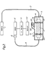
- a light source 1 emits radiation which is transmitted by an optical fibre 2 to an interferometer 3.
- Light emerging from the interferometer is focussed onto one end of an optical fibre 4 which carries it towards a photodiode 5, onto which it is focussed by a lens 6.
- a reference sample of light from the source passes through a filter 7 and is carried by a further optical fibre 8, to be focussed onto the photodiode by the same lens 6 as that used for the light from the interferometer, in such a way as to maximise overlap.
- the two optical paths are provided with additional elements (not shown) as necessary to maintain coherency of the two samples of light being focussed together onto the diode.
- the latter is connected electrically to a frequency meter 9 and thence to a display 10.
- the interferometer 3 is of the Fabry Perot type, comprising a solid block 11 having parallel end faces 12 coated to about 95% reflectivity. This is mounted in a case 13 having windows and collimating lenses 14 to direct incoming light from one optical fibre 2 onto the interferometer, and to focus the emerging light onto the other adjacent fibre 4 for transmission to the diode.
- the case is let into a pipe 15 through which travels the gas whose temperature is to be measured, and the block is supported in the case by bulkheads 16 which form a gas- tight seal between the block and the case.
- the various samples of light travelling along the optical fibres during operation of the apparatus have different intensity profiles with frequency. These are sketched graphically adjacent to the optical-fibres to which they relate.
- light travelling along the optical fibre 2 interconnecting the source 1 and interferometer 3 has a finite bandwidth v l -v 2 .
- the light is multiply reflected within the block 11 and emerges along the axis as a single discrete frequency v x which lies within the band v l -v 2 .
- the bandwidth of the emerging light is a function of the reflectivity of the coated end faces and the length of the etalon.
- the faces have been given high reflectivity to obtain an emergent light which is substantially monochromatic by comparison with the source radiation. This is obtained at the expense of intensity and the filter 7 is designed to provide a reference beam which is not only substantially monochromatic, with a frequency of v o , but which is also attenuated to approximately the same intensity as the light emerging from the interferometer.
- the transmitted light is combined with the reference sample on the surface of the photodiode and, being coherent, they interfere. They are, however, very close in frequency and so produce a beat frequency which is sufficiently slow to be resolved by the photodiode.
- the rate of beating is then-measured electronically by the frequency meter and the result made accessible by a visual display unit 10.
- This display unit could equally well be a pen and chart recorder or a digital display, or indeed may be replaced by or include, feed back to adjust the temperature control when the temperature varies from a preset value by an unacceptable amount.
- a laser source 1 emits radiation having a bandwidth of (v 2 - v l ), which is carried along an optical fibre 2 to an interferometer 3. It is then collimated onto a solid transparent block 11, and the axial emergent radiation is focussed onto a second optical fibre 4 which carries it to a photodiode 5. Output from the diode goes to a frequency meter 9 and thence to a display 10.
- This example does differ from the previous, however, in that no further sample of the source radiation is provided separately. Instead, only a portion 21 of the inlet end of the block is reflectively coated with a corresponding portion 22 of the exit end. likewise coated. Around the coated position of the exit end is also provided an annular transmission filter 23.
- the central portion of the block transmits at a discrete frequency v x while the surrounding annulus transmits at a frequency of v o , the areas being adjusted such that the transmitted frequencies emerge at a similar order of magnitude.
- These are focussed by a lens 14 onto the end of the second optical fibre 4, such lens being preferably of graded index rod construction. Being coherent, they will beat as before, but in this case the sample and reference frequencies are combined before being carried along the second optical fibre to the diode. This ensures that they are combined within the coherence length of the radiation without any need for additional fibre lengths or delay loops.
- the apparatus of Figure 3 was designed to detect in a stream of oxygen, gases combustible in the presence of a catalyst; but it is equally applicable to the detection of other gases which react or decompose spontaneously in the presence of a catalyst, with the evolution or absorption of heat.
- the optics of this apparatus consist essentially of a light source 31, a Fabry Perot interferometer 32 comprising a transparent hollow block 33 partially coated on its internal parallel end faces 34 to a reflectivity of about 95% for each face, a photodiode 35, optical fibres 36, for carrying the light from the source to the interferometer and thence to the diode via lens systems37 and a bypass fibre 38 carrying an interference filter 39 of pass frequency v o .
- the interferometer is enclosed in a case 40 having inlet and outlet through which gas can flow, and a porous mass of catalyst 41 is located around the transparent block. Output from the diode is fed to an alarm 43 via a comparator 44 connected to a reference 45.
- gas oxygen
- the reference 45 is then set to the same frequency as the beat frequency.
- FIG 3 The embodiment of Figure 3 is difficult to use for detecting small quantities of combustible gases, as temperature variations in the ingoing gas stream can mask any small temperature rise due to combustion.
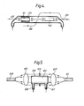
- two similar Fabry-Perot interferometers 51, 52 are placed in the gas stream, one 51 being coated with catalyst 53, the other not. These are shown in close tandem formation, but that need not be so provided both are in temperature equilibrium with the gas, and provided that the heat generated by reaction in the vicinity of the catalyst does not affect the temperature of the reference interferometer 52.
- Light from a source (not shown) is piped into the system via an optical fibre to a Y junction 54, where it is divided into two roughly equal portions. These are directed onto the two interferometers, one portion each, by collimating lenses.
- the radiation emerging from'the two interferometers is focussed onto two equal optical fibres 55, 56 to be carried away, combined and applied as a beat frequency to a photodiode or other detector, substantially as shown in Figure 1.
- the emerging frequencies will be the same when no reaction takes place on the catalyst.
- the two emerging frequencies need not be identical, although they do need to be sufficiently'close to fall within the bandwidth of the source and to produce a beat frequency measurable by the detector used.
- measurement of the change in the beat frequency gives a measure of the amount of combustible gas in the carrier stream.
- the two interferometers are equally affected, and the beat frequency should not change on that account.
- the apparatus shownin in Figure 5 was designed as a lightweight portable gas detector, which could be connected into a gas stream or sample the atmosphere, to detect certain gases or to measure their concentration. It has a source 61 producing radiation which is divided, part going through an interferometer 62 and the remainder bypassing the interferometer, either by simply passing around the interferometer as shown, or by following a separate guided path. In both cases this remainder passes through a stable filter 63 to provide a constant reference frequency. Both the transmitted beam and the reference beam are received on the surface of a frequency responsive detector 64 to provide a beat frequency in like manner to the previous example, the optical system again consisting essentially of lenses 65 for collimating and focussing the radiation respectively.
- the interferometer consists of a hollow cell 66 having inlet 67 and outlet 68 for connection to external equipment containing the gas to be analysed, or it may be provided with a simple metering pump when its purpose is to sample the air.
- the present apparatus of Figure 5 uses a change of refractive index when the appropriate gas is present. This makes use of the very rapid variation in refractive index adjacent to a resonant frequency of the gas molecules, and the length of the cell is selected such that its transmission frequency corresponds to an absorption frequency of the gas to be detected, with the source frequency band spanning the absorption frequency.
- the cells may be specifically designed for a particular gas, or a tuneable etalon may be used. Radiation bands within the near infra-red provide absorption frequencies for most gases.
- beating might be obtainable in Figures 2 and 5 without the provision of a filter for sharpening the reference frequency (v o ), when the intensities are adjusted (e.g. by attenuators or by using suitable transmissive areas) to be at least approximately the same.
- a sharply defined reference frequency as indicated in Figure 1, and to produce this by passing a portion of the light from the source through a stable Fabry-Perot device or other stable interference filter which transmits at a frequency within the source bandwidth.
- This also has an advantage in that the selected reference frequency can be to one edge of the source waveband, thereby maximising the spread of frequencies which can be used effectively by the variable interferometer.
- each of the specific embodiments shown in the drawings is a combination of several different features for most of which there are a number of alternatives.
- the specific embodiments have therefore been selected so as to illustrate as many of the more useful alternatives as possible in a reasonably small number of examples.
- Many of individual features are, however, interchangeable and may be selected to suit specific requirements.
- the embodiment shown in Figure 5 may be adapted for remote analysis or detection by incorporating fibre optics as shown in one of the other drawings.
- the interferometer of Figure 1 may have a hollow etalon as shown in Figure 3 to reduce its thermal mass, or a separate reference beam as shown in Figure 1 may be used in the apparatus of Figure 2 where particularly high pressures require such strong cases that passage of reference radiation through the apparatus becomes difficult to achieve.
Landscapes
- Physics & Mathematics (AREA)
- Spectroscopy & Molecular Physics (AREA)
- General Physics & Mathematics (AREA)
- Health & Medical Sciences (AREA)
- Life Sciences & Earth Sciences (AREA)
- Chemical & Material Sciences (AREA)
- Analytical Chemistry (AREA)
- Biochemistry (AREA)
- General Health & Medical Sciences (AREA)
- Immunology (AREA)
- Pathology (AREA)
- Investigating Or Analysing Materials By Optical Means (AREA)
- Length Measuring Devices By Optical Means (AREA)
- Arrangements For Transmission Of Measured Signals (AREA)
- Optical Transform (AREA)
- Instruments For Measurement Of Length By Optical Means (AREA)
Priority Applications (1)
| Application Number | Priority Date | Filing Date | Title |
|---|---|---|---|
| AT81305534T ATE25430T1 (de) | 1980-12-17 | 1981-11-24 | Messapparat mit verwendung optischer interferenztechnik. |
Applications Claiming Priority (2)
| Application Number | Priority Date | Filing Date | Title |
|---|---|---|---|
| GB8040393 | 1980-12-17 | ||
| GB8040393 | 1980-12-17 |
Publications (2)
| Publication Number | Publication Date |
|---|---|
| EP0058801A1 true EP0058801A1 (fr) | 1982-09-01 |
| EP0058801B1 EP0058801B1 (fr) | 1987-02-04 |
Family
ID=10518034
Family Applications (1)
| Application Number | Title | Priority Date | Filing Date |
|---|---|---|---|
| EP81305534A Expired EP0058801B1 (fr) | 1980-12-17 | 1981-11-24 | Appareil de mesure utilisant des techniques d'interférence optique |
Country Status (5)
| Country | Link |
|---|---|
| US (1) | US4417815A (fr) |
| EP (1) | EP0058801B1 (fr) |
| JP (1) | JPS57134798A (fr) |
| AT (1) | ATE25430T1 (fr) |
| DE (1) | DE3175909D1 (fr) |
Cited By (5)
| Publication number | Priority date | Publication date | Assignee | Title |
|---|---|---|---|---|
| EP0172623A2 (fr) * | 1984-07-06 | 1986-02-26 | Metricor, Inc. | Dispositif de mesure optique utilisant un capteur à modulation spectrale ayant une structure optique résonnante |
| GB2182433A (en) * | 1985-11-02 | 1987-05-13 | Stc Plc | Remote sensor |
| US4945230A (en) * | 1984-07-06 | 1990-07-31 | Metricor, Inc. | Optical measuring device using a spectral modulation sensor having an optically resonant structure |
| WO1991016597A1 (fr) * | 1990-04-23 | 1991-10-31 | Commonwealth Scientific And Industrial Research Organisation | Systeme et procedes interferometriques |
| AU658824B2 (en) * | 1990-04-23 | 1995-05-04 | Commonwealth Scientific And Industrial Research Organisation | Interferometry systems and methods |
Families Citing this family (9)
| Publication number | Priority date | Publication date | Assignee | Title |
|---|---|---|---|---|
| US4533249A (en) * | 1982-09-30 | 1985-08-06 | Honeywell Inc. | Passive ring resonator angular rate sensor |
| US4856899A (en) * | 1985-12-20 | 1989-08-15 | Yokogawa Electric Corporation | Optical frequency analyzer using a local oscillator heterodyne detection of incident light |
| DE3820170A1 (de) * | 1988-06-14 | 1989-12-21 | Messerschmitt Boelkow Blohm | Messgeber zur messung physikalischer groessen |
| FR2634560B1 (fr) * | 1988-07-19 | 1990-11-30 | France Etat Armement | Systemes de mesure electro-optiques pour l'analyse frequentielle de signaux a tres large bande |
| US5917966A (en) * | 1995-12-14 | 1999-06-29 | Motorola Inc. | Interferometric optical chemical sensor |
| US20080297808A1 (en) * | 2005-12-06 | 2008-12-04 | Nabeel Agha Riza | Optical Sensor For Extreme Environments |
| US7852490B2 (en) * | 2007-02-05 | 2010-12-14 | Palo Alto Research Center Incorporated | Implanting optical cavity structures |
| WO2010008789A2 (fr) * | 2008-06-23 | 2010-01-21 | University Of South Florida | Réseau de capteurs chimiques interférométriques |
| CN109444079B (zh) * | 2018-12-12 | 2023-08-01 | 中国计量大学 | 一种光纤测氧气传感器 |
Citations (4)
| Publication number | Priority date | Publication date | Assignee | Title |
|---|---|---|---|---|
| US3551051A (en) * | 1967-08-18 | 1970-12-29 | Gen Electrodynamics Corp | Infra-red detectors |
| US3915573A (en) * | 1973-02-08 | 1975-10-28 | Hewlett Packard Gmbh | Variable-frequency interferometer resonance filter |
| US3939348A (en) * | 1974-06-11 | 1976-02-17 | Allied Chemical Corporation | Infrared gas analysis |
| EP0013974A1 (fr) * | 1979-01-22 | 1980-08-06 | Rockwell International Corporation | Procédé et dispositif pour un capteur à franges Fabrey-Perot à rayons multiples |
Family Cites Families (1)
| Publication number | Priority date | Publication date | Assignee | Title |
|---|---|---|---|---|
| US4355898A (en) * | 1979-05-23 | 1982-10-26 | Plessey Overseas Limited | Optical detecting, monitoring or measuring arrangements |
-
1981
- 1981-11-24 DE DE8181305534T patent/DE3175909D1/de not_active Expired
- 1981-11-24 EP EP81305534A patent/EP0058801B1/fr not_active Expired
- 1981-11-24 AT AT81305534T patent/ATE25430T1/de not_active IP Right Cessation
- 1981-12-08 US US06/328,710 patent/US4417815A/en not_active Expired - Fee Related
- 1981-12-17 JP JP56204506A patent/JPS57134798A/ja active Pending
Patent Citations (4)
| Publication number | Priority date | Publication date | Assignee | Title |
|---|---|---|---|---|
| US3551051A (en) * | 1967-08-18 | 1970-12-29 | Gen Electrodynamics Corp | Infra-red detectors |
| US3915573A (en) * | 1973-02-08 | 1975-10-28 | Hewlett Packard Gmbh | Variable-frequency interferometer resonance filter |
| US3939348A (en) * | 1974-06-11 | 1976-02-17 | Allied Chemical Corporation | Infrared gas analysis |
| EP0013974A1 (fr) * | 1979-01-22 | 1980-08-06 | Rockwell International Corporation | Procédé et dispositif pour un capteur à franges Fabrey-Perot à rayons multiples |
Non-Patent Citations (4)
| Title |
|---|
| APPLIED OPTICS, vol. 15, no. 11, pages 2645-2648, November 1976, New York (USA); * |
| APPLIED OPTICS, vol. 6, no. 6, June 1967, New York (USA); * |
| APPLIED OPTICS, vol. 9, no. 11, page 2477-2480, November 1970, New York (USA). * |
| JOURNAL OF PHYSICS D: APPLIED PHYSICS, vol. 11, 1978, pages 313-323, London (GB) * |
Cited By (13)
| Publication number | Priority date | Publication date | Assignee | Title |
|---|---|---|---|---|
| EP0423903A2 (fr) * | 1984-07-06 | 1991-04-24 | Photonetics, Inc. | Capteur à modulation spectrale avec une structure de résonance optique et dispositif de mesure optique utilisant ce capteur |
| EP0172623A3 (en) * | 1984-07-06 | 1986-08-20 | Technology Dynamics Inc | Optical measuring device using a spectral modulation sensor having an optically resonant structure |
| US4678904A (en) * | 1984-07-06 | 1987-07-07 | Technology Dynamics, Inc. | Optical measuring device using a spectral modulation sensor having an optically resonant structure |
| US4945230A (en) * | 1984-07-06 | 1990-07-31 | Metricor, Inc. | Optical measuring device using a spectral modulation sensor having an optically resonant structure |
| EP0172623A2 (fr) * | 1984-07-06 | 1986-02-26 | Metricor, Inc. | Dispositif de mesure optique utilisant un capteur à modulation spectrale ayant une structure optique résonnante |
| EP0423903A3 (en) * | 1984-07-06 | 1991-07-17 | Metricor, Inc. | Optical measuring device using a spectral modulation sensor having an optically resonant structure |
| EP0665425A2 (fr) * | 1984-07-06 | 1995-08-02 | Photonetics, Inc. | Senseur de modulation spectrale |
| EP0665425A3 (fr) * | 1984-07-06 | 1995-11-02 | Photonetics Inc | Senseur de modulation spectrale. |
| GB2182433A (en) * | 1985-11-02 | 1987-05-13 | Stc Plc | Remote sensor |
| GB2182433B (en) * | 1985-11-02 | 1989-10-25 | Stc Plc | Remote sensor |
| WO1991016597A1 (fr) * | 1990-04-23 | 1991-10-31 | Commonwealth Scientific And Industrial Research Organisation | Systeme et procedes interferometriques |
| AU658824B2 (en) * | 1990-04-23 | 1995-05-04 | Commonwealth Scientific And Industrial Research Organisation | Interferometry systems and methods |
| US5617207A (en) * | 1990-04-23 | 1997-04-01 | Commonwealth Scientific And Industrial Research Organisation | Appartatus and method for measuring a change in an energy path length |
Also Published As
| Publication number | Publication date |
|---|---|
| JPS57134798A (en) | 1982-08-20 |
| EP0058801B1 (fr) | 1987-02-04 |
| ATE25430T1 (de) | 1987-02-15 |
| US4417815A (en) | 1983-11-29 |
| DE3175909D1 (en) | 1987-03-12 |
Similar Documents
| Publication | Publication Date | Title |
|---|---|---|
| US4417815A (en) | Measuring apparatus | |
| US4081215A (en) | Stable two-channel, single-filter spectrometer | |
| US9784674B2 (en) | Analytes monitoring by differential swept wavelength absorption spectroscopy methods | |
| US8049881B2 (en) | Optical analysis system and methods for operating multivariate optical elements in a normal incidence orientation | |
| CA2086338C (fr) | Procede et dispositif pour determiner des quantites mesurees au moyen d'un module a capteur optique integre | |
| Goody | Cross-correlating spectrometer | |
| CA1287234C (fr) | Thermometrie | |
| US4371785A (en) | Method and apparatus for detection and analysis of fluids | |
| US3997786A (en) | System for spectroscopic analysis of a chemical stream | |
| KR950033445A (ko) | 광학섬유를 사용하는 온도측정방법과 기구 | |
| US4647777A (en) | Selective gas detector | |
| US4430565A (en) | Correlating fiber optical measuring device | |
| GB2163251A (en) | Infrared gas detector | |
| IT9019721A1 (it) | Apparecchiatura per la rilevazione di gas a laser infrarosso e fibre ottiche | |
| JPS6189543A (ja) | デユアルビームスペクトル透過率の測定方法及び装置 | |
| Hollowell | Current instrumentation for continuous monitoring for SO2 | |
| US4733084A (en) | Method of detection and quantitative determination of sulfur and sulfur monitor using the method | |
| CN104949937A (zh) | 基于光纤光栅微腔的相移光纤光栅氢气传感器 | |
| Dakin | Review of fibre optic gas sensors | |
| US7675616B1 (en) | Combustion plume absorption gauge | |
| Thusitha | Process monitor for an ammoniacal nickel solution employing an infrared light-emitting diode and a log-ratio amplifier | |
| Norris | Optical fiber chemical sensors: Fundamentals and applications | |
| US20230213439A1 (en) | System and Method of Measuring Contaminants in a Substantially Translucent Material, Such as Water | |
| McIvor | On-Line Applications Of Infrared Spectroscopy In The Chemical Industry | |
| JPS56137236A (en) | Measuring device for temperature |
Legal Events
| Date | Code | Title | Description |
|---|---|---|---|
| PUAI | Public reference made under article 153(3) epc to a published international application that has entered the european phase |
Free format text: ORIGINAL CODE: 0009012 |
|
| AK | Designated contracting states |
Designated state(s): AT BE CH DE FR GB LI NL SE |
|
| 17P | Request for examination filed |
Effective date: 19821126 |
|
| GRAA | (expected) grant |
Free format text: ORIGINAL CODE: 0009210 |
|
| AK | Designated contracting states |
Kind code of ref document: B1 Designated state(s): AT BE CH DE FR GB LI NL SE |
|
| PG25 | Lapsed in a contracting state [announced via postgrant information from national office to epo] |
Ref country code: AT Effective date: 19870204 |
|
| REF | Corresponds to: |
Ref document number: 25430 Country of ref document: AT Date of ref document: 19870215 Kind code of ref document: T |
|
| REF | Corresponds to: |
Ref document number: 3175909 Country of ref document: DE Date of ref document: 19870312 |
|
| ET | Fr: translation filed | ||
| PGFP | Annual fee paid to national office [announced via postgrant information from national office to epo] |
Ref country code: NL Payment date: 19871130 Year of fee payment: 7 |
|
| PLBE | No opposition filed within time limit |
Free format text: ORIGINAL CODE: 0009261 |
|
| STAA | Information on the status of an ep patent application or granted ep patent |
Free format text: STATUS: NO OPPOSITION FILED WITHIN TIME LIMIT |
|
| 26N | No opposition filed | ||
| PG25 | Lapsed in a contracting state [announced via postgrant information from national office to epo] |
Ref country code: SE Effective date: 19881125 |
|
| PG25 | Lapsed in a contracting state [announced via postgrant information from national office to epo] |
Ref country code: LI Effective date: 19881130 Ref country code: CH Effective date: 19881130 Ref country code: BE Effective date: 19881130 |
|
| BERE | Be: lapsed |
Owner name: IMPERIAL CHEMICAL INDUSTRIES P.L.C. Effective date: 19881130 |
|
| PG25 | Lapsed in a contracting state [announced via postgrant information from national office to epo] |
Ref country code: NL Effective date: 19890601 |
|
| NLV4 | Nl: lapsed or anulled due to non-payment of the annual fee | ||
| PG25 | Lapsed in a contracting state [announced via postgrant information from national office to epo] |
Ref country code: FR Free format text: LAPSE BECAUSE OF NON-PAYMENT OF DUE FEES Effective date: 19890731 |
|
| REG | Reference to a national code |
Ref country code: CH Ref legal event code: PL |
|
| PG25 | Lapsed in a contracting state [announced via postgrant information from national office to epo] |
Ref country code: DE Effective date: 19890801 |
|
| REG | Reference to a national code |
Ref country code: FR Ref legal event code: ST |
|
| PGFP | Annual fee paid to national office [announced via postgrant information from national office to epo] |
Ref country code: GB Payment date: 19901029 Year of fee payment: 10 |
|
| PG25 | Lapsed in a contracting state [announced via postgrant information from national office to epo] |
Ref country code: GB Effective date: 19911124 |
|
| GBPC | Gb: european patent ceased through non-payment of renewal fee | ||
| EUG | Se: european patent has lapsed |
Ref document number: 81305534.0 Effective date: 19890726 |