EP0058594B1 - Tête de pose simultanée de fibres optiques dans un support cylindrique rainuré et dispositif de fabrication d'éléments de câblage comportant une telle tête - Google Patents
Tête de pose simultanée de fibres optiques dans un support cylindrique rainuré et dispositif de fabrication d'éléments de câblage comportant une telle tête Download PDFInfo
- Publication number
- EP0058594B1 EP0058594B1 EP82400175A EP82400175A EP0058594B1 EP 0058594 B1 EP0058594 B1 EP 0058594B1 EP 82400175 A EP82400175 A EP 82400175A EP 82400175 A EP82400175 A EP 82400175A EP 0058594 B1 EP0058594 B1 EP 0058594B1
- Authority
- EP
- European Patent Office
- Prior art keywords
- piece
- support
- disc
- tube
- head
- Prior art date
- Legal status (The legal status is an assumption and is not a legal conclusion. Google has not performed a legal analysis and makes no representation as to the accuracy of the status listed.)
- Expired
Links
Images

Classifications
-
- G—PHYSICS
- G02—OPTICS
- G02B—OPTICAL ELEMENTS, SYSTEMS OR APPARATUS
- G02B6/00—Light guides; Structural details of arrangements comprising light guides and other optical elements, e.g. couplings
- G02B6/44—Mechanical structures for providing tensile strength and external protection for fibres, e.g. optical transmission cables
- G02B6/4479—Manufacturing methods of optical cables
- G02B6/4489—Manufacturing methods of optical cables of central supporting members of lobe structure
-
- H—ELECTRICITY
- H01—ELECTRIC ELEMENTS
- H01B—CABLES; CONDUCTORS; INSULATORS; SELECTION OF MATERIALS FOR THEIR CONDUCTIVE, INSULATING OR DIELECTRIC PROPERTIES
- H01B13/00—Apparatus or processes specially adapted for manufacturing conductors or cables
- H01B13/02—Stranding-up
- H01B13/0214—Stranding-up by a twisting pay-off device
Definitions
- the present invention relates generally to the manufacture of wiring elements each comprising, under a protective envelope, a cylindrical dielectric support reinforced along its axis and hollowed out with grooves, for example helical with simple or alternating pitch , in each of which is housed one or more optical fibers, and more particularly relates to a head for simultaneously laying optical fibers in such a cylindrical grooved support scrolling in translation.
- the laying head is rotatably mounted on an axis and comprises elastic fiber guide in the form of needles each traversed by an optical fiber, said guides pressing by a tapered end at the bottom of each groove of the cylindrical support in translation and being held integral with a driven mount in rotation.
- a laying head of the type described above has drawbacks. Indeed, it may happen that an optical fiber at the output of its quide does not position itself exactly in the corresponding groove, which has the effect of causing said fiber to come out of its groove. In addition, it can also happen that, during its guidance, an optical fiber is housed in a groove other than that which was normally assigned to it. Therefore, we can not guarantee a perfect execution of this installation operation of an optical fiber in each groove of the cylindrical support. On the other hand, due to the use of relatively long guides, there may be friction between an optical fiber and its guide, which can even cause said fiber to be blocked inside the guide. In addition, this laying head is of a relatively complex structure, which significantly increases its manufacturing cost.
- the object of the present invention is to remedy these drawbacks by proposing a head for laying optical fibers simultaneously in a grooved cylindrical support, which is entirely satisfactory, of a simple structure no longer comprising the needle-shaped fiber guides according to the prior art, inexpensive, light, and ensuring easy installation of one or more fibers in each groove of the cylindrical support.
- each optical fiber will come to be positioned precisely with respect to its corresponding groove in the support.
- the insert will allow the said fiber to be folded back into its groove.
- the invention also relates to a device for manufacturing wiring elements comprising a laying head according to the invention, this device being characterized by the fact that, for a laying head mounted in rotation, means are provided for angularly controlling the head installation in relation to a turntable supporting spools of optical fibers.
- a cable element finished with optical fibers comprises a central reinforcement or core 2 intended to stiffen the cable and to absorb the longitudinal stresses, around which is disposed a cylindrical dielectric support or rod 3 provided with grooves 4, for example ten in number, helical to not simple or alternate, not generally large enough in front of the diameter of the support.
- the grooves 4, with a profile, for example in the form of a V, are distributed uniformly over the external surface of the support 3. Inside each groove 4 is inserted or housed at least one optical fiber 6, and the cable protection envelope 1 is shown at 7.
- This laying head comprises a hollow tube, of axis XX ′, for example of aluminum, and traversed longitudinally by the cylindrical support 3 hollowed out for example of ten helical grooves with single pitch 4, said support 3 scrolling in continuous in the direction of the arrow A shown in FIG. 2.
- the tube 11 consists of a first cylindrical part 11 a, of diameter d ,, extending by a second cylindrical part 11 b, of diameter d 2 less than d l , and substantially greater than the diameter d of the support 3.
- the tube 11 ends with a first cylindrical die 20, for example made of aluminum, of the same axis XX 'as the tube 11, and intended for centering the grooved cylindrical support 3.
- This centering die 20, in the form of a washer, has a diameter d 3 greater than that of tube 11, and constitutes a single piece with the tube part 11 b.
- the centering piece 20 has a central opening 21, of diameter substantially equal to that of the support 3, allowing the passage of the latter, and a plurality of radial notches 23 formed on its beam, in number equal to that of the grooves 4 of the support 3 (ten in the example chosen), and distributed according to the same angular spacing as the said grooves of the support 3.
- Each notch 23 of the part 20, of width substantially greater than the diameter of the optical fibers 6 is hollowed out from the periphery of said part to the vicinity of the central opening 21.
- the centering piece 20 also has a circular shoulder 25 in which the same radial notches 23 are made.
- This die 30 is made integral with the piece forming a support 13 by fixing means, such as for example screws 31.
- the die 30 is pierced with orifices 32 distributed around its periphery according to the same angular spacing as the notches 23 of the centering piece 20.
- the optical fibers 6 penetrate into their respective orifices 32 of the die 30 by being angularly prepositioned, then converge in a beam towards the centering die 20 by engaging in the corresponding notches 23.
- orifices 32 can advantageously be replaced by radial grooves ending in a rounded part forming a housing, without departing from the scope of the invention. Indeed, such grooves allow the operator to quickly and easily load the die 30 in optical fibers.
- the laying head 10 also comprises a third die 40 in the form of a washer, for example made of steel, of the same diameter as the shoulder 25 of the centering die 20, and intended to come to bear on this shoulder 25.
- a third die 40 in the form of a washer, for example made of steel, of the same diameter as the shoulder 25 of the centering die 20, and intended to come to bear on this shoulder 25.
- the die 40 has a central opening 41, of the same diameter as the grooved cylindrical support 3, and aligned with the opening 21 of the die 20.
- the opening 41 has an inner edge provided with radial protrusions 43, for example in shape of V, in a number equal to that of the grooves 4 of the cylindrical support 3 (ten in the example chosen), so that each projecting part 43 rests at the bottom of a groove 4 of the support.
- the die 40 also includes radial notches 44, identical to those of the die 20, and distributed along the same angular spacing as the V-shaped projecting parts 43 of the opening 41, and along the same angled spacing as the notches 23 of the die 20.
- each optical fiber 6 engages in a notch 44 of the die 40 and is positioned relative to its corresponding groove 4 of the cylindrical support 3.
- the die 40 therefore plays the role of the optical fibers positioning die with respect to the grooves of the cylindrical support.
- the laying head 10 further comprises a fourth cylindrical die 50, for example of steel, of diameter substantially greater than that of the grooved cylindrical support 3, and provided with a central opening 51 aligned with the previous ones, allowing the support 3 to pass
- the die 50 is integral with a part forming an annular mount 53 having a housing 54 intended to receive the positioning die 40.
- the die 40 is positioned in the housing 54 of the frame 53, then said die 40 is applied to the shoulder 25 of the die 20, thus allowing the frame 53 to come into abutment on the die 20.
- the three dies are then joined to one another by fixing means, such as for example screws 61 engaging in corresponding holes 62 made on each of the three dies. Consequently, the three sectors constitute a rigid unitary whole.
- each optical fiber 6 After the positioning of each optical fiber 6 relative to a groove 4 of the support 3, the cylindrical die 50 ensures the insertion or the laying of each fiber in the corresponding groove of the support 3. Upon their immediate exit from the die 50, each fiber optic 6 is held in place
- the two channels 40 and 50 can each be made in several parts which can be disconnected from one another. This has the advantage of allowing easy access to an optical fiber in order to carry out, for example, a cleaning thereof.
- the laying head according to the invention has been described above with reference to a cylindrical support hollowed out of ten grooves in each of which is housed an optical fiber.
- the number of grooves as well as the number of fibers per groove are in no way limiting; in particular, the Applicant has used a cylindrical support with twelve grooves in each of which are housed three optical fibers by using the laying head according to the invention.
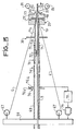
- FIG. 3 represents a sectional view of the device for manufacturing wiring elements incorporating the rotating mounted laying head according to the invention.
- a plate driven in rotation at the rate of one revolution by step of the grooves of the support 3 scrolling in translation there is shown at 66 a plate driven in rotation at the rate of one revolution by step of the grooves of the support 3 scrolling in translation.
- the optical fibers 6 are supplied by coils 67 mounted on the turntable 66, and are oriented in a beam in the direction of the laying head 10.
- On the tray 66 is mounted integrally a hollow conduit or axis 69 passing therethrough, allowing the scrolling in translation of the grooved cylindrical support 3 provided by a reserve (not shown).
- the laying head 10 is held in place by locking means, constituted for example by a bayonet system 70 mounted on one end of the tube 11.
- locking means constituted for example by a bayonet system 70 mounted on one end of the tube 11.
- the two pins 71 of the bayonet system are mounted asymmetrically on the tube part 11a, thus playing the role of a polarizer, which allows rapid and exact positioning of the laying head.
- the end face of the tube 11 compresses a spring 72 mounted in the bayonet system 70.
- the production line also includes a servo device making it possible to fix the angular position of the laying head 10 relative to the plate 66.
- This device comprises a sensor constituted for example by a potentiometer 76 in the form of a cursor 76a secured to the hollow axis 69 and moving on a conductive track 76b provided with a reference or marking intended for the subsequent restarting of the manufacturing device.
- the potentiometer 76 can be double track, or can be replaced by any type of sensor, for example optical, without departing from the scope of the invention.
- the sensor 76 delivers at its output a signal supplying a processing unit 78 which controls the angular setting of the plate 66 by means of a motor 79 coupled to the plate 66 by a gear (not shown).
- the cable element is then completed by the installation of a second protective envelope (not shown).
- a head for simultaneously laying optical fibers in a grooved cylindrical support was produced, which is particularly simple, very effective, and advantageous from the point of view of manufacturing cost.
Landscapes
- Engineering & Computer Science (AREA)
- Manufacturing & Machinery (AREA)
- Physics & Mathematics (AREA)
- General Physics & Mathematics (AREA)
- Optics & Photonics (AREA)
- Light Guides In General And Applications Therefor (AREA)
Applications Claiming Priority (2)
| Application Number | Priority Date | Filing Date | Title |
|---|---|---|---|
| FR8103062A FR2500174A1 (fr) | 1981-02-17 | 1981-02-17 | Tete de pose simultanee de fibres optiques dans un support cylindrique rainure et dispositif de fabrication d'elements de cablage comportant une telle tete |
| FR8103062 | 1981-02-17 |
Publications (2)
| Publication Number | Publication Date |
|---|---|
| EP0058594A1 EP0058594A1 (fr) | 1982-08-25 |
| EP0058594B1 true EP0058594B1 (fr) | 1985-06-19 |
Family
ID=9255285
Family Applications (1)
| Application Number | Title | Priority Date | Filing Date |
|---|---|---|---|
| EP82400175A Expired EP0058594B1 (fr) | 1981-02-17 | 1982-02-02 | Tête de pose simultanée de fibres optiques dans un support cylindrique rainuré et dispositif de fabrication d'éléments de câblage comportant une telle tête |
Country Status (6)
| Country | Link |
|---|---|
| US (1) | US4411130A (enExample) |
| EP (1) | EP0058594B1 (enExample) |
| JP (1) | JPS57151905A (enExample) |
| CA (1) | CA1197672A (enExample) |
| DE (1) | DE3264161D1 (enExample) |
| FR (1) | FR2500174A1 (enExample) |
Families Citing this family (15)
| Publication number | Priority date | Publication date | Assignee | Title |
|---|---|---|---|---|
| IT1152225B (it) * | 1982-05-31 | 1986-12-31 | Pirelli Cavi Spa | Apparecchiatura per la fabbricazione di un cavo con fibre ottiche |
| FR2549969B1 (fr) * | 1983-07-27 | 1985-09-27 | Cables De Lyon Geoffroy Delore | Procede d'injection d'un produit de remplissage visqueux dans les rainures de logement des fibres optiques d'un jonc, et dispositif de mise en oeuvre de ce procede |
| FR2565360B1 (fr) * | 1984-05-30 | 1986-09-05 | Telecommunications Sa | Systeme d'asservissement de la rotation d'un dispositif d'alimentation et de distribution de fibres optiques dans une ligne de cablage |
| IT1177431B (it) * | 1984-12-17 | 1987-08-26 | Pirelli Cavi Spa | Procedimento e linea di produzione di cavi elementari a fibre ottiche con nucleo provvisto di scanalature ad alica aperta |
| DE3503843A1 (de) * | 1985-02-05 | 1986-08-07 | Siemens AG, 1000 Berlin und 8000 München | Ablaufgestell fuer vorratsspulen |
| FR2577051B1 (fr) * | 1985-02-07 | 1989-03-31 | Lignes Telegraph Telephon | Dispositif de fabrication d'elements de cablage et tete de pose simultanee de fibres optiques dans un support cylindrique rainure pour un tel dispositif |
| FR2588095B1 (fr) * | 1985-10-01 | 1988-12-02 | Lignes Telegraph Telephon | Tete de pose de fibres optiques dans les rainures a pas alterne d'un jonc cylindrique |
| FR2611924B1 (fr) * | 1987-03-02 | 1989-06-09 | Telecommunications Sa | Dispositif d'introduction de fibres optiques dans des rainures helicoidales d'un jonc pour ligne de cablage |
| US4783954A (en) * | 1987-09-30 | 1988-11-15 | Northern Telecom Limited | Laying of elongate telecommunications transmission members onto support members |
| EP0359420A3 (en) * | 1988-09-07 | 1991-08-28 | Telephone Cables Limited | Cable core with a twisting channel, and laying optical fibre therein |
| US5644905A (en) * | 1993-10-14 | 1997-07-08 | Siemens Aktiengesellschaft | Stranding device with an exchangeable supply member and an associated method |
| WO1997006088A1 (en) * | 1995-08-04 | 1997-02-20 | Aplicator System Ab | Device for feeding a set of wires to a robot arm |
| US6419743B1 (en) | 2001-01-12 | 2002-07-16 | Fusion Uv Systems, Inc. | Apparatus and method for passing multiple fibers through a small zone of high intensity radiant energy |
| CN106194928A (zh) * | 2016-08-11 | 2016-12-07 | 宁波健信核磁技术有限公司 | 一种连接机构 |
| CN113991558B (zh) * | 2021-11-24 | 2024-02-09 | 国网山东省电力公司经济技术研究院 | 一种电线对接装置 |
Family Cites Families (13)
| Publication number | Priority date | Publication date | Assignee | Title |
|---|---|---|---|---|
| GB1544690A (en) * | 1976-08-20 | 1979-04-25 | Standard Telephones Cables Ltd | Cable making planetary strander |
| IT1065925B (it) * | 1976-09-03 | 1985-03-04 | Pirelli | Apparato per riunire tra di loro dei filamenti sottili |
| FR2418940A1 (fr) * | 1978-03-01 | 1979-09-28 | Lignes Telegraph Telephon | Perfectionnements a la fabrication d'elements de cablage comportant des fibres optiques |
| CA1093877A (en) * | 1978-06-07 | 1981-01-20 | Frederick D. King | Optical waveguide cables |
| US4195468A (en) * | 1979-01-22 | 1980-04-01 | Northern Telecom Limited | Method and apparatus for use in the assembly of optical cables |
| GB2022644B (en) * | 1978-06-07 | 1983-03-16 | Northern Telecom Ltd | Optical cable manufacute |
| US4154049A (en) * | 1978-06-08 | 1979-05-15 | Northern Telecom Limited | Method and apparatus for forming optical cables |
| US4205899A (en) * | 1978-06-08 | 1980-06-03 | Northern Telecom Limited | Optical cables |
| JPS5570807A (en) * | 1978-11-23 | 1980-05-28 | Nippon Telegr & Teleph Corp <Ntt> | Production of optical fiber cable |
| US4237687A (en) * | 1979-03-01 | 1980-12-09 | Societe Lignes Telegraphiques Et Telephoniques | Optical fibre laying head for cable production |
| FR2458086A2 (fr) * | 1979-05-30 | 1980-12-26 | Lignes Telegraph Telephon | Perfectionnements a la fabrication d'elements de cablage comportant des fibres optiques |
| US4325212A (en) * | 1980-11-20 | 1982-04-20 | Northern Telecom Limited | Laying optical waveguides and electrical conductors onto a support filament |
| US4309866A (en) * | 1980-11-20 | 1982-01-12 | Northern Telecom Limited | Laying and binding optical waveguides onto a support filament |
-
1981
- 1981-02-17 FR FR8103062A patent/FR2500174A1/fr active Granted
-
1982
- 1982-02-02 DE DE8282400175T patent/DE3264161D1/de not_active Expired
- 1982-02-02 EP EP82400175A patent/EP0058594B1/fr not_active Expired
- 1982-02-09 US US06/347,255 patent/US4411130A/en not_active Expired - Lifetime
- 1982-02-10 JP JP57019042A patent/JPS57151905A/ja active Granted
- 1982-02-15 CA CA000396290A patent/CA1197672A/en not_active Expired
Also Published As
| Publication number | Publication date |
|---|---|
| DE3264161D1 (en) | 1985-07-25 |
| JPS57151905A (en) | 1982-09-20 |
| EP0058594A1 (fr) | 1982-08-25 |
| FR2500174B1 (enExample) | 1984-08-03 |
| CA1197672A (en) | 1985-12-10 |
| JPH0534647B2 (enExample) | 1993-05-24 |
| US4411130A (en) | 1983-10-25 |
| FR2500174A1 (fr) | 1982-08-20 |
Similar Documents
| Publication | Publication Date | Title |
|---|---|---|
| EP0058594B1 (fr) | Tête de pose simultanée de fibres optiques dans un support cylindrique rainuré et dispositif de fabrication d'éléments de câblage comportant une telle tête | |
| FR2493537A1 (fr) | Dispositif de positionnement de fibres optiques dans une piece formant embout destinee au raccordement de deux cables de transmission par fibres optiques | |
| EP0020189B1 (fr) | Dispositif de fabrication d'éléments de câblage comportant des fibres optiques | |
| EP0097575A1 (fr) | Fiche pour connecteur de fibres optiques, et connecteur la comportant | |
| EP0063506A1 (fr) | Dispositif de protection de fibres optiques dégagées à l'extrémité d'un élément de câble, élément de câble muni de ce dispositif, et utilisation d'un tel élément de câble | |
| FR2485754A1 (fr) | Connecteur de fibres optiques | |
| FR2591466A1 (fr) | Table d'examen a deplacement longitudinal d'un panneau | |
| EP0078196B1 (fr) | Dispositif de préparation en nappe des extrémités de fibres optiques reparties autour d'une structure à symétrie axiale | |
| CA1103908A (fr) | Fabrication d'elements de cablage comportant des fibres optiques | |
| EP0029383A1 (fr) | Dispositif d'aboutement de deux fibres optiques | |
| EP0520946A1 (fr) | Dispositif d'extrémité pour câble optique | |
| EP0036369A1 (fr) | Procédé et dispositif de raccordement sur chantier de câbles à fibres optiques | |
| EP0096608B1 (fr) | Collimateur pour fibre optique, application à la réalisation de dispositifs de commutation optique | |
| EP0098190B1 (fr) | Dispositif de connexion et d'alignement de deux embouts de raccordement de fibres optiques en forme de V | |
| EP0282383A1 (fr) | Dispositif d'introduction de fibres optiques dans des rainures hélicoidales d'un jonc pour ligne de câblage | |
| FR2631405A1 (fr) | Frein a disque et systeme de support pour un tel frein | |
| EP0056541B1 (fr) | Dispositif de support d'un outil d'usinage d'une tige cylindrique et tête d'usinage comportant un tel dispositif | |
| FR2807513A1 (fr) | Dispositif de positionnement de pieces de machine deplacees en ligne droite ou en rotation | |
| EP0480852A1 (fr) | Machine de câblage de fils comportant un dispositif régulateur perfectionné | |
| EP3553576B1 (fr) | Faisceau de fibres optiques liées entre elles avec de l'adhésif, procédé et dispositif d'obtention d'un tel faisceau | |
| FR2564987A1 (fr) | Ligne de fabrication d'un element de cable a fibres optiques | |
| FR2497965A1 (fr) | Dispositif d'insertion notamment de fibres optiques dans des rainures helicoidales | |
| EP0316684A2 (fr) | Support pour élément optique | |
| FR2622366A1 (fr) | Dispositif permettant de denuder l'extremite d'un cable | |
| WO2020011859A1 (fr) | Dispositif d'acheminement de fibres pour une machine d'application de fibres |
Legal Events
| Date | Code | Title | Description |
|---|---|---|---|
| PUAI | Public reference made under article 153(3) epc to a published international application that has entered the european phase |
Free format text: ORIGINAL CODE: 0009012 |
|
| AK | Designated contracting states |
Designated state(s): BE CH DE GB IT |
|
| 17P | Request for examination filed |
Effective date: 19821004 |
|
| ITF | It: translation for a ep patent filed | ||
| GRAA | (expected) grant |
Free format text: ORIGINAL CODE: 0009210 |
|
| AK | Designated contracting states |
Designated state(s): BE CH DE GB IT LI |
|
| REF | Corresponds to: |
Ref document number: 3264161 Country of ref document: DE Date of ref document: 19850725 |
|
| PLBE | No opposition filed within time limit |
Free format text: ORIGINAL CODE: 0009261 |
|
| STAA | Information on the status of an ep patent application or granted ep patent |
Free format text: STATUS: NO OPPOSITION FILED WITHIN TIME LIMIT |
|
| 26N | No opposition filed | ||
| ITTA | It: last paid annual fee | ||
| PGFP | Annual fee paid to national office [announced via postgrant information from national office to epo] |
Ref country code: GB Payment date: 19970113 Year of fee payment: 16 |
|
| PGFP | Annual fee paid to national office [announced via postgrant information from national office to epo] |
Ref country code: BE Payment date: 19970116 Year of fee payment: 16 |
|
| PGFP | Annual fee paid to national office [announced via postgrant information from national office to epo] |
Ref country code: DE Payment date: 19970124 Year of fee payment: 16 |
|
| PGFP | Annual fee paid to national office [announced via postgrant information from national office to epo] |
Ref country code: CH Payment date: 19970130 Year of fee payment: 16 |
|
| PG25 | Lapsed in a contracting state [announced via postgrant information from national office to epo] |
Ref country code: GB Free format text: LAPSE BECAUSE OF NON-PAYMENT OF DUE FEES Effective date: 19980202 |
|
| PG25 | Lapsed in a contracting state [announced via postgrant information from national office to epo] |
Ref country code: LI Free format text: LAPSE BECAUSE OF NON-PAYMENT OF DUE FEES Effective date: 19980228 Ref country code: CH Free format text: LAPSE BECAUSE OF NON-PAYMENT OF DUE FEES Effective date: 19980228 Ref country code: BE Free format text: LAPSE BECAUSE OF NON-PAYMENT OF DUE FEES Effective date: 19980228 |
|
| BERE | Be: lapsed |
Owner name: LIGNES TELEGRAPHIQUES ET TELEPHONIQUES LTT Effective date: 19980228 |
|
| GBPC | Gb: european patent ceased through non-payment of renewal fee |
Effective date: 19980202 |
|
| REG | Reference to a national code |
Ref country code: CH Ref legal event code: PL |
|
| PG25 | Lapsed in a contracting state [announced via postgrant information from national office to epo] |
Ref country code: DE Free format text: LAPSE BECAUSE OF NON-PAYMENT OF DUE FEES Effective date: 19981103 |