EP0058461B1 - End capping an optical fiber - Google Patents
End capping an optical fiber Download PDFInfo
- Publication number
- EP0058461B1 EP0058461B1 EP82200185A EP82200185A EP0058461B1 EP 0058461 B1 EP0058461 B1 EP 0058461B1 EP 82200185 A EP82200185 A EP 82200185A EP 82200185 A EP82200185 A EP 82200185A EP 0058461 B1 EP0058461 B1 EP 0058461B1
- Authority
- EP
- European Patent Office
- Prior art keywords
- layer
- fiber
- hardenable
- optical fiber
- film
- Prior art date
- Legal status (The legal status is an assumption and is not a legal conclusion. Google has not performed a legal analysis and makes no representation as to the accuracy of the status listed.)
- Expired
Links
- 239000013307 optical fiber Substances 0.000 title claims abstract description 34
- 239000000835 fiber Substances 0.000 claims abstract description 57
- 239000000758 substrate Substances 0.000 claims abstract description 4
- 238000000034 method Methods 0.000 claims description 32
- -1 polyethylene terephthalate Polymers 0.000 claims description 20
- 239000000203 mixture Substances 0.000 claims description 14
- 229920000139 polyethylene terephthalate Polymers 0.000 claims description 10
- 239000005020 polyethylene terephthalate Substances 0.000 claims description 10
- 229920000642 polymer Polymers 0.000 claims description 10
- 239000004698 Polyethylene Substances 0.000 claims description 8
- 229920000573 polyethylene Polymers 0.000 claims description 8
- 230000003287 optical effect Effects 0.000 claims description 6
- 229920001169 thermoplastic Polymers 0.000 claims description 5
- 239000004416 thermosoftening plastic Substances 0.000 claims description 5
- VVBLNCFGVYUYGU-UHFFFAOYSA-N 4,4'-Bis(dimethylamino)benzophenone Chemical compound C1=CC(N(C)C)=CC=C1C(=O)C1=CC=C(N(C)C)C=C1 VVBLNCFGVYUYGU-UHFFFAOYSA-N 0.000 claims description 4
- QVGXLLKOCUKJST-UHFFFAOYSA-N atomic oxygen Chemical compound [O] QVGXLLKOCUKJST-UHFFFAOYSA-N 0.000 claims description 4
- 229920001577 copolymer Polymers 0.000 claims description 4
- 239000001301 oxygen Substances 0.000 claims description 4
- 229910052760 oxygen Inorganic materials 0.000 claims description 4
- 239000004342 Benzoyl peroxide Substances 0.000 claims description 3
- OMPJBNCRMGITSC-UHFFFAOYSA-N Benzoylperoxide Chemical compound C=1C=CC=CC=1C(=O)OOC(=O)C1=CC=CC=C1 OMPJBNCRMGITSC-UHFFFAOYSA-N 0.000 claims description 3
- 229920003171 Poly (ethylene oxide) Polymers 0.000 claims description 3
- 235000019400 benzoyl peroxide Nutrition 0.000 claims description 3
- CMCBDXRRFKYBDG-UHFFFAOYSA-N 1-dodecoxydodecane Chemical compound CCCCCCCCCCCCOCCCCCCCCCCCC CMCBDXRRFKYBDG-UHFFFAOYSA-N 0.000 claims 2
- FLFWJIBUZQARMD-UHFFFAOYSA-N 2-mercapto-1,3-benzoxazole Chemical compound C1=CC=C2OC(S)=NC2=C1 FLFWJIBUZQARMD-UHFFFAOYSA-N 0.000 claims 2
- ZJCCRDAZUWHFQH-UHFFFAOYSA-N Trimethylolpropane Chemical compound CCC(CO)(CO)CO ZJCCRDAZUWHFQH-UHFFFAOYSA-N 0.000 claims 2
- DAKWPKUUDNSNPN-UHFFFAOYSA-N Trimethylolpropane triacrylate Chemical compound C=CC(=O)OCC(CC)(COC(=O)C=C)COC(=O)C=C DAKWPKUUDNSNPN-UHFFFAOYSA-N 0.000 claims 2
- 229940096522 trimethylolpropane triacrylate Drugs 0.000 claims 2
- 230000000379 polymerizing effect Effects 0.000 claims 1
- 239000000463 material Substances 0.000 abstract description 23
- 239000010410 layer Substances 0.000 description 50
- 239000010408 film Substances 0.000 description 37
- 238000010438 heat treatment Methods 0.000 description 7
- 230000005855 radiation Effects 0.000 description 7
- 239000000178 monomer Substances 0.000 description 6
- 238000012644 addition polymerization Methods 0.000 description 5
- 230000005540 biological transmission Effects 0.000 description 5
- 239000011248 coating agent Substances 0.000 description 5
- 238000000576 coating method Methods 0.000 description 5
- 230000004907 flux Effects 0.000 description 5
- 150000003254 radicals Chemical class 0.000 description 5
- 238000005259 measurement Methods 0.000 description 4
- 239000010409 thin film Substances 0.000 description 4
- YMWUJEATGCHHMB-UHFFFAOYSA-N Dichloromethane Chemical compound ClCCl YMWUJEATGCHHMB-UHFFFAOYSA-N 0.000 description 3
- VYPSYNLAJGMNEJ-UHFFFAOYSA-N Silicium dioxide Chemical compound O=[Si]=O VYPSYNLAJGMNEJ-UHFFFAOYSA-N 0.000 description 3
- 238000005253 cladding Methods 0.000 description 3
- 230000006835 compression Effects 0.000 description 3
- 238000007906 compression Methods 0.000 description 3
- 239000003822 epoxy resin Substances 0.000 description 3
- 239000003999 initiator Substances 0.000 description 3
- 229920003023 plastic Polymers 0.000 description 3
- 239000004033 plastic Substances 0.000 description 3
- 229920000647 polyepoxide Polymers 0.000 description 3
- 239000003505 polymerization initiator Substances 0.000 description 3
- 230000001681 protective effect Effects 0.000 description 3
- 229920005989 resin Polymers 0.000 description 3
- 239000011347 resin Substances 0.000 description 3
- 229920001187 thermosetting polymer Polymers 0.000 description 3
- XUIMIQQOPSSXEZ-UHFFFAOYSA-N Silicon Chemical compound [Si] XUIMIQQOPSSXEZ-UHFFFAOYSA-N 0.000 description 2
- RWCCWEUUXYIKHB-UHFFFAOYSA-N benzophenone Chemical compound C=1C=CC=CC=1C(=O)C1=CC=CC=C1 RWCCWEUUXYIKHB-UHFFFAOYSA-N 0.000 description 2
- 239000012965 benzophenone Substances 0.000 description 2
- 239000000470 constituent Substances 0.000 description 2
- 238000004132 cross linking Methods 0.000 description 2
- 238000001035 drying Methods 0.000 description 2
- 239000003365 glass fiber Substances 0.000 description 2
- 239000012188 paraffin wax Substances 0.000 description 2
- 239000002245 particle Substances 0.000 description 2
- 238000005498 polishing Methods 0.000 description 2
- 239000004848 polyfunctional curative Substances 0.000 description 2
- 238000006116 polymerization reaction Methods 0.000 description 2
- 239000011241 protective layer Substances 0.000 description 2
- 229910052710 silicon Inorganic materials 0.000 description 2
- 239000010703 silicon Substances 0.000 description 2
- 238000003860 storage Methods 0.000 description 2
- 229920002554 vinyl polymer Polymers 0.000 description 2
- OVOUKWFJRHALDD-UHFFFAOYSA-N 2-[2-(2-acetyloxyethoxy)ethoxy]ethyl acetate Chemical compound CC(=O)OCCOCCOCCOC(C)=O OVOUKWFJRHALDD-UHFFFAOYSA-N 0.000 description 1
- DQFBYFPFKXHELB-UHFFFAOYSA-N Chalcone Natural products C=1C=CC=CC=1C(=O)C=CC1=CC=CC=C1 DQFBYFPFKXHELB-UHFFFAOYSA-N 0.000 description 1
- 229920003345 Elvax® Polymers 0.000 description 1
- VGGSQFUCUMXWEO-UHFFFAOYSA-N Ethene Chemical compound C=C VGGSQFUCUMXWEO-UHFFFAOYSA-N 0.000 description 1
- 239000005977 Ethylene Substances 0.000 description 1
- 229910019142 PO4 Inorganic materials 0.000 description 1
- 239000002202 Polyethylene glycol Substances 0.000 description 1
- 239000004372 Polyvinyl alcohol Substances 0.000 description 1
- 230000004913 activation Effects 0.000 description 1
- 239000000654 additive Substances 0.000 description 1
- 239000000853 adhesive Substances 0.000 description 1
- 230000001070 adhesive effect Effects 0.000 description 1
- 239000012790 adhesive layer Substances 0.000 description 1
- 150000001338 aliphatic hydrocarbons Chemical class 0.000 description 1
- 239000011230 binding agent Substances 0.000 description 1
- 235000005513 chalcones Nutrition 0.000 description 1
- 239000003795 chemical substances by application Substances 0.000 description 1
- 229940114081 cinnamate Drugs 0.000 description 1
- 150000001851 cinnamic acid derivatives Chemical class 0.000 description 1
- 239000008199 coating composition Substances 0.000 description 1
- 239000002131 composite material Substances 0.000 description 1
- 150000001875 compounds Chemical class 0.000 description 1
- 238000006471 dimerization reaction Methods 0.000 description 1
- 238000009826 distribution Methods 0.000 description 1
- 239000000428 dust Substances 0.000 description 1
- 238000001704 evaporation Methods 0.000 description 1
- 230000008020 evaporation Effects 0.000 description 1
- 239000011521 glass Substances 0.000 description 1
- 230000005484 gravity Effects 0.000 description 1
- 238000000227 grinding Methods 0.000 description 1
- LNEPOXFFQSENCJ-UHFFFAOYSA-N haloperidol Chemical compound C1CC(O)(C=2C=CC(Cl)=CC=2)CCN1CCCC(=O)C1=CC=C(F)C=C1 LNEPOXFFQSENCJ-UHFFFAOYSA-N 0.000 description 1
- 238000007689 inspection Methods 0.000 description 1
- 230000002427 irreversible effect Effects 0.000 description 1
- 239000007788 liquid Substances 0.000 description 1
- 230000007774 longterm Effects 0.000 description 1
- QSHDDOUJBYECFT-UHFFFAOYSA-N mercury Chemical compound [Hg] QSHDDOUJBYECFT-UHFFFAOYSA-N 0.000 description 1
- 229910052753 mercury Inorganic materials 0.000 description 1
- 238000002156 mixing Methods 0.000 description 1
- 235000021317 phosphate Nutrition 0.000 description 1
- 229920002120 photoresistant polymer Polymers 0.000 description 1
- 125000005498 phthalate group Chemical class 0.000 description 1
- 239000004014 plasticizer Substances 0.000 description 1
- 238000007517 polishing process Methods 0.000 description 1
- 229920001223 polyethylene glycol Polymers 0.000 description 1
- 229920005596 polymer binder Polymers 0.000 description 1
- 239000002491 polymer binding agent Substances 0.000 description 1
- 229920005862 polyol Polymers 0.000 description 1
- 150000003077 polyols Chemical class 0.000 description 1
- 229920002451 polyvinyl alcohol Polymers 0.000 description 1
- 230000001902 propagating effect Effects 0.000 description 1
- 238000000926 separation method Methods 0.000 description 1
- 239000000377 silicon dioxide Substances 0.000 description 1
- 239000002904 solvent Substances 0.000 description 1
- 239000000126 substance Substances 0.000 description 1
- 229920002803 thermoplastic polyurethane Polymers 0.000 description 1
- DQFBYFPFKXHELB-VAWYXSNFSA-N trans-chalcone Chemical compound C=1C=CC=CC=1C(=O)\C=C\C1=CC=CC=C1 DQFBYFPFKXHELB-VAWYXSNFSA-N 0.000 description 1
- 125000000391 vinyl group Chemical group [H]C([*])=C([H])[H] 0.000 description 1
- 229910052724 xenon Inorganic materials 0.000 description 1
- FHNFHKCVQCLJFQ-UHFFFAOYSA-N xenon atom Chemical compound [Xe] FHNFHKCVQCLJFQ-UHFFFAOYSA-N 0.000 description 1
Images


Classifications
-
- G—PHYSICS
- G02—OPTICS
- G02B—OPTICAL ELEMENTS, SYSTEMS OR APPARATUS
- G02B6/00—Light guides; Structural details of arrangements comprising light guides and other optical elements, e.g. couplings
- G02B6/24—Coupling light guides
-
- G—PHYSICS
- G02—OPTICS
- G02B—OPTICAL ELEMENTS, SYSTEMS OR APPARATUS
- G02B6/00—Light guides; Structural details of arrangements comprising light guides and other optical elements, e.g. couplings
- G02B6/24—Coupling light guides
- G02B6/36—Mechanical coupling means
- G02B6/38—Mechanical coupling means having fibre to fibre mating means
- G02B6/3807—Dismountable connectors, i.e. comprising plugs
- G02B6/3833—Details of mounting fibres in ferrules; Assembly methods; Manufacture
- G02B6/3855—Details of mounting fibres in ferrules; Assembly methods; Manufacture characterised by the method of anchoring or fixing the fibre within the ferrule
- G02B6/3861—Adhesive bonding
-
- G—PHYSICS
- G02—OPTICS
- G02B—OPTICAL ELEMENTS, SYSTEMS OR APPARATUS
- G02B6/00—Light guides; Structural details of arrangements comprising light guides and other optical elements, e.g. couplings
- G02B6/10—Light guides; Structural details of arrangements comprising light guides and other optical elements, e.g. couplings of the optical waveguide type
- G02B6/14—Mode converters
-
- G—PHYSICS
- G02—OPTICS
- G02B—OPTICAL ELEMENTS, SYSTEMS OR APPARATUS
- G02B6/00—Light guides; Structural details of arrangements comprising light guides and other optical elements, e.g. couplings
- G02B6/24—Coupling light guides
- G02B6/241—Light guide terminations
-
- G—PHYSICS
- G02—OPTICS
- G02B—OPTICAL ELEMENTS, SYSTEMS OR APPARATUS
- G02B6/00—Light guides; Structural details of arrangements comprising light guides and other optical elements, e.g. couplings
- G02B6/24—Coupling light guides
- G02B6/36—Mechanical coupling means
- G02B6/38—Mechanical coupling means having fibre to fibre mating means
- G02B6/3807—Dismountable connectors, i.e. comprising plugs
-
- G—PHYSICS
- G02—OPTICS
- G02B—OPTICAL ELEMENTS, SYSTEMS OR APPARATUS
- G02B6/00—Light guides; Structural details of arrangements comprising light guides and other optical elements, e.g. couplings
- G02B6/24—Coupling light guides
- G02B6/42—Coupling light guides with opto-electronic elements
- G02B6/4201—Packages, e.g. shape, construction, internal or external details
- G02B6/4202—Packages, e.g. shape, construction, internal or external details for coupling an active element with fibres without intermediate optical elements, e.g. fibres with plane ends, fibres with shaped ends, bundles
- G02B6/4203—Optical features
-
- G—PHYSICS
- G02—OPTICS
- G02B—OPTICAL ELEMENTS, SYSTEMS OR APPARATUS
- G02B6/00—Light guides; Structural details of arrangements comprising light guides and other optical elements, e.g. couplings
- G02B6/24—Coupling light guides
- G02B6/36—Mechanical coupling means
- G02B6/38—Mechanical coupling means having fibre to fibre mating means
- G02B6/3807—Dismountable connectors, i.e. comprising plugs
- G02B6/3833—Details of mounting fibres in ferrules; Assembly methods; Manufacture
- G02B6/3847—Details of mounting fibres in ferrules; Assembly methods; Manufacture with means preventing fibre end damage, e.g. recessed fibre surfaces
-
- G—PHYSICS
- G02—OPTICS
- G02B—OPTICAL ELEMENTS, SYSTEMS OR APPARATUS
- G02B6/00—Light guides; Structural details of arrangements comprising light guides and other optical elements, e.g. couplings
- G02B6/24—Coupling light guides
- G02B6/36—Mechanical coupling means
- G02B6/38—Mechanical coupling means having fibre to fibre mating means
- G02B6/3807—Dismountable connectors, i.e. comprising plugs
- G02B6/3833—Details of mounting fibres in ferrules; Assembly methods; Manufacture
- G02B6/3863—Details of mounting fibres in ferrules; Assembly methods; Manufacture fabricated by using polishing techniques
Definitions
- This invention relates to a process for capping the end of an optical fiber with a hardenable material. More particularly, it refers to a process for immersing a rough cut end of an optical fiber in a thin, light-transmissible, hardenable material supported on a smooth film or other smooth substrate to form a smooth light transmissible flat surface at the end of the fiber.
- Optical fiber lengths of sufficiently good quality to produce low light loss in connectors can be made by abrasive polishing of the cut fiber end with successive finer grits.
- the abrasive medium is kept wet to provide lubricity and to assist the floating away of loose material. Successive polishing and inspection steps are employed until observation, usually with a microscope, shows that all scratches have disappeared. This method is time consuming and requires considerable operator skill. In addition, such a method is not easily adaptable to automatic machines. There is need, therefore, for a rapid method to generate an optically smooth end surface on an optical fiber which will minimize light losses when two such ends are brought into contact or preferably near-contact as in the case of a light conducting fiber optic connector.
- the present invention solves the above problems by providing the steps specified in claim 1.
- a flat, optically clear, terminal surface or cap at the end of an optical fiber is provided.
- the cap permits maximum light transmission without need for compression beyond that necessary to insure contact between the optical fiber end and a hardenable material.
- Such a cap providing low optical scattering loss, may be readily produced at the end of a cut optical fiber through a process comprising contacting a cut fiber end to a thin, light-transmissible, hardenable layer supported on a smooth film so as to embed said fiber in said hardenable layer, and then hardening the layer while the fiber remains embedded to form a smooth, flat surface at the end of the fiber.
- the desirable end capped optical fiber is attained by first coating a thin polyethylene terephthalate or similar transparent film 46 approximately 0.0234 mm thick with a hardenable material 44 as in Fig. 6, drying this coating, and covering it with a protective film layer 48 which allows the composite film 20 to be stored and transported in contact with itself.
- Film 20 containing the hardenable material 44 is pulled from a storage reel 24 through an energy transmissible hardening zone 32 on a film-support base 30.
- a roller 26 strips the protective film 48 before the film 20 reaches the hardening zone 32.
- An optical fiber 10 from a fiber optical cable is fed through an optical fiber connector 14 and gripped by the connector end 12.
- the optical fiber 10 with its cladding 11 surrounding its core is allowed to protrude approximately 1 mm from the end 12 of the connector 14.
- the optical fiber end 16 has been previously cut or equivalently fractured substantially perpendicular to its axis.
- the connector 14 is mounted within a housing 19 having a movable part 17 and a fixed part 18. It is guided by mechanical or electrical means toward the energy source 22 on the opposite side from the film support base 30. See Fig. 1.
- the end 16 of the optical fiber contacts the film strip 20 containing a thin coating of a hardenable material 44.
- the rough cut end 16 of the optical fiber 10 is embedded within the hardenable layer on the surface of the film.
- the energy source such as light source 22 is caused to impinge upon the rough cut fiber end 16 now containing the hardenable material 44, either by controlled electrical activation or by action of shutter 34.
- the hardenable material thereafter hardens by virtue of exposure to the energy source.
- the hardenable layer 44 should be sufficiently thick to fill the surface depressions on the rough cut end 16 of the optical fiber, which depressions typically range in maximum depth from 2 ⁇ m to 20 ⁇ m.
- the hardenable layer should not be so thick that the axial separation it introduces between two juxtaposed fiber ends increases the optical flux loss at this juncture by more than approximately 2 db.
- This maximum thickness of the hardenable layer depends on several parameters of the optical fiber to be end-capped, but most strongly on its core diameter and its numerical aperture (NA), which latter is defined as the sine of the angle at which the far-field angular distribution of light intensity exiting the fiber fails to 10% of its axial value. It has been found experimentally that a useful approximation for this maximum thickness is provided by the relationship
- the remaining film strip after removal of the hardenable layer, continues onto reel 28.
- Another connector containing a rough cut optical fiber end can be inserted into the housing 19 and the process continued as the film strip 20 moves across the support 30.
- the film strip 20 is punched out at the point of impact with the optical fiber end 16 so that the capped optical fiber end 40 has a coat of hardenable material 44 and the thin film 46. See Figs. 7 and 9.
- the thin film 46 can be left on the fiber end or can be subsequentlv removed.
- the film 46 supporting the hardenable layer 44 is removed while the hardenable layer remains on said capped fiber end 40 as shown in Fig. 3.
- optical fiber employed in this invention can be any of the glass or plastic, fibers employed in fiber optic communications, provided that the constituents of the hardenable layer do not dissolve or otherwise- physically or chemically attack the elements of the fiber.
- the thin film base can be any tight transmissible film capable of supporting a hardenable material.
- the preferred films are polyethylene terephthalate and polyethylene.
- the hardenable layer must be light transmissible in the same wavelength band used to transmit information through the optical fiber and preferably is a photohardenable composition.
- suitable photohardenable compositions are: (1) those in which a photopolymerizable monomer is present, preferably in combination with a compatible binder or (2) those in which a photopolymerizable group attached to a polymer backbone becomes activated through light source 22 and may then crosslink by acting with a similar group or other reactive sites on adjacent polymer chains.
- the photopolymerized chain length may involve addition of many similar units initiated by a single photochemical event.
- dimerization e.g., with benzophenone or cinnamoyl compounds
- the average molecular weight of the photosensitive constituent can be, at best, only doubled by a single photochemical act.
- a photopolymerizable molecule has more than one reactive site, a crosslinked network can be produced.
- the photosensitive layer preferably contains a free radical generating, addition polymerization initiator. Plasticizing agents as well as other known additives can be present in the photosensitive layer.
- Suitable free radical initiated, chain propagating, addition polymerizable, ethylenically unsaturated compounds for use in the monomer or monomer-polymer binder photopolymerizable layers are described in U.S. Patents 3,060,023, 3,261,686, 3,380,831 and 3,649,268.
- Polymers for use in the monomer-polymer system and preferred free radical generating addition polymerization in initiators are described in U.S. Patent 3,060,023. These patents are herein incorporated by reference.
- Photodimerizable materials useful in the invention are cinnamic acid esters of high molecular weight polyols, polymers having chalcone and benzophenone type groups, and others disclosed in Chapter 4 of "Light Sensitive Systems” by Jaromir Kosar, published by John Wiley and Sons, Inc., N.Y., -165. Photopolymerizable materials capable of crosslinking with more than one adjacent polymeric chain to form a network are described in U.S. Patents 3,418,295 and 3,469,982. These patents are also herein incorporated by reference.
- Preferred free radical generating addition polymerization initiators activatable by actinic radiation, e.g., ultraviolet invisible radiation are listed in U.S. Patent 3,060,023 and the other patents referred to above.
- Suitable plasticizers include: dialkyl phthalates, polyoxyethylene(4)monolaurylether, polyethylene glycol, triethylene glycol diacetate, alkyl phosphates, etc.
- the hardenable layer may be one which is thermally curable as shown in Fig. 4.
- thermally curable layers may include thermosetting layers such as clear epoxy resins which harden either at room temperature or upon exposure to elevated temperatures and in which such hardening is an irreversible setting process.
- thermosetting layers such as clear epoxy resins which harden either at room temperature or upon exposure to elevated temperatures and in which such hardening is an irreversible setting process.
- Either one- or two-part epoxy resin systems may be employed, and when a two-part system is used, the components may be premixed and then applied as a layer, or two separate layers may be applied in a sequential application.
- Thermally polymerizable layers may be used in which, rather than the free radical generating addition polymerization initiators activatable by actinic radiation referred to above, a thermally activatable initiator such as benzoyl peroxide may be used in which case hardening proceeds via polymerization of the monomers initiated by heating.
- a thermally activatable initiator such as benzoyl peroxide may be used in which case hardening proceeds via polymerization of the monomers initiated by heating.
- the end caps may also be produced using hardenable layers which exhibit thermoplastic properties.
- thermoplastic properties mean a layer which can be softened by heating to a temperature above room temperature and then hardened by recooling to room temperature.
- Such layers may be polymeric or nonpolymeric, such as paraffin, which can be softened by heating to 50 to 60°C and hardened by recooling to room temperature.
- the preferred hardenable materials are photopolymers described in U.S. Patent 3,649,268 and in Example II below.
- a thin layer of a hardenable composition is coated on a transparent supporting base such as a thin sheet of polyethylene terephthalate film base. After drying, the coating is optionally covered with a protective layer, such as a thin sheet of polyethylene, to facilitate temporary storage.
- LED light-emitting diode
- the fiber is then cut approximately two meters from the detecting PIN diode end.
- the cut ends are rough-ground perpendicular to the fiber axis using 40/,um abrasive particles.
- the ends are cleaned with an air blast to remove lingering ground particles or dust.
- the protective layer if employed, is removed from the coated hardenable layer and the fiber end is brought into contact with the coated hardenable layer and pressed therein. While the fiber end is thus embedded, the layer is hardened, as described in the specific examples below.
- the now capped ends are abutted in perfect alignment.
- the reconnected 50 meters of optical fiber again transmit flux between the LED and silicon PIN detector diode. This transmitted flux is measured and the ratio of flux transmitted through the two connected fiber sections to that transmitted through the unbroken fiber is determined. This ratio is then converted to decibels (db) by taking the negative of 10 times its logarithm and the resulting number used to indicate the power loss in the various end-capping methods.
- db decibels
- the final values have been corrected for long term drift of the testing apparatus.
- the accuracy of the reported results is estimated to be within ⁇ 0.4 of the reported db value.
- a 0.0008 inch (0.020 mm) thick strip of positive working Cromalin@ 4/C proofing film commercially available from E. I. du Pont de Nemours and Company and which comprises a polyethylene terephthalate film base coated with a photohardenable, photopolymerizable layer.
- a fiber, its end cut and prepared as disclosed above, is then embedded into the photohardenable layer and exposed to UV radiation through the film base using a mercury short-arc lamp as source.
- the hardenable composition hardens in the area exposed to the UV radiation in the absence of a continuing supply of oxygen. The only such area is the area in contact with the fiber end.
- the fiber end serves as a seal preventing atmospheric oxygen from reaching the photohardenable layer from one side, and the supporting base prevents oxygen from reaching the photohardenable layer from the other side.
- the transmission loss with the film base still attached to the end of the fiber is measured as disclosed above and is found to be 0.9 db.
- a photopolymerizable composition comprising: dissolved in 720 ml of methylene chloride, is coated on a polyethylene terephthalate transparent film base 0.00092 inches (0.0234 mm) thick.
- Example 2 Using the same procedure as for Example 1 except that the UV radiation is obtained from a xenon flash tube, a loss of 2.4 db is measured. Following this measurement, the polyethylene terephthalate film is removed from the fiber end leaving adhered onto the fiber end the photopolymerized, hardened layer. Loss measurements are repeated and the loss is found to be 1.6 db.
- a photocrosslinkable hardenable layer is. used such as KPR photoresist available commercially from the Eastman Kodak Company, in which hardening proceeds through the exposure to UV radiation and the subsequent crosslinking of polyvinyl alcohol/polyvinyl cinnamate copolymer chains.
- This layer supported on a polyethylene base 0.001 inch (0.025 mm) thick, is used as in Example 1 above to provide a cap at the end of a fiber optic cable. Measurements indicate a 1.8 db loss with the film base attached to the end of the fiber and 1.3 db loss with the film base removed.
- thermosetting layer is coated on a thin film sheet of polyethylene 0.0254 mm thick.
- the thermosetting layer comprises a commercially available two-part epoxy resin and hardener adhesive available through Tra-Con, Inc. of Medford, Mass. under the trade name Tra-Bond 2101, having a specific gravity of 1.20 and a viscosity after mixing of 190 poise at 25°C. It is mixed in proportions by weight of 25 parts of hardener to 100 parts of resin.
- the fiber optic end is embedded in the hardenable layer and the layer allowed to set for a period of 18 hours at 20 ⁇ 25°C. Transmission loss is again measured as described above in Example 2, first with the polyethylene base left on the fiber, and then with the base removed and the set adhesive layer alone forming a cap to the fiber. In both instances, loss is measured as 1.0 db.
- a thermally polymerizable layer is used. as a hardenable layer which comprises the composition shown in Example 2 above, but in which the 2,2'-(o-chforophenyl)-4,4',5,5'-tetraphenylbimidazole and Michler's ketone are replaced by 6.5 g of a thermally sensitive initiator, benzoyl peroxide.
- the resulting composition is coated on polyethylene terephthalate base 0.00092 inch (.0234 mm) thick, and the fiber end is embedded therein. Following exposure to heat at 70° C for 60 min., whereby polymerization hardens the layer, transmission loss is measured as 1.7 db both with and without the film base present.
- thermoplastic layer comprising a mixture of an ethylene/vinyl acetate copolymer, ElvaX@ 210, available commercially through E. I. du Pont de Nemours and Company and a tackifying resin, Escorez® 5280, an aliphatic hydrocarbon tackifying resin made by Exxon Corp., in a 35/65 ratio by weight is coated on a 0.001 inch (0.00254 mm) polyethylene base.
- This composition is hard at normal room temperatures but may be softened by heating to 80-120 0 C. The layer is softened by heating to 80°C, a temperature low enough to not affect either glass fiber or the protective cladding, and while soft, the glass fiber end is embedded therein. It is then cooled to room temperature (20°C), whereupon the thermoplastic layer becomes hard.
- transmission loss is measured with the polyethylene film present as part of the end cap and recorded as 1.8 db.
- the same composition is then coated onto a sheet of polyethylene terephthalate base, 0.00092 inches (0.0234 mm) and the procedure is repeated. Loss is measured as 1.6 db.
- the film base is removed by peeling it off from the fiber end, leaving behind the hardened layer. The light loss is measured as 1.1 db.
- a nonpolymeric hardenable layer, paraffin, which can be softened by heating to a temperature of about 50° to 60°C and which is hard at room temperature is coated on a polyethylene terephthalate base as in Example 6. Following the same procedure as in Example 6, but heating it only to about 60°C, loss measurements are recorded. as 0.8 db with the film base as part of the end cap and 0.6 db with the film base removed.
Landscapes
- Physics & Mathematics (AREA)
- General Physics & Mathematics (AREA)
- Optics & Photonics (AREA)
- Optical Fibers, Optical Fiber Cores, And Optical Fiber Bundles (AREA)
- Surface Treatment Of Glass Fibres Or Filaments (AREA)
- Optical Couplings Of Light Guides (AREA)
- Light Guides In General And Applications Therefor (AREA)
- Removal Of Insulation Or Armoring From Wires Or Cables (AREA)
- Mechanical Coupling Of Light Guides (AREA)
- Optical Integrated Circuits (AREA)
Abstract
Description
- This invention relates to a process for capping the end of an optical fiber with a hardenable material. More particularly, it refers to a process for immersing a rough cut end of an optical fiber in a thin, light-transmissible, hardenable material supported on a smooth film or other smooth substrate to form a smooth light transmissible flat surface at the end of the fiber.
- Optical fiber lengths of sufficiently good quality to produce low light loss in connectors can be made by abrasive polishing of the cut fiber end with successive finer grits. In practice, the abrasive medium is kept wet to provide lubricity and to assist the floating away of loose material. Successive polishing and inspection steps are employed until observation, usually with a microscope, shows that all scratches have disappeared. This method is time consuming and requires considerable operator skill. In addition, such a method is not easily adaptable to automatic machines. There is need, therefore, for a rapid method to generate an optically smooth end surface on an optical fiber which will minimize light losses when two such ends are brought into contact or preferably near-contact as in the case of a light conducting fiber optic connector.
- It is desirable to have a procedure producing an end surface on a cut fiber which will contribute less than 1.0 db loss in the light transmitted through a connection between two similarly treated and accurately juxtaposed fibers. It is also highly desirable that such ends be produced either by unskilled labor or in automated equipment.
- In an effort to resolve the problems presented by the grinding and polishing process, it has been proposed to utilize a fiber end coating material such as thermoplastic urethane which is cast onto the end of a fiber to produce a button-like cap. This button elastically deforms under pressure to provide good optical contact when used with a compression type connector. This method is described in U.S. Patent No. 4,221,461. Unfortunately this procedure still does not solve all the problems since it involves on-the-spot application of a liquid substance to the fiber end and subsequent evaporation of a solvent before a cap is developed. In addition, since the final shape of the cap is not flat, compression is needed to maintain good optical qualities, necessitating a more complicated connector.
- The present invention solves the above problems by providing the steps specified in claim 1. Thus, a flat, optically clear, terminal surface or cap at the end of an optical fiber is provided. The cap permits maximum light transmission without need for compression beyond that necessary to insure contact between the optical fiber end and a hardenable material.
- Such a cap, providing low optical scattering loss, may be readily produced at the end of a cut optical fiber through a process comprising contacting a cut fiber end to a thin, light-transmissible, hardenable layer supported on a smooth film so as to embed said fiber in said hardenable layer, and then hardening the layer while the fiber remains embedded to form a smooth, flat surface at the end of the fiber.
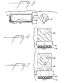
- Fig. 1 is a section through an apparatus holding a cut fiber end in a fiber optic connector just before embedding the fiber end into a hardenable material supported on a film strip.
- Fig. 2 is the same section as shown in Fig. 1 with the cut fiber end embedded in the hardenable material and a light source causing the hardenable material to harden.
- Fig. 3 is the same section as shown in Figs. 1 and 2 after the fiber optic end is removed from the film strip.
- Fig. 4 is the same section as shown in Fig. 2 with a heat source causing the hardening of the hardenable material.
- Fig. 5(a) shows a side view of the optical fiber with its end capped.
- Fig. 5(a') shows the end view of the capped fiber.
- Fig. 6(x) shows a top view of the coated film and
- Fig. 6(x') shows a cross section of the same film.
- Fig. 7(xx) shows an alternate embodiment of the invention where the film is punched out and
- Fig. 7(xx') shows it in cross section.
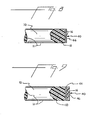
- Fig. 8 shows a section of the optical fiber end of Fig. 5.
- Fig. 9 shows a section of an optical fiber end such as produced from the punched out film of Fig. 7.
- The desirable end capped optical fiber is attained by first coating a thin polyethylene terephthalate or similar
transparent film 46 approximately 0.0234 mm thick with ahardenable material 44 as in Fig. 6, drying this coating, and covering it with aprotective film layer 48 which allows thecomposite film 20 to be stored and transported in contact with itself.Film 20 containing thehardenable material 44 is pulled from astorage reel 24 through an energytransmissible hardening zone 32 on a film-support base 30. Aroller 26 strips theprotective film 48 before thefilm 20 reaches thehardening zone 32. Anoptical fiber 10 from a fiber optical cable is fed through anoptical fiber connector 14 and gripped by theconnector end 12. Theoptical fiber 10 with itscladding 11 surrounding its core is allowed to protrude approximately 1 mm from theend 12 of theconnector 14. Theoptical fiber end 16 has been previously cut or equivalently fractured substantially perpendicular to its axis. Theconnector 14 is mounted within ahousing 19 having amovable part 17 and afixed part 18. It is guided by mechanical or electrical means toward theenergy source 22 on the opposite side from thefilm support base 30. See Fig. 1. - In Fig. 2, the
end 16 of the optical fiber contacts thefilm strip 20 containing a thin coating of ahardenable material 44. Therough cut end 16 of theoptical fiber 10 is embedded within the hardenable layer on the surface of the film. The energy source such aslight source 22 is caused to impinge upon the roughcut fiber end 16 now containing thehardenable material 44, either by controlled electrical activation or by action ofshutter 34. The hardenable material thereafter hardens by virtue of exposure to the energy source. - The resulting, smooth, flat,. capped
optical fiber end 40 containing thehardenable layer 44 in a hardened condition is shown in Figs. 3, 5 and 8. - The
hardenable layer 44 should be sufficiently thick to fill the surface depressions on therough cut end 16 of the optical fiber, which depressions typically range in maximum depth from 2 µm to 20 µm. The hardenable layer, however, should not be so thick that the axial separation it introduces between two juxtaposed fiber ends increases the optical flux loss at this juncture by more than approximately 2 db. This maximum thickness of the hardenable layer depends on several parameters of the optical fiber to be end-capped, but most strongly on its core diameter and its numerical aperture (NA), which latter is defined as the sine of the angle at which the far-field angular distribution of light intensity exiting the fiber fails to 10% of its axial value. It has been found experimentally that a useful approximation for this maximum thickness is provided by the relationship - Maximum ThicknessS0.45xCore Diameter/NA.
- The remaining film strip, after removal of the hardenable layer, continues onto
reel 28. Another connector containing a rough cut optical fiber end can be inserted into thehousing 19 and the process continued as thefilm strip 20 moves across thesupport 30. - The same process can be carried out substituting a
heat source 38 for thelight source 22 and hardenable materials sensitive to heat. - In an alternate embodiment the
film strip 20 is punched out at the point of impact with theoptical fiber end 16 so that the cappedoptical fiber end 40 has a coat ofhardenable material 44 and thethin film 46. See Figs. 7 and 9. Thethin film 46 can be left on the fiber end or can be subsequentlv removed. - In the preferred embodiment of this process, the
film 46 supporting thehardenable layer 44 is removed while the hardenable layer remains on said cappedfiber end 40 as shown in Fig. 3. - The optical fiber employed in this invention can be any of the glass or plastic, fibers employed in fiber optic communications, provided that the constituents of the hardenable layer do not dissolve or otherwise- physically or chemically attack the elements of the fiber.
- The thin film base can be any tight transmissible film capable of supporting a hardenable material. The preferred films are polyethylene terephthalate and polyethylene.
- The hardenable layer must be light transmissible in the same wavelength band used to transmit information through the optical fiber and preferably is a photohardenable composition. Among suitable photohardenable compositions are: (1) those in which a photopolymerizable monomer is present, preferably in combination with a compatible binder or (2) those in which a photopolymerizable group attached to a polymer backbone becomes activated through
light source 22 and may then crosslink by acting with a similar group or other reactive sites on adjacent polymer chains. In the second group of suitable photopolymerizable systems, where the monomer or pendant photopolymerizable group is capable of addition polymerization, e.g., a vinyl monomer, the photopolymerized chain length may involve addition of many similar units initiated by a single photochemical event. Where only dimerization is involved, e.g., with benzophenone or cinnamoyl compounds, the average molecular weight of the photosensitive constituent can be, at best, only doubled by a single photochemical act. Where a photopolymerizable molecule has more than one reactive site, a crosslinked network can be produced. - If either a simple monomer or monomer-polymer composition has been used, the photosensitive layer preferably contains a free radical generating, addition polymerization initiator. Plasticizing agents as well as other known additives can be present in the photosensitive layer.
- Suitable free radical initiated, chain propagating, addition polymerizable, ethylenically unsaturated compounds for use in the monomer or monomer-polymer binder photopolymerizable layers are described in U.S. Patents 3,060,023, 3,261,686, 3,380,831 and 3,649,268. Polymers for use in the monomer-polymer system and preferred free radical generating addition polymerization in initiators are described in U.S. Patent 3,060,023. These patents are herein incorporated by reference.
- Photodimerizable materials useful in the invention are cinnamic acid esters of high molecular weight polyols, polymers having chalcone and benzophenone type groups, and others disclosed in Chapter 4 of "Light Sensitive Systems" by Jaromir Kosar, published by John Wiley and Sons, Inc., N.Y., -165. Photopolymerizable materials capable of crosslinking with more than one adjacent polymeric chain to form a network are described in U.S. Patents 3,418,295 and 3,469,982. These patents are also herein incorporated by reference.
- Preferred free radical generating addition polymerization initiators. activatable by actinic radiation, e.g., ultraviolet invisible radiation are listed in U.S. Patent 3,060,023 and the other patents referred to above.
- Suitable plasticizers include: dialkyl phthalates, polyoxyethylene(4)monolaurylether, polyethylene glycol, triethylene glycol diacetate, alkyl phosphates, etc.
- In addition to the photohardenable systems described above, the hardenable layer may be one which is thermally curable as shown in Fig. 4. Such thermally curable layers may include thermosetting layers such as clear epoxy resins which harden either at room temperature or upon exposure to elevated temperatures and in which such hardening is an irreversible setting process. Either one- or two-part epoxy resin systems may be employed, and when a two-part system is used, the components may be premixed and then applied as a layer, or two separate layers may be applied in a sequential application.
- Thermally polymerizable layers may be used in which, rather than the free radical generating addition polymerization initiators activatable by actinic radiation referred to above, a thermally activatable initiator such as benzoyl peroxide may be used in which case hardening proceeds via polymerization of the monomers initiated by heating.
- The end caps may also be produced using hardenable layers which exhibit thermoplastic properties. By thermoplastic properties I mean a layer which can be softened by heating to a temperature above room temperature and then hardened by recooling to room temperature. Such layers may be polymeric or nonpolymeric, such as paraffin, which can be softened by heating to 50 to 60°C and hardened by recooling to room temperature.
- The preferred hardenable materials are photopolymers described in U.S. Patent 3,649,268 and in Example II below.
- The following procedure is followed in all of the Examples. First, a thin layer of a hardenable composition is coated on a transparent supporting base such as a thin sheet of polyethylene terephthalate film base. After drying, the coating is optionally covered with a protective layer, such as a thin sheet of polyethylene, to facilitate temporary storage.
- Secondly, a 50-meter length of a fiber optic cable having 200/pm silica core and a 600/,um hard plastic cladding, such as Pifax® S-120,
type 30, commercially available from E. I. du Pont de Nemours and Company, is connected between a light-emitting diode (LED) emitting at a wavelength of 820 nm and a silicon PIN diode located so as to detect all of the light exiting the fiber, The flux transmitted through this unbroken fiber is measured and recorded. - Thirdly, the fiber is then cut approximately two meters from the detecting PIN diode end. The cut ends are rough-ground perpendicular to the fiber axis using 40/,um abrasive particles. The ends are cleaned with an air blast to remove lingering ground particles or dust.
- Fourthly, the protective layer, if employed, is removed from the coated hardenable layer and the fiber end is brought into contact with the coated hardenable layer and pressed therein. While the fiber end is thus embedded, the layer is hardened, as described in the specific examples below.
- Following hardening, the now capped ends are abutted in perfect alignment. The reconnected 50 meters of optical fiber again transmit flux between the LED and silicon PIN detector diode. This transmitted flux is measured and the ratio of flux transmitted through the two connected fiber sections to that transmitted through the unbroken fiber is determined. This ratio is then converted to decibels (db) by taking the negative of 10 times its logarithm and the resulting number used to indicate the power loss in the various end-capping methods. In all examples, the final values have been corrected for long term drift of the testing apparatus. In addition, the accuracy of the reported results is estimated to be within ±0.4 of the reported db value.
- The following materials and compositions, together with the described specific steps, demonstrate a wide variety of methods implementing the process of this invention.
- There is first selected a 0.0008 inch (0.020 mm) thick strip of positive working Cromalin@ 4/C proofing film, commercially available from E. I. du Pont de Nemours and Company and which comprises a polyethylene terephthalate film base coated with a photohardenable, photopolymerizable layer. A fiber, its end cut and prepared as disclosed above, is then embedded into the photohardenable layer and exposed to UV radiation through the film base using a mercury short-arc lamp as source. The hardenable composition hardens in the area exposed to the UV radiation in the absence of a continuing supply of oxygen. The only such area is the area in contact with the fiber end. The fiber end serves as a seal preventing atmospheric oxygen from reaching the photohardenable layer from one side, and the supporting base prevents oxygen from reaching the photohardenable layer from the other side.
- Following hardening of the photopolymerizable layer, the transmission loss with the film base still attached to the end of the fiber is measured as disclosed above and is found to be 0.9 db.
- A photopolymerizable composition comprising:

- Using the same procedure as for Example 1 except that the UV radiation is obtained from a xenon flash tube, a loss of 2.4 db is measured. Following this measurement, the polyethylene terephthalate film is removed from the fiber end leaving adhered onto the fiber end the photopolymerized, hardened layer. Loss measurements are repeated and the loss is found to be 1.6 db.
- A photocrosslinkable hardenable layer is. used such as KPR photoresist available commercially from the Eastman Kodak Company, in which hardening proceeds through the exposure to UV radiation and the subsequent crosslinking of polyvinyl alcohol/polyvinyl cinnamate copolymer chains. This layer. supported on a polyethylene base 0.001 inch (0.025 mm) thick, is used as in Example 1 above to provide a cap at the end of a fiber optic cable. Measurements indicate a 1.8 db loss with the film base attached to the end of the fiber and 1.3 db loss with the film base removed.
- A thermosetting layer is coated on a thin film sheet of polyethylene 0.0254 mm thick. The thermosetting layer comprises a commercially available two-part epoxy resin and hardener adhesive available through Tra-Con, Inc. of Medford, Mass. under the trade name Tra-Bond 2101, having a specific gravity of 1.20 and a viscosity after mixing of 190 poise at 25°C. It is mixed in proportions by weight of 25 parts of hardener to 100 parts of resin. The fiber optic end is embedded in the hardenable layer and the layer allowed to set for a period of 18 hours at 20―25°C. Transmission loss is again measured as described above in Example 2, first with the polyethylene base left on the fiber, and then with the base removed and the set adhesive layer alone forming a cap to the fiber. In both instances, loss is measured as 1.0 db.
- A thermally polymerizable layer is used. as a hardenable layer which comprises the composition shown in Example 2 above, but in which the 2,2'-(o-chforophenyl)-4,4',5,5'-tetraphenylbimidazole and Michler's ketone are replaced by 6.5 g of a thermally sensitive initiator, benzoyl peroxide. The resulting composition is coated on polyethylene terephthalate base 0.00092 inch (.0234 mm) thick, and the fiber end is embedded therein. Following exposure to heat at 70° C for 60 min., whereby polymerization hardens the layer, transmission loss is measured as 1.7 db both with and without the film base present.
- A coating composition providing a thermoplastic layer comprising a mixture of an ethylene/vinyl acetate copolymer, ElvaX@ 210, available commercially through E. I. du Pont de Nemours and Company and a tackifying resin, Escorez® 5280, an aliphatic hydrocarbon tackifying resin made by Exxon Corp., in a 35/65 ratio by weight is coated on a 0.001 inch (0.00254 mm) polyethylene base. This composition is hard at normal room temperatures but may be softened by heating to 80-1200C. The layer is softened by heating to 80°C, a temperature low enough to not affect either glass fiber or the protective cladding, and while soft, the glass fiber end is embedded therein. It is then cooled to room temperature (20°C), whereupon the thermoplastic layer becomes hard. As in Example 1 above, transmission loss is measured with the polyethylene film present as part of the end cap and recorded as 1.8 db.
- The same composition is then coated onto a sheet of polyethylene terephthalate base, 0.00092 inches (0.0234 mm) and the procedure is repeated. Loss is measured as 1.6 db. The film base is removed by peeling it off from the fiber end, leaving behind the hardened layer. The light loss is measured as 1.1 db.
- A nonpolymeric hardenable layer, paraffin, which can be softened by heating to a temperature of about 50° to 60°C and which is hard at room temperature is coated on a polyethylene terephthalate base as in Example 6. Following the same procedure as in Example 6, but heating it only to about 60°C, loss measurements are recorded. as 0.8 db with the film base as part of the end cap and 0.6 db with the film base removed.
for plastic clad silica fiber with NA=0.38 and a core diameter of 200 µm, this maximum thickness is 240 jam.
Claims (17)
Priority Applications (1)
| Application Number | Priority Date | Filing Date | Title |
|---|---|---|---|
| AT82200185T ATE9740T1 (en) | 1981-02-17 | 1982-02-16 | FINISHING FOR AN OPTICAL FIBER. |
Applications Claiming Priority (2)
| Application Number | Priority Date | Filing Date | Title |
|---|---|---|---|
| US06/235,036 US4436366A (en) | 1981-02-17 | 1981-02-17 | End capping an optical fiber |
| US235036 | 1981-02-17 |
Publications (2)
| Publication Number | Publication Date |
|---|---|
| EP0058461A1 EP0058461A1 (en) | 1982-08-25 |
| EP0058461B1 true EP0058461B1 (en) | 1984-10-03 |
Family
ID=22883814
Family Applications (1)
| Application Number | Title | Priority Date | Filing Date |
|---|---|---|---|
| EP82200185A Expired EP0058461B1 (en) | 1981-02-17 | 1982-02-16 | End capping an optical fiber |
Country Status (14)
| Country | Link |
|---|---|
| US (1) | US4436366A (en) |
| EP (1) | EP0058461B1 (en) |
| JP (1) | JPS57188008A (en) |
| KR (1) | KR880001113B1 (en) |
| AT (1) | ATE9740T1 (en) |
| BR (1) | BR8200744A (en) |
| CA (1) | CA1174496A (en) |
| DE (1) | DE3260858D1 (en) |
| DK (1) | DK159026C (en) |
| ES (1) | ES8304670A1 (en) |
| HK (1) | HK13886A (en) |
| MX (1) | MX159333A (en) |
| NO (1) | NO165130C (en) |
| SG (1) | SG99285G (en) |
Cited By (1)
| Publication number | Priority date | Publication date | Assignee | Title |
|---|---|---|---|---|
| DE4012747A1 (en) * | 1990-04-21 | 1991-10-24 | Bodenseewerk Geraetetech | METHOD FOR THE PRODUCTION OF FINE OPTICAL FRONT SURFACES ON WAVE LADDERS |
Families Citing this family (31)
| Publication number | Priority date | Publication date | Assignee | Title |
|---|---|---|---|---|
| JPS608481B2 (en) * | 1980-09-01 | 1985-03-04 | 松下電器産業株式会社 | Optical fiber connection method |
| US4648688A (en) * | 1982-05-24 | 1987-03-10 | Amp Incorporated | Connector for fiber optic member including polishing fixture and method of terminating same |
| US4510005A (en) * | 1982-09-28 | 1985-04-09 | Allied Corporation | Method and apparatus for reshaping and polishing an end face of an optical fiber |
| NL8303251A (en) * | 1983-09-22 | 1985-04-16 | Philips Nv | METHOD FOR OPTICALLY CONNECTING A LIGHT GUIDE TO AN ELECTROOPTIC DEVICE |
| JPS61500457A (en) * | 1983-11-15 | 1986-03-13 | レイコム システムズ インコ−ポレ−テツド | optical fiber coupling device |
| US4783137A (en) * | 1983-11-15 | 1988-11-08 | Kosman Karel J | Fiber optic coupling system |
| FR2567319B1 (en) * | 1984-07-03 | 1986-12-12 | Labo Electronique Physique | INCLUDED CATHODOLUMINESCENT SCREEN WITH RESTORED CAVITIES AND VISUALIZATION TUBE USING SUCH A SCREEN |
| USRE34005E (en) * | 1985-11-20 | 1992-07-21 | Raychem Corporation | Contact for terminating an optical fiber |
| US4790622A (en) * | 1985-11-20 | 1988-12-13 | Raychem Corp. | Contact for terminating an optical fiber |
| JPS6338905A (en) * | 1986-08-04 | 1988-02-19 | Toray Ind Inc | Optical fiber having coating film |
| US5113787A (en) * | 1988-05-20 | 1992-05-19 | Raychem Corp. | Optical fiber termination coating dispenser |
| JPH02264907A (en) * | 1989-04-06 | 1990-10-29 | Nippon Telegr & Teleph Corp <Ntt> | Cleaning implement for optical connector |
| US5099761A (en) * | 1991-01-28 | 1992-03-31 | The United States Of America As Represented By The Secretary Of The Army | Laser actuated thru-bulkhead initiator |
| US5400424A (en) * | 1993-12-17 | 1995-03-21 | Williams; Charles M. | Module for a non-reflective fiber optic display screen |
| US5825955A (en) * | 1997-02-05 | 1998-10-20 | Molex Incorporated | Fiber optic diversion connector |
| DE19712950C2 (en) * | 1997-03-27 | 2002-11-07 | Deutsche Telekom Ag | Optical connection |
| US5883995A (en) | 1997-05-20 | 1999-03-16 | Adc Telecommunications, Inc. | Fiber connector and adapter |
| DE19737498C2 (en) * | 1997-08-28 | 2002-09-12 | Deutsche Telekom Ag | Optical connection |
| US6415471B1 (en) | 1999-06-30 | 2002-07-09 | Corning Cable Systems Llc | Device for cleaning mechanism for fiber optic connectors |
| US6619854B2 (en) | 2001-01-31 | 2003-09-16 | Teradyne, Inc. | Techniques for cleaning an optical interface of an optical connection system |
| US6547444B2 (en) * | 2001-01-31 | 2003-04-15 | Teradyne, Inc. | Techniques for selectively exposing and protecting an optical interface using film |
| US6839935B2 (en) * | 2002-05-29 | 2005-01-11 | Teradyne, Inc. | Methods and apparatus for cleaning optical connectors |
| US6762941B2 (en) | 2002-07-15 | 2004-07-13 | Teradyne, Inc. | Techniques for connecting a set of connecting elements using an improved latching apparatus |
| US6832858B2 (en) * | 2002-09-13 | 2004-12-21 | Teradyne, Inc. | Techniques for forming fiber optic connections in a modularized manner |
| US7042562B2 (en) * | 2002-12-26 | 2006-05-09 | Amphenol Corp. | Systems and methods for inspecting an optical interface |
| DE10323087B4 (en) * | 2003-05-16 | 2006-12-21 | Frank Optic Products Gmbh Optische Technologien | Method and device for coating the end faces of prefabricated optical fibers |
| JP2008292710A (en) * | 2007-05-23 | 2008-12-04 | Sumitomo Electric Ind Ltd | Optical connector and assembling method thereof |
| DE102007040083B4 (en) * | 2007-08-24 | 2011-06-22 | robatex GmbH, 52222 | Light-conducting component and, device and method for its production |
| US9334378B2 (en) * | 2008-01-11 | 2016-05-10 | The Boeing Company | Distortion resistant transparent reinforcing fibers for use in transparent reinforced composites |
| JP5228037B2 (en) * | 2008-03-31 | 2013-07-03 | 株式会社巴川製紙所 | Rubber member, adhesive connection member and optical connection structure |
| JOP20190083A1 (en) | 2008-06-04 | 2017-06-16 | Amgen Inc | Fgf21 mutant fusion polypeptides and uses thereof |
Family Cites Families (10)
| Publication number | Priority date | Publication date | Assignee | Title |
|---|---|---|---|---|
| US3455625A (en) | 1966-06-23 | 1969-07-15 | Bausch & Lomb | Optical fiber bundle coupling system |
| JPS525857B2 (en) | 1972-10-23 | 1977-02-17 | ||
| US3864019A (en) | 1973-11-15 | 1975-02-04 | Bell Telephone Labor Inc | Optical film-fiber coupler |
| US4290667A (en) | 1976-02-03 | 1981-09-22 | International Standard Electric Corporation | Optical fibre terminations and connectors |
| US4099837A (en) | 1976-05-26 | 1978-07-11 | Bell Telephone Laboratories, Incorporated | Coating of fiber lightguides with UV cured polymerization products |
| DE2638110C3 (en) | 1976-08-20 | 1981-05-21 | Siemens AG, 1000 Berlin und 8000 München | Capping for optical cables |
| GB1558689A (en) * | 1977-12-06 | 1980-01-09 | Standard Telephones Cables Ltd | Reduction of reflection at fibre optic ends |
| CA1154287A (en) * | 1979-02-26 | 1983-09-27 | Joseph E. Gervay | Dry-developing photosensitive dry film resist |
| US4221461A (en) * | 1979-05-17 | 1980-09-09 | Bell Telephone Laboratories, Incorporated | Fiber connector gap material |
| US4286043A (en) * | 1980-05-21 | 1981-08-25 | E. I. Du Pont De Nemours And Company | Negative-working dry peel apart photopolymer element with polyvinylformal binder |
-
1981
- 1981-02-17 US US06/235,036 patent/US4436366A/en not_active Expired - Lifetime
-
1982
- 1982-02-12 BR BR8200744A patent/BR8200744A/en unknown
- 1982-02-16 JP JP57022162A patent/JPS57188008A/en active Pending
- 1982-02-16 EP EP82200185A patent/EP0058461B1/en not_active Expired
- 1982-02-16 AT AT82200185T patent/ATE9740T1/en not_active IP Right Cessation
- 1982-02-16 KR KR8200677A patent/KR880001113B1/en active
- 1982-02-16 NO NO820469A patent/NO165130C/en unknown
- 1982-02-16 MX MX191420A patent/MX159333A/en unknown
- 1982-02-16 DE DE8282200185T patent/DE3260858D1/en not_active Expired
- 1982-02-16 CA CA000396353A patent/CA1174496A/en not_active Expired
- 1982-02-16 ES ES509660A patent/ES8304670A1/en not_active Expired
- 1982-02-16 DK DK067482A patent/DK159026C/en not_active Application Discontinuation
-
1985
- 1985-12-27 SG SG992/85A patent/SG99285G/en unknown
-
1986
- 1986-02-27 HK HK138/86A patent/HK13886A/en unknown
Cited By (1)
| Publication number | Priority date | Publication date | Assignee | Title |
|---|---|---|---|---|
| DE4012747A1 (en) * | 1990-04-21 | 1991-10-24 | Bodenseewerk Geraetetech | METHOD FOR THE PRODUCTION OF FINE OPTICAL FRONT SURFACES ON WAVE LADDERS |
Also Published As
| Publication number | Publication date |
|---|---|
| US4436366A (en) | 1984-03-13 |
| NO165130C (en) | 1990-12-27 |
| SG99285G (en) | 1986-07-18 |
| ES509660A0 (en) | 1983-03-01 |
| HK13886A (en) | 1986-03-07 |
| EP0058461A1 (en) | 1982-08-25 |
| KR880001113B1 (en) | 1988-06-29 |
| ATE9740T1 (en) | 1984-10-15 |
| BR8200744A (en) | 1982-12-21 |
| DK159026B (en) | 1990-08-20 |
| JPS57188008A (en) | 1982-11-18 |
| KR830009495A (en) | 1983-12-21 |
| ES8304670A1 (en) | 1983-03-01 |
| CA1174496A (en) | 1984-09-18 |
| NO165130B (en) | 1990-09-17 |
| DE3260858D1 (en) | 1984-11-08 |
| MX159333A (en) | 1989-05-17 |
| NO820469L (en) | 1982-08-18 |
| DK159026C (en) | 1991-01-28 |
| DK67482A (en) | 1982-08-18 |
Similar Documents
| Publication | Publication Date | Title |
|---|---|---|
| EP0058461B1 (en) | End capping an optical fiber | |
| JP2704047B2 (en) | Method of fabricating an array of tapered photopolymerized waveguides | |
| JP3836127B2 (en) | Polymer microstructures that facilitate the coupling of optical fibers to waveguides | |
| JP4138892B2 (en) | Low stress optical waveguide having conformal cladding and fixing member for precision optical connection | |
| KR101411153B1 (en) | Curable Compositions for Optical Articles | |
| US6335149B1 (en) | High performance acrylate materials for optical interconnects | |
| US4425375A (en) | End capping an optical fiber | |
| JP4535309B2 (en) | Optical recording material | |
| JPH08512146A (en) | Thermally stable photopolymer composition and optical transmission device | |
| KR101660056B1 (en) | Method for provisional fixing/release of member and adhesive for provisional fixing suitable therefor | |
| JPH075693A (en) | Method and equipment for providing patternized relief of hardened photoresist on flat substrate surface | |
| EP3513227B1 (en) | High refractive index nanocomposites | |
| EP0972216B1 (en) | Clad optic fiber | |
| CN103459538A (en) | Optical stack comprising adhesive | |
| KR100265105B1 (en) | Curable composition for use in optical fiber cladding and optical fiber equipped therewith | |
| JP2006058831A (en) | Photosensitive resin composition for optical waveguide and optical waveguide | |
| CA2177215C (en) | Use of ultraviolet-curable adhesive in preparation of optical fiber dispensers | |
| GB2047913A (en) | Coupling of light guides and electro-optical devices | |
| CA2118104A1 (en) | Radiation curable compositions and their use for coating a substrate | |
| Krchnavek et al. | Photo-polymerized acrylic waveguides for optical interconnects | |
| JP2534994B2 (en) | Polymer optical waveguide and method for manufacturing the same | |
| US20070041697A1 (en) | Optical component | |
| KR0142676B1 (en) | Polymer claddings for optical fibre waveguides | |
| JPS6327830A (en) | Fluorescent photocurable composition | |
| JP2023055538A (en) | Optical element, optical element production method, resin composition, optical equipment, and imaging device |
Legal Events
| Date | Code | Title | Description |
|---|---|---|---|
| PUAI | Public reference made under article 153(3) epc to a published international application that has entered the european phase |
Free format text: ORIGINAL CODE: 0009012 |
|
| AK | Designated contracting states |
Designated state(s): AT BE CH DE FR GB IT LU NL SE |
|
| 17P | Request for examination filed |
Effective date: 19820903 |
|
| ITF | It: translation for a ep patent filed |
Owner name: ING. C. GREGORJ S.P.A. |
|
| GRAA | (expected) grant |
Free format text: ORIGINAL CODE: 0009210 |
|
| AK | Designated contracting states |
Designated state(s): AT BE CH DE FR GB IT LI LU NL SE |
|
| REF | Corresponds to: |
Ref document number: 9740 Country of ref document: AT Date of ref document: 19841015 Kind code of ref document: T |
|
| REF | Corresponds to: |
Ref document number: 3260858 Country of ref document: DE Date of ref document: 19841108 |
|
| ET | Fr: translation filed | ||
| PG25 | Lapsed in a contracting state [announced via postgrant information from national office to epo] |
Ref country code: LU Free format text: LAPSE BECAUSE OF NON-PAYMENT OF DUE FEES Effective date: 19850228 |
|
| PLBE | No opposition filed within time limit |
Free format text: ORIGINAL CODE: 0009261 |
|
| STAA | Information on the status of an ep patent application or granted ep patent |
Free format text: STATUS: NO OPPOSITION FILED WITHIN TIME LIMIT |
|
| 26N | No opposition filed | ||
| PGFP | Annual fee paid to national office [announced via postgrant information from national office to epo] |
Ref country code: FR Payment date: 19891130 Year of fee payment: 9 |
|
| PGFP | Annual fee paid to national office [announced via postgrant information from national office to epo] |
Ref country code: SE Payment date: 19891205 Year of fee payment: 9 |
|
| PGFP | Annual fee paid to national office [announced via postgrant information from national office to epo] |
Ref country code: CH Payment date: 19891206 Year of fee payment: 9 |
|
| PGFP | Annual fee paid to national office [announced via postgrant information from national office to epo] |
Ref country code: DE Payment date: 19891207 Year of fee payment: 9 |
|
| PGFP | Annual fee paid to national office [announced via postgrant information from national office to epo] |
Ref country code: AT Payment date: 19891228 Year of fee payment: 9 |
|
| PGFP | Annual fee paid to national office [announced via postgrant information from national office to epo] |
Ref country code: BE Payment date: 19900110 Year of fee payment: 9 |
|
| PGFP | Annual fee paid to national office [announced via postgrant information from national office to epo] |
Ref country code: LU Payment date: 19900124 Year of fee payment: 9 |
|
| PGFP | Annual fee paid to national office [announced via postgrant information from national office to epo] |
Ref country code: GB Payment date: 19900131 Year of fee payment: 9 |
|
| ITTA | It: last paid annual fee | ||
| PGFP | Annual fee paid to national office [announced via postgrant information from national office to epo] |
Ref country code: NL Payment date: 19900228 Year of fee payment: 9 |
|
| PG25 | Lapsed in a contracting state [announced via postgrant information from national office to epo] |
Ref country code: AT Effective date: 19910216 Ref country code: GB Effective date: 19910216 |
|
| PG25 | Lapsed in a contracting state [announced via postgrant information from national office to epo] |
Ref country code: SE Effective date: 19910217 |
|
| PG25 | Lapsed in a contracting state [announced via postgrant information from national office to epo] |
Ref country code: LI Effective date: 19910228 Ref country code: CH Effective date: 19910228 Ref country code: BE Effective date: 19910228 |
|
| PG25 | Lapsed in a contracting state [announced via postgrant information from national office to epo] |
Ref country code: NL Effective date: 19910901 |
|
| GBPC | Gb: european patent ceased through non-payment of renewal fee | ||
| NLV4 | Nl: lapsed or anulled due to non-payment of the annual fee | ||
| PG25 | Lapsed in a contracting state [announced via postgrant information from national office to epo] |
Ref country code: FR Effective date: 19911031 |
|
| REG | Reference to a national code |
Ref country code: CH Ref legal event code: PL |
|
| PG25 | Lapsed in a contracting state [announced via postgrant information from national office to epo] |
Ref country code: DE Effective date: 19911101 |
|
| REG | Reference to a national code |
Ref country code: FR Ref legal event code: ST |
|
| EUG | Se: european patent has lapsed |
Ref document number: 82200185.5 Effective date: 19911008 |