EP0058052A2 - Exerciser device - Google Patents
Exerciser device Download PDFInfo
- Publication number
- EP0058052A2 EP0058052A2 EP82300558A EP82300558A EP0058052A2 EP 0058052 A2 EP0058052 A2 EP 0058052A2 EP 82300558 A EP82300558 A EP 82300558A EP 82300558 A EP82300558 A EP 82300558A EP 0058052 A2 EP0058052 A2 EP 0058052A2
- Authority
- EP
- European Patent Office
- Prior art keywords
- rotatable member
- brake
- friction areas
- low friction
- drum
- Prior art date
- Legal status (The legal status is an assumption and is not a legal conclusion. Google has not performed a legal analysis and makes no representation as to the accuracy of the status listed.)
- Withdrawn
Links
Images
Classifications
-
- A—HUMAN NECESSITIES
- A63—SPORTS; GAMES; AMUSEMENTS
- A63B—APPARATUS FOR PHYSICAL TRAINING, GYMNASTICS, SWIMMING, CLIMBING, OR FENCING; BALL GAMES; TRAINING EQUIPMENT
- A63B21/00—Exercising apparatus for developing or strengthening the muscles or joints of the body by working against a counterforce, with or without measuring devices
- A63B21/00181—Exercising apparatus for developing or strengthening the muscles or joints of the body by working against a counterforce, with or without measuring devices comprising additional means assisting the user to overcome part of the resisting force, i.e. assisted-active exercising
-
- A—HUMAN NECESSITIES
- A63—SPORTS; GAMES; AMUSEMENTS
- A63B—APPARATUS FOR PHYSICAL TRAINING, GYMNASTICS, SWIMMING, CLIMBING, OR FENCING; BALL GAMES; TRAINING EQUIPMENT
- A63B21/00—Exercising apparatus for developing or strengthening the muscles or joints of the body by working against a counterforce, with or without measuring devices
- A63B21/00058—Mechanical means for varying the resistance
- A63B21/00069—Setting or adjusting the resistance level; Compensating for a preload prior to use, e.g. changing length of resistance or adjusting a valve
-
- A—HUMAN NECESSITIES
- A63—SPORTS; GAMES; AMUSEMENTS
- A63B—APPARATUS FOR PHYSICAL TRAINING, GYMNASTICS, SWIMMING, CLIMBING, OR FENCING; BALL GAMES; TRAINING EQUIPMENT
- A63B21/00—Exercising apparatus for developing or strengthening the muscles or joints of the body by working against a counterforce, with or without measuring devices
- A63B21/012—Exercising apparatus for developing or strengthening the muscles or joints of the body by working against a counterforce, with or without measuring devices using frictional force-resisters
- A63B21/015—Exercising apparatus for developing or strengthening the muscles or joints of the body by working against a counterforce, with or without measuring devices using frictional force-resisters including rotating or oscillating elements rubbing against fixed elements
-
- A—HUMAN NECESSITIES
- A63—SPORTS; GAMES; AMUSEMENTS
- A63B—APPARATUS FOR PHYSICAL TRAINING, GYMNASTICS, SWIMMING, CLIMBING, OR FENCING; BALL GAMES; TRAINING EQUIPMENT
- A63B22/00—Exercising apparatus specially adapted for conditioning the cardio-vascular system, for training agility or co-ordination of movements
- A63B22/0002—Exercising apparatus specially adapted for conditioning the cardio-vascular system, for training agility or co-ordination of movements involving an exercising of arms
- A63B22/0005—Exercising apparatus specially adapted for conditioning the cardio-vascular system, for training agility or co-ordination of movements involving an exercising of arms with particular movement of the arms provided by handles moving otherwise than pivoting about a horizontal axis parallel to the body-symmetrical-plane
-
- A—HUMAN NECESSITIES
- A63—SPORTS; GAMES; AMUSEMENTS
- A63B—APPARATUS FOR PHYSICAL TRAINING, GYMNASTICS, SWIMMING, CLIMBING, OR FENCING; BALL GAMES; TRAINING EQUIPMENT
- A63B22/00—Exercising apparatus specially adapted for conditioning the cardio-vascular system, for training agility or co-ordination of movements
- A63B22/0002—Exercising apparatus specially adapted for conditioning the cardio-vascular system, for training agility or co-ordination of movements involving an exercising of arms
- A63B22/0007—Exercising apparatus specially adapted for conditioning the cardio-vascular system, for training agility or co-ordination of movements involving an exercising of arms by alternatively exercising arms or legs, e.g. with a single set of support elements driven either by the upper or the lower limbs
-
- A—HUMAN NECESSITIES
- A63—SPORTS; GAMES; AMUSEMENTS
- A63B—APPARATUS FOR PHYSICAL TRAINING, GYMNASTICS, SWIMMING, CLIMBING, OR FENCING; BALL GAMES; TRAINING EQUIPMENT
- A63B21/00—Exercising apparatus for developing or strengthening the muscles or joints of the body by working against a counterforce, with or without measuring devices
- A63B21/22—Resisting devices with rotary bodies
- A63B21/225—Resisting devices with rotary bodies with flywheels
-
- A—HUMAN NECESSITIES
- A63—SPORTS; GAMES; AMUSEMENTS
- A63B—APPARATUS FOR PHYSICAL TRAINING, GYMNASTICS, SWIMMING, CLIMBING, OR FENCING; BALL GAMES; TRAINING EQUIPMENT
- A63B22/00—Exercising apparatus specially adapted for conditioning the cardio-vascular system, for training agility or co-ordination of movements
- A63B22/06—Exercising apparatus specially adapted for conditioning the cardio-vascular system, for training agility or co-ordination of movements with support elements performing a rotating cycling movement, i.e. a closed path movement
- A63B22/0605—Exercising apparatus specially adapted for conditioning the cardio-vascular system, for training agility or co-ordination of movements with support elements performing a rotating cycling movement, i.e. a closed path movement performing a circular movement, e.g. ergometers
-
- A—HUMAN NECESSITIES
- A63—SPORTS; GAMES; AMUSEMENTS
- A63B—APPARATUS FOR PHYSICAL TRAINING, GYMNASTICS, SWIMMING, CLIMBING, OR FENCING; BALL GAMES; TRAINING EQUIPMENT
- A63B23/00—Exercising apparatus specially adapted for particular parts of the body
- A63B23/035—Exercising apparatus specially adapted for particular parts of the body for limbs, i.e. upper or lower limbs, e.g. simultaneously
- A63B23/04—Exercising apparatus specially adapted for particular parts of the body for limbs, i.e. upper or lower limbs, e.g. simultaneously for lower limbs
- A63B23/0476—Exercising apparatus specially adapted for particular parts of the body for limbs, i.e. upper or lower limbs, e.g. simultaneously for lower limbs by rotating cycling movement
Definitions
- This invention relates to exerciser devices of the kind in which a shaft is rotated by a pair of pedal cranks or the like.
- the pedals may be arranged to be foot operated as in a bicycle, or hand rotated.
- the shaft may be braked or it may be arranged to drive a braked element, and the brake may be adjustable so as to vary the work done and hence the amount of exercise obtained.
- a problem with devices of this kind is that in converting near straight line motion ( of the user's arms or legs ) into rotary motion, the drive is most inefficient at two diametrically opposed points which it is convenient to call top dead centre (TDC) and bottom dead centre (BDC), although they are only vertically aligned in certain circumstances. If the brake is set to require considerable effort to turn the pedals, it may be difficult or even impossible to start the rotary motion if the pedals are left in the TDC and BDC positions, or the device may stall at such positions.
- a relatively massive flywheel can minimise stalling, and various means are theoretically possible to ensure low resistance to turning until a minimum rotational speed is achieved, but all of these possibilities tend to be relatively expensive.
- the object of the invention is to solve the problem in an inexpensive way.
- an exerciser device comprises a rotatable member which is braked, and which has at TDC and BDC positions ( as hereinbefore defined ) low friction areas for engagement by the brake.
- the rotatable member may be a brake drum engaged by an externally contracting brake shoe, and the brake drum may be a metal casting with inset pads of plastics material.
- the plastics material is not necessarily one with an ultra low coefficient of friction such as polytetrafluorethylene, and it is sufficient if its coefficient of friction is merely substantially less than that of the remainder of the drum, as might be the case for example by using a light alloy die casting for the drum with nylon inserts for the low friction areas.
- the brake shoe may have a lining of a conventional high friction material of the kind used for bicycle brakes or vehicle brakes, and it may be arranged to engage with the drum over a portion of its periphery, the brake pad having a generally rectangular shape.
- the length of the shoe and the corresponding dimensions of the low-friction material determine the effect obtained.
- a smooth transition can be achieved by shaping the friction surfaces so that during angular movement towards the BDC or TDC position a progressively greater proportion of the engaged areas involve the low friction material, and when the TDC or BDC position is passed, vice versa. This may be done with a circular pad of low-friction material which sweeps past the squared end of the brake shoe, but many other solutions are possible: for example a similar transitional effect can be obtained by using a brake pad which has shaped ends.
- an exercise “bicycle” comprises a main frame which forms a stand supporting handle bars and a saddle.
- the frame journals a spindle carrying a pair of oppositely directed pedal cranks each terminating in a corresponding pedal possibly provided with a toe clip.
- the spindle is fixed to a brake drur so that the latter rotates with the spindle as the pedal cranks are turned, and the brake shoe is mounted at one end of a lever pivoted between its ends on the frame, with the end opposite to that carrying the shoe connected to an adjuster device for example by cable.
- the braked rotatable member may be a disc instead of a drum and in this event a caliper-type brake device can be used in conjunction with the disc.
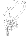
- the exerciser includes a frame having a seat tube 12 and rear legs 14 with a stablising crossbar 16.
- the frame will also include front legs with a stablising bar and handlebars as in a conventional cycle type exerciser.
- the frame journals a spindle 20 to which a pair of oppositely directed pedal cranks 22 are secured (only one crank 22 being shown in the drawing).
- the spindle 20 mounts a brake drum 24 and a flywheel 26 (shown in broken outline).
- a link 28 is pivoted to the frame at 30 and carries at its lower end a pivoted brake block 32 for frictional engagement with the periphery 34 of the drum 24.
- the force with which the block 32 bears against the surface 34 is governed by a tensioning cable 36 engaging the link adjacent its upper end.
- the cable 36 is conveniently connected to an adjustable tensioning device which is mounted so as to be readily accessible to the user when seated.
- the brake drum 24 is conveniently manufactured -as a casting with recesses for insertion of pads 38 of low friction material so that its periphery presents both low and higher frictional resistance areas to the block 32 as the drum rotates.
- the pads 38 are located at the previously mentioned TDC and BDC positions and they may be shaped as previously described so that the change in frictional resistance is progressive rather than abrupt.
Landscapes
- Health & Medical Sciences (AREA)
- General Health & Medical Sciences (AREA)
- Physical Education & Sports Medicine (AREA)
- Life Sciences & Earth Sciences (AREA)
- Biophysics (AREA)
- Orthopedic Medicine & Surgery (AREA)
- Cardiology (AREA)
- Vascular Medicine (AREA)
- Braking Arrangements (AREA)
Abstract
An exerciser device comprises a brake drum 24 and associated flywheel 26 which can be set into rotation by means of pedal cranks 22. A brake element 32 contacts the periphery of the brake drum 24 so as to exert resistance to turning of the brake drum. The braking surface of the drum 24 is provided with low friction areas in the form of plastics pads 38 which are cooperable with the brake block 32 at those positions corresponding to the top dead centre and bottom dead centre positions of the pedal cranks 22 thereby reducing the resistance to turning of the drum 24 and flywheel 26 as the pedal cranks 22 pass through such positions during each revolution.
Description
- This invention relates to exerciser devices of the kind in which a shaft is rotated by a pair of pedal cranks or the like. The pedals may be arranged to be foot operated as in a bicycle, or hand rotated.
- The shaft may be braked or it may be arranged to drive a braked element, and the brake may be adjustable so as to vary the work done and hence the amount of exercise obtained.
- A problem with devices of this kind is that in converting near straight line motion ( of the user's arms or legs ) into rotary motion, the drive is most inefficient at two diametrically opposed points which it is convenient to call top dead centre (TDC) and bottom dead centre (BDC), although they are only vertically aligned in certain circumstances. If the brake is set to require considerable effort to turn the pedals, it may be difficult or even impossible to start the rotary motion if the pedals are left in the TDC and BDC positions, or the device may stall at such positions.
- A relatively massive flywheel can minimise stalling, and various means are theoretically possible to ensure low resistance to turning until a minimum rotational speed is achieved, but all of these possibilities tend to be relatively expensive.
- The object of the invention is to solve the problem in an inexpensive way.
- According to the invention an exerciser device comprises a rotatable member which is braked, and which has at TDC and BDC positions ( as hereinbefore defined ) low friction areas for engagement by the brake.
- The rotatable member may be a brake drum engaged by an externally contracting brake shoe, and the brake drum may be a metal casting with inset pads of plastics material. The plastics material is not necessarily one with an ultra low coefficient of friction such as polytetrafluorethylene, and it is sufficient if its coefficient of friction is merely substantially less than that of the remainder of the drum, as might be the case for example by using a light alloy die casting for the drum with nylon inserts for the low friction areas.
- The brake shoe may have a lining of a conventional high friction material of the kind used for bicycle brakes or vehicle brakes, and it may be arranged to engage with the drum over a portion of its periphery, the brake pad having a generally rectangular shape. The length of the shoe and the corresponding dimensions of the low-friction material determine the effect obtained. Desirably there is a transition between the braking effect caused by engagement of the high friction brake pad with the medium friction metal of the drum and that caused by engagement of the same pad ( wholly ) with the low friction material, and vice versa, and equally desirably the full engagement between the low-friction material and the high friction material spans across the BDC and TDC positions.
- A smooth transition can be achieved by shaping the friction surfaces so that during angular movement towards the BDC or TDC position a progressively greater proportion of the engaged areas involve the low friction material, and when the TDC or BDC position is passed, vice versa. This may be done with a circular pad of low-friction material which sweeps past the squared end of the brake shoe, but many other solutions are possible: for example a similar transitional effect can be obtained by using a brake pad which has shaped ends.
- In a presently preferred embodiment of the invention, an exercise "bicycle" comprises a main frame which forms a stand supporting handle bars and a saddle. The frame journals a spindle carrying a pair of oppositely directed pedal cranks each terminating in a corresponding pedal possibly provided with a toe clip. The spindle is fixed to a brake drur so that the latter rotates with the spindle as the pedal cranks are turned, and the brake shoe is mounted at one end of a lever pivoted between its ends on the frame, with the end opposite to that carrying the shoe connected to an adjuster device for example by cable.
- In a modification, the braked rotatable member may be a disc instead of a drum and in this event a caliper-type brake device can be used in conjunction with the disc.
- To promote further understanding of the invention, one embodiment thereof will now be described by way of example only with reference to the accompanying drawing, the sole figure of which is a side view of part of a pedal exerciser.
- As shown, the exerciser includes a frame having a
seat tube 12 andrear legs 14 with astablising crossbar 16. Although not shown, the frame will also include front legs with a stablising bar and handlebars as in a conventional cycle type exerciser. The frame journals aspindle 20 to which a pair of oppositely directedpedal cranks 22 are secured (only onecrank 22 being shown in the drawing). Thespindle 20 mounts abrake drum 24 and a flywheel 26 (shown in broken outline). - A
link 28 is pivoted to the frame at 30 and carries at its lower end a pivotedbrake block 32 for frictional engagement with theperiphery 34 of thedrum 24. The force with which theblock 32 bears against thesurface 34 is governed by atensioning cable 36 engaging the link adjacent its upper end. Thecable 36 is conveniently connected to an adjustable tensioning device which is mounted so as to be readily accessible to the user when seated. - The
brake drum 24 is conveniently manufactured -as a casting with recesses for insertion of pads 38 of low friction material so that its periphery presents both low and higher frictional resistance areas to theblock 32 as the drum rotates. The pads 38 are located at the previously mentioned TDC and BDC positions and they may be shaped as previously described so that the change in frictional resistance is progressive rather than abrupt.
Claims (10)
1. An exerciser device comprising a rotatable member with means for braking the same, said rotatable member having, at TDC and BDC positions (as hereinbefore defined) thereof, low friction areas for engagement by the brake.
2. An exerciser device comprising a rotatable member, means to which a user can apply an effort in order to rotate said member and an adjustable brake element cooperable with said member to apply an adjustable resistance to rotation of the latter, characterised by means for automatically reducing the frictional resistance acting between the brake element and the rotatable member at predetermined positions during each revolution of the rotatable member.
3. A device as claimed in Claim 2 characterised in that said means comprises low friction areas forming part of that surface of the rotatable member against which the brake element bears, said low friction areas being separated, in the direction of rotation, by higher friction areas of.said surface and being provided at positions corresponding to the TDC and BDC positions (as hereinbefore defined) of the device.
4. A device as claimed in Claim 1 or Claim 3 in which the rotatable member is a brake drum having an annular surface around its periphery against which the brake element bears.
5. A device as claimed in Claim 1 or 3 in which the rotatable member is a brake disc having an annular surface on one or each of its faces against which the or a respective brake element bears.
6. A device as claimed in Claim 1, 3, 4 or 5 in which said rotable member has pads of plastics material inset therein to form low friction areas.
7. A device as claimed in Claim 6 in which the rotatable member is formed as a metal casting with said plastics pads inset therein.
8. A device as claimed in any one of Claims 1 to 7 in which the arrangement is such that the frictional resistance between the brake element and the rotatable member changes progressively between its higher and lower values as the rotatable member rotates.
9. A device as claimed in Claim 8 in which the reletive shapes of the brake element and the low friction areas are such as to cause said progressive change in frictional resistance.
10. A brake drum for an exerciser device, the brake drum having a braking surface to be contacted by a braking element, which surface includes a number of low friction areas spaced apart, in the designed direction of rotation of the brake drum, by higher friction areas.
Applications Claiming Priority (2)
| Application Number | Priority Date | Filing Date | Title |
|---|---|---|---|
| GB8103766 | 1981-02-06 | ||
| GB8103766 | 1981-02-06 |
Publications (2)
| Publication Number | Publication Date |
|---|---|
| EP0058052A2 true EP0058052A2 (en) | 1982-08-18 |
| EP0058052A3 EP0058052A3 (en) | 1982-09-22 |
Family
ID=10519517
Family Applications (1)
| Application Number | Title | Priority Date | Filing Date |
|---|---|---|---|
| EP82300558A Withdrawn EP0058052A3 (en) | 1981-02-06 | 1982-02-03 | Exerciser device |
Country Status (1)
| Country | Link |
|---|---|
| EP (1) | EP0058052A3 (en) |
Cited By (2)
| Publication number | Priority date | Publication date | Assignee | Title |
|---|---|---|---|---|
| WO1994016775A2 (en) * | 1993-01-27 | 1994-08-04 | Nordictrack, Inc. | Flywheel resistance mechanism for exercise equipment |
| FR2998021A1 (en) * | 2012-11-15 | 2014-05-16 | Aqua System Design | AQUATIC BIKE PEDAL |
Citations (2)
| Publication number | Priority date | Publication date | Assignee | Title |
|---|---|---|---|---|
| US3501142A (en) * | 1967-12-04 | 1970-03-17 | Monark Crescent Ab | Bicycle exerciser with cyclically varying resistance |
| DE3106448A1 (en) * | 1980-02-22 | 1981-12-24 | Shimano Industrial Co., Ltd., Sakai, Osaka | Exercise apparatus |
-
1982
- 1982-02-03 EP EP82300558A patent/EP0058052A3/en not_active Withdrawn
Patent Citations (2)
| Publication number | Priority date | Publication date | Assignee | Title |
|---|---|---|---|---|
| US3501142A (en) * | 1967-12-04 | 1970-03-17 | Monark Crescent Ab | Bicycle exerciser with cyclically varying resistance |
| DE3106448A1 (en) * | 1980-02-22 | 1981-12-24 | Shimano Industrial Co., Ltd., Sakai, Osaka | Exercise apparatus |
Cited By (5)
| Publication number | Priority date | Publication date | Assignee | Title |
|---|---|---|---|---|
| WO1994016775A2 (en) * | 1993-01-27 | 1994-08-04 | Nordictrack, Inc. | Flywheel resistance mechanism for exercise equipment |
| WO1994016775A3 (en) * | 1993-01-27 | 1994-09-15 | Nordictrack Inc | Flywheel resistance mechanism for exercise equipment |
| FR2998021A1 (en) * | 2012-11-15 | 2014-05-16 | Aqua System Design | AQUATIC BIKE PEDAL |
| EP2732853A1 (en) * | 2012-11-15 | 2014-05-21 | Societe Industrielle Radio Electrique Et Mecanique "Sirem" | Crankset for aquacycling bicycle |
| WO2014076212A3 (en) * | 2012-11-15 | 2014-07-10 | Societe Industrielle Radio Electrique Et Mecanique ''sirem'' | Aqua bike crankset |
Also Published As
| Publication number | Publication date |
|---|---|
| EP0058052A3 (en) | 1982-09-22 |
Similar Documents
| Publication | Publication Date | Title |
|---|---|---|
| US4007927A (en) | Inertial cycle exerciser | |
| US4955599A (en) | Exercise cycle with gear drive | |
| US3966201A (en) | Exercising machine | |
| US4441705A (en) | Exercising apparatus | |
| US3501142A (en) | Bicycle exerciser with cyclically varying resistance | |
| US4071235A (en) | Adjustable resistance exercising apparatus | |
| US5906563A (en) | Dual exercise bike | |
| US5520401A (en) | Step drive cycle | |
| US3758107A (en) | Bicycle-type exercising apparatus with eccentric mounting | |
| US20030098566A1 (en) | Lever operated foot pump scooter | |
| EP0058052A2 (en) | Exerciser device | |
| US3062329A (en) | Disc brake mechanism | |
| US4257588A (en) | Exercise bicycles | |
| US20030078140A1 (en) | Exercising machine having double-shaft type drive system with high speed ratio | |
| US6032969A (en) | Arm or leg actuated exercise apparatus | |
| GB2177221A (en) | Torque metering device for bicycle-type ergometer | |
| CN207466887U (en) | A kind of Motorcycle safety brake device | |
| JP2643494B2 (en) | Bicycle drive | |
| JPH074044Y2 (en) | Health device | |
| CN221905610U (en) | Resistance adjusting device for resistance wheel of body-building equipment | |
| CN2155906Y (en) | Health care cart | |
| CN2456774Y (en) | Scooter brake device | |
| US20040262878A1 (en) | Lever enhanced pedaling system | |
| SU600343A1 (en) | Shoe brake | |
| JPS632052Y2 (en) |
Legal Events
| Date | Code | Title | Description |
|---|---|---|---|
| PUAI | Public reference made under article 153(3) epc to a published international application that has entered the european phase |
Free format text: ORIGINAL CODE: 0009012 |
|
| PUAL | Search report despatched |
Free format text: ORIGINAL CODE: 0009013 |
|
| AK | Designated contracting states |
Designated state(s): AT BE CH DE FR GB IT LU NL SE |
|
| AK | Designated contracting states |
Designated state(s): AT BE CH DE FR GB IT LU NL SE |
|
| 17P | Request for examination filed |
Effective date: 19821203 |
|
| STAA | Information on the status of an ep patent application or granted ep patent |
Free format text: STATUS: THE APPLICATION IS DEEMED TO BE WITHDRAWN |
|
| 18D | Application deemed to be withdrawn |
Effective date: 19840901 |
|
| RIN1 | Information on inventor provided before grant (corrected) |
Inventor name: SMITH, ROGER MICHAEL |