EP0057949A1 - Pulse radar apparatus - Google Patents
Pulse radar apparatus Download PDFInfo
- Publication number
- EP0057949A1 EP0057949A1 EP82200075A EP82200075A EP0057949A1 EP 0057949 A1 EP0057949 A1 EP 0057949A1 EP 82200075 A EP82200075 A EP 82200075A EP 82200075 A EP82200075 A EP 82200075A EP 0057949 A1 EP0057949 A1 EP 0057949A1
- Authority
- EP
- European Patent Office
- Prior art keywords
- cluster
- cell
- trace
- target
- signals
- Prior art date
- Legal status (The legal status is an assumption and is not a legal conclusion. Google has not performed a legal analysis and makes no representation as to the accuracy of the status listed.)
- Granted
Links
Images

Classifications
-
- G—PHYSICS
- G01—MEASURING; TESTING
- G01S—RADIO DIRECTION-FINDING; RADIO NAVIGATION; DETERMINING DISTANCE OR VELOCITY BY USE OF RADIO WAVES; LOCATING OR PRESENCE-DETECTING BY USE OF THE REFLECTION OR RERADIATION OF RADIO WAVES; ANALOGOUS ARRANGEMENTS USING OTHER WAVES
- G01S13/00—Systems using the reflection or reradiation of radio waves, e.g. radar systems; Analogous systems using reflection or reradiation of waves whose nature or wavelength is irrelevant or unspecified
- G01S13/02—Systems using reflection of radio waves, e.g. primary radar systems; Analogous systems
- G01S13/06—Systems determining position data of a target
- G01S13/08—Systems for measuring distance only
- G01S13/10—Systems for measuring distance only using transmission of interrupted, pulse modulated waves
- G01S13/20—Systems for measuring distance only using transmission of interrupted, pulse modulated waves whereby multiple time-around echoes are used or eliminated
-
- G—PHYSICS
- G01—MEASURING; TESTING
- G01S—RADIO DIRECTION-FINDING; RADIO NAVIGATION; DETERMINING DISTANCE OR VELOCITY BY USE OF RADIO WAVES; LOCATING OR PRESENCE-DETECTING BY USE OF THE REFLECTION OR RERADIATION OF RADIO WAVES; ANALOGOUS ARRANGEMENTS USING OTHER WAVES
- G01S7/00—Details of systems according to groups G01S13/00, G01S15/00, G01S17/00
- G01S7/02—Details of systems according to groups G01S13/00, G01S15/00, G01S17/00 of systems according to group G01S13/00
- G01S7/28—Details of pulse systems
- G01S7/285—Receivers
- G01S7/292—Extracting wanted echo-signals
Abstract
Description
- The invention relates to a pulse radar apparatus comprising a transmitter and receiver, whereby the target returns - after detection - are sampled and digitised per range quant, an n-point FFT processing unit, and a threshold circuit for determining a threshold value for each of the n frequency output channels of the FFT processing unit, above which threshold value the output signals of the FFT processing unit are passed.
- The FFT processing unit converts the video data, sampled and digitised per range quant, from n successive radar scans into n output signals situated in adjoining frequency bands. Such a conversion is hereinafter referred to as an FFT scan. A division of the radar range into radar cells formed by range quants and azimuth sectors determined by n successive azimuth scans then corresponds with a division into FFT cells formed by FFT scans and range quants. For the successive FFT scans the corresponding -azimuth sectors may overlap each other partly; hence, in such a case the radar cells of these azimuth sectors will also overlap each other. The output signals of the FFT processing unit determine the spectrum of the target returns processed per radar cell.
- With the use of a magnetron in the transmitter of the pulse radar apparatus the first trace echoes can be detected coherently, unlike the multiple trace echoes. The spectrum of the first trace echoes will therefore differ from that of the multiple trace echoes. With the radar beam moving over the target, the spectra of the coherent target returns, falling within successive radar cells in a range bin, differ mutually in the sense that the spectrum range is a minimum at the instant the beam is directed at the target centre and increases as the beam is directed away from the centre. In case the target has not yet reached the centre of the beam or has already passed that centre, the spectrum range of a coherent first trace echo may sometimes be greater than the spectrum range of multiple trace echoes, so that the coherent first trace echo may be classified as a multiple trace echo and be suppressed.
- If the range quants are smaller than the length of the target returns, several successive digitised samples will be from such returns. Because of the random noise present, the spectrum of samples taken at the centre of the target returns will generally be smaller than that of samples taken from the front or rear part of the target returns; in the latter case, a first trace echo, indeed in more extreme circumstances, can still be classified as a multiple trace echo and be suppressed.
- The present invention has for its object to provide a pulse radar apparatus, as set forth in the opening paragraph, such that on account of a spectrum analysis performed in the FFT processing unit a proper distinction between first trace and multiple trace echoes can be made.
- According to the invention, a cell classification unit, connected to the threshold circuit, is provided for deriving from the spectrum range of the target returns processed per radar cell a cell classification signal (CLASS), whose logical values indicate that the target returns within such a cell are, in the first instance, classified as first trace and multiple trace signals, while a microprocessor is further provided, comprising means for combining the cells, which collectively cover one single target, to form a cluster and for determining a signal representative of the target covered by the cluster, means for deriving, from the cell classification signals of the cluster cells, a cluster classification signal (CLUC) whose logical values indicate that the target returns within the cluster are classified as first trace and multiple trace signals, and means for reading said signal representative of the target covered by the cluster out of the microprocessor with the use of the cluster classification signal, in so far as the read-out signal is derived from target returns classified as first trace echoes.
- Therefore, from the spectrum defined for one cell a preliminary indication of first trace/multiple trace echoes is obtained, while through an averaging process of the preliminary indications over the cells of a cluster a final decision on first trace/multiple trace echoes can be made.
- The invention will now be described with reference to the accompanying drawings, of which:
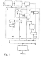
- Fig. 1 is a block diagram of the pulse radar apparatus according to the invention; and
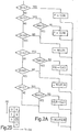
- Figs. 2A, 2B and 3 are diagrams explaining the functions fulfilled by the microprocessor.
- The pulse radar apparatus of Fig. 1 comprises a pulse radar transmitter and
receiver 1, anantenna 2, anFFT processing unit 3, and athreshold circuit 4. The transmitter of the pulse radar apparatus is provided with a magnetron, permitting a coherent detection of first trace echoes, but no coherent detection of multiple trace echoes. In the receiver of the pulse radar apparatus the target returns are, after detection, sampled and digitised per range quant. The digitised video signals thus obtained are passed first through a digital 11TI canceller, forming part of the transmitter andreceiver 1, to eliminate the signals from stationary targets, and then to theFFT processing unit 3. TheFFT processing unit 3 converts the video data, supplied from n successive radar scans and situated in one range bin, into n output signals in the n frequency output channels of the FFT processing unit. If the video data of theradar scans values FFT processing unit 3 supplies. thethreshold circuit 4 with n digital words, namely the amplitudes of n frequency values from the video spectrum. For each of these frequency values, i.e. for each of the frequency output channels of the FFT processing unit, a threshold is established. The frequency values exceeding this threshold are passed. In general the threshold for the centre frequency output channels will be greater than'that for the extreme frequency channels; this is mainly due to the canceller effect in the pulse radar transmitter andreceiver 1. - The signals of amplitudes A. (i = 0, 1, 2, ..., n-1) exceeding the relevant threshold are supplied to a
cell classification unit 5 to derive, from the spectrum range of the target returns processed per radar cell, a cell classification signal (CLASS), whose logical values indicate that the target returns within such a cell are classified in the first instance as first trace and multiple trace signals. Thecell classification unit 5 thereto comprises: acircuit 6 for determining the maximum amplitude AM of frequency output signals A. which output signals exceed the threshold values established for the relevant frequency output channels and which output signals are supplied per radar cell by the FFT processing unit; a preprogrammed memory (PROM) 7; acounter 8; and acomparator 9.Circuit 6 consists of acomparator 10 and aregister 11. The amplitude A. is transferred to register 11 only whencomparator 10 has established that the value of A. is greater than the amplitude already contained inregister 11. A range count pulse RP ensures that for each FFT scan and each .range quant the maximum amplitude inregister 11 is established and retained until the determination of the maximum amplitude for the following range quant from the FFT scan. The maximum amplitude AM is supplied to thePROM 7. In this memory the permissible number of frequency output signals exceeding the threshold values of the relevant frequency output channels at a given maximum amplitude is fixed in order that the target returns may be classified, in the first instance, as first trace echoes. The spectrum of coherently detected first trace echoes will in principle extend over a limited number of frequency output channels, while the spectrum of the multiple trace echoes is arbitrary from FFT scan to FFT scan and extends over a large number of frequency output channels. The number of frequency output channels, where the output signals exceed the corresponding threshold values, are counted incounter 8. If the count ofcounter 8 is equal to or smaller than the value read out ofPROM 7, the target return received in the particular radar cell is classified, in the first instance, as a first trace echo, and thecomparator 9 delivers the cell classification signalCLASS (= 0). If the count ofcounter 8 is greater than the value read out ofPROH 7, the target return is classified, in the first instance, as a multiple trace echo, and thecomparator 9 delivers the CLASS (=1) cell classification signal. Thus the spectrum of the target return in each radar cell provides a preliminary indication of the target return being classificable as a first trace or multiple trace signal. As already set forth in the introductory part of this description, a definite indication thereof is obtained after an averaging process of the preliminary indications over the cells of a cluster. The pulse radar apparatus of Fig. 1 is thereto provided with amicroprocessor 12, comprising: - a. means for combining the cells together covering one single target to form a cluster and for determining a signal representative of the target covered by the cluster;
- b. means for deriving, from the cell classification signals of the cluster cells, a cluster classification signal CLUC, whose logical values indicate that the target returns within the cluster are classified as first trace and multiple trace signals; and
- c. means for reading the signal representative of the target covered by the cluster out of the microprocessor, in so far as the read-out signal is derived from target returns classified as first trace signals.
- In order that the microprocessor be capable of performing the above functions, the following additional signals are required:
- a. signal RG; this signal is indicative of the range of the radar cell from which the video data are processed in the cell classification unit;
- b. signal FN; this signal is indicative of the number of the frequency output channel containing the maximum amplitude.
- In the embodiment in question, the above additional signals are derived in the
cell classification unit 5.Unit 5. comprises achannel counter 13, arange counter 14, and a channel-number register 15. Thechannel counter 13 is triggered with each FFT scan to count the number of frequency output channels of theFFT processing unit 3. After each count therange counter 14 is incremented. Thechannel counter 13 ensures that the number of the maximum amplitude at the instant determined bycomparator 10 is entered in the channel-number register 15. The CLASS, RG and FH signals are supplied tomicroprocessor 12 via themicroprocessor input circuit 16. - The microprocessor combines first the cells together covering one single target to form a cluster and determines a signal representative of the target covered by the cluster. The computing process employed is illustrated in the flow diagram of Fig. 2A. The diagram of Fig. 2B explains the use of the flow diagram. Fig. 2B shows a number of radar cells B, C, D, N, P, Q and R for a number of successive range quants (RG) and FFT scans (FFTSW). In case of adjoining cells of excess amplitude in one or several frequency channels, these cells are combined to form clusters. If in an FFT scan no cells are added to a cluster or if the maximum cluster extent is reached, the cluster is isolated to perform the cluster classification. A cluster may extend over a certain maximum number of FFT scans, for example 7; if, after reaching the maximum width of a cluster, adjoining cells of excess amplitudes are detected, these cells must be added to a new cluster. Therefore, for each cluster the count of the FFT-scan counter must be updated, while the cluster is not to extend beyond a certain maximum number of range quants, for example 4. This is accomplished by counting the number of cells added during an FFT scan and storing this number of the preceding FFT scan. In building up a cluster, the data of the preceding and the current FFT scan is used. Suppose that in cell P in Fig. 2B an excess amplitude has occurred. If cell B belonged to a cluster (B( CL), then cell P is added to this cluster (P→-CL(B)). If cell B did not belong to a cluster (BCL), but cell N did (N ∈ CL), cell P may be added to the cluster of N (P→CL(N)), provided the cluster has not reached its maximum range (MAX.CL). If the cluster has reached the maximum value or if N did not belong to a cluster (N
 CL) and no excess amplitude has been detected (OV(Q)) in cell Q, a new cluster will be produced and will include cell P (→NCL(P)). If however an excess amplitude has occurred in cell Q (OV(Q)) and in cell C as well, cells P and Q are added to the cluster of C (P,Q+ CL(C)), provided the cluster has not reached its maximum range
(MAX.CL). The process shown in the flow diagram continues until either cell P and possibly cell Q,R are added to an existing cluster ( P→CL(B), P→CL(N), P,Q→CL(C) and P,Q,R→CL(D) ), or new clusters are generated, of which P and possibly Q, R form a part (→NCL(P), →NCL(P,Q) and →NCL(P,Q,R) ) . - Amplitudes AM(i) , where i = 1,2,...,k, of k cells belonging to the cluster thus produced are compared in the microprocessor ; the maximum value counts as amplitude for the cluster AM(CL). This signal, which is representative of the target covered by the cluster, can be read out by the microprocessor, in so far as it is derived from target returns classified as first trace signals.
- From the cell classification signals CLASS(i) of the cluster cells the microprocessor determines an average value CLASS from this value the cluster classification signal CLUC is derived. CLASS ave is expressed by:

- If the signal received in cell i is classified as a first trace echo, CLASS(i) = 0; if it is classified as a multiple trace echo, CLASS(i) = 1. In case in the majority of the cells the signal received therein is classified as first trace signal, the return of the target covered by the cluster is considered to be a first trace signal. Conversely, if in the majority of the cells the signals received therein are classified as multiple trace signals, the target return is classified as a multiple trace signal. Thus there are two constant values a and β, where α<β; if CLASS ave <a, this is indicative of first trace echoes (FT); if CLASS >β, this is an indication of multiple trace echoes (MT). If α < CLASSave <β, a further criterion is to distinguish between first trace and multiple trace echoes. To this effect the microprocessor generates a signal NLIJN. If for all cell pairs from the cluster the amplitudes AM(i) are from the same or from two frequency-adjoining output channels of the
FFT processing unit 3, signal NLION=0. If the cluster contains cell pairs, of which the amplitudes AM(i) are from different output channels but not adjoining in frequency, NLION=1. If a <CLASSave < β and NLIUN = 0, the target returns will be classified as FT signals; if however NLIUN = 1, the target returns will be classified as MT signals. The procedure here described is shown in the flow diagram of Fig. 3. - If CLASSave < a, or, in case a < CLASSave <β, NLIUN=0, CLUC = and the microprocessor will read out signal AM(CL) as belonging to a target return classified as first trace signal. In case CLASSave > β, or, in the event a < CLASS <β, NLIUN=1, then CLUC will be 0 and signal AM(CL), as belonging to a target return classified as an MT signal, will be suppressed, i.e. it will not be read out by the microprocessor.
Claims (4)

Applications Claiming Priority (2)
| Application Number | Priority Date | Filing Date | Title |
|---|---|---|---|
| NL8100606A NL8100606A (en) | 1981-02-09 | 1981-02-09 | IMPULSE RADIATOR. |
| NL8100606 | 1981-02-09 |
Publications (2)
| Publication Number | Publication Date |
|---|---|
| EP0057949A1 true EP0057949A1 (en) | 1982-08-18 |
| EP0057949B1 EP0057949B1 (en) | 1985-06-05 |
Family
ID=19836989
Family Applications (1)
| Application Number | Title | Priority Date | Filing Date |
|---|---|---|---|
| EP82200075A Expired EP0057949B1 (en) | 1981-02-09 | 1982-01-22 | Pulse radar apparatus |
Country Status (7)
| Country | Link |
|---|---|
| US (1) | US4524360A (en) |
| EP (1) | EP0057949B1 (en) |
| JP (1) | JPS57148270A (en) |
| AU (1) | AU543907B2 (en) |
| CA (1) | CA1178362A (en) |
| DE (1) | DE3263958D1 (en) |
| NL (1) | NL8100606A (en) |
Cited By (3)
| Publication number | Priority date | Publication date | Assignee | Title |
|---|---|---|---|---|
| FR2566918A1 (en) * | 1984-06-28 | 1986-01-03 | Labo Cent Telecommunicat | System for obtaining summarised information on the line spectrum provided by the spectrum analyser of a Doppler radar |
| EP0187397A1 (en) * | 1984-12-11 | 1986-07-16 | Hollandse Signaalapparaten B.V. | Pulse radar apparatus |
| US8349851B2 (en) | 2009-02-27 | 2013-01-08 | Ambit Biosciences Corp. | JAK kinase modulating compounds and methods of use thereof |
Families Citing this family (3)
| Publication number | Priority date | Publication date | Assignee | Title |
|---|---|---|---|---|
| DE4433776C2 (en) * | 1994-09-22 | 1999-02-18 | Daimler Benz Ag | Pulse radar method |
| NL9401767A (en) * | 1994-10-25 | 1996-06-03 | Hollandse Signaalapparaten Bv | Radar device. |
| US9709433B2 (en) * | 2014-06-30 | 2017-07-18 | Rosemount Tank Radar Ab | Pulsed radar level gauging with efficient start-up |
Citations (5)
| Publication number | Priority date | Publication date | Assignee | Title |
|---|---|---|---|---|
| US3480953A (en) * | 1968-05-17 | 1969-11-25 | Us Army | Moving target indicator having staggered pulse repetition frequency |
| US3610901A (en) * | 1969-09-09 | 1971-10-05 | Emerson Electric Co | Digital modified discrete fourier transform doppler radar processor |
| US3765017A (en) * | 1968-06-12 | 1973-10-09 | North American Rockwell | Amti range ambiguity resolver |
| US3828348A (en) * | 1971-10-21 | 1974-08-06 | Hughes Aircraft Co | System for minimizing multiple time around echos in a coherent-on-receive-doppler radar |
| US4106019A (en) * | 1972-10-05 | 1978-08-08 | Hughes Aircraft Company | Range resolving doppler radar system |
Family Cites Families (5)
| Publication number | Priority date | Publication date | Assignee | Title |
|---|---|---|---|---|
| FR1515000A (en) * | 1966-09-21 | 1968-03-01 | Labo Cent Telecommunicat | Pulsed Coherent Doppler Radar Improvements |
| US3618088A (en) * | 1970-02-26 | 1971-11-02 | Us Federal Aviation Admin | Second-time-around echo immune radar system |
| US4119966A (en) * | 1977-07-14 | 1978-10-10 | Motorola Inc. | Clutter discriminating apparatus for use with pulsed doppler radar systems and the like |
| DE2752338C2 (en) * | 1977-11-23 | 1983-11-17 | Siemens AG, 1000 Berlin und 8000 München | Radar receiver |
| FR2411418A1 (en) * | 1977-12-08 | 1979-07-06 | Labo Cent Telecommunicat | METHOD AND DEVICE FOR ELIMINATING MULTIPLE RETURN ECHOES FOR PULSE DOPPLER RADARS |
-
1981
- 1981-02-09 NL NL8100606A patent/NL8100606A/en not_active Application Discontinuation
-
1982
- 1982-01-22 DE DE8282200075T patent/DE3263958D1/en not_active Expired
- 1982-01-22 EP EP82200075A patent/EP0057949B1/en not_active Expired
- 1982-01-28 CA CA000395136A patent/CA1178362A/en not_active Expired
- 1982-01-29 AU AU79984/82A patent/AU543907B2/en not_active Ceased
- 1982-02-02 US US06/344,917 patent/US4524360A/en not_active Expired - Fee Related
- 1982-02-08 JP JP57017701A patent/JPS57148270A/en active Pending
Patent Citations (5)
| Publication number | Priority date | Publication date | Assignee | Title |
|---|---|---|---|---|
| US3480953A (en) * | 1968-05-17 | 1969-11-25 | Us Army | Moving target indicator having staggered pulse repetition frequency |
| US3765017A (en) * | 1968-06-12 | 1973-10-09 | North American Rockwell | Amti range ambiguity resolver |
| US3610901A (en) * | 1969-09-09 | 1971-10-05 | Emerson Electric Co | Digital modified discrete fourier transform doppler radar processor |
| US3828348A (en) * | 1971-10-21 | 1974-08-06 | Hughes Aircraft Co | System for minimizing multiple time around echos in a coherent-on-receive-doppler radar |
| US4106019A (en) * | 1972-10-05 | 1978-08-08 | Hughes Aircraft Company | Range resolving doppler radar system |
Non-Patent Citations (1)
| Title |
|---|
| IEEE Electro/78 Conference Record Held at Boston MA, 23-25 May 1978 New York (US) Session 28: Paper 28/2 J.D. GRIMM et al.: "Radar Signal Processing Technology" page 1-11 * pages 1-7: Sections Headed Respectively: "Radar Signal Processor Discription", Design Approach (Digital)" * * |
Cited By (3)
| Publication number | Priority date | Publication date | Assignee | Title |
|---|---|---|---|---|
| FR2566918A1 (en) * | 1984-06-28 | 1986-01-03 | Labo Cent Telecommunicat | System for obtaining summarised information on the line spectrum provided by the spectrum analyser of a Doppler radar |
| EP0187397A1 (en) * | 1984-12-11 | 1986-07-16 | Hollandse Signaalapparaten B.V. | Pulse radar apparatus |
| US8349851B2 (en) | 2009-02-27 | 2013-01-08 | Ambit Biosciences Corp. | JAK kinase modulating compounds and methods of use thereof |
Also Published As
| Publication number | Publication date |
|---|---|
| AU7998482A (en) | 1982-08-19 |
| US4524360A (en) | 1985-06-18 |
| EP0057949B1 (en) | 1985-06-05 |
| CA1178362A (en) | 1984-11-20 |
| NL8100606A (en) | 1982-09-01 |
| JPS57148270A (en) | 1982-09-13 |
| DE3263958D1 (en) | 1985-07-11 |
| AU543907B2 (en) | 1985-05-09 |
Similar Documents
| Publication | Publication Date | Title |
|---|---|---|
| US4524358A (en) | Pulse radar apparatus | |
| EP0126032B1 (en) | Device for the identification and suppression of unwanted second trace echoes in radar systems | |
| GB1479665A (en) | Apparatus for reducing clutter in returns produced by a radar system | |
| EP0227457B1 (en) | Radar system | |
| EP0057949B1 (en) | Pulse radar apparatus | |
| US4622556A (en) | Technique for rapid determination of probability of detection in pulse doppler radars | |
| US4274095A (en) | Radar video converter | |
| US4360811A (en) | Adaptive zero mean system for controlling noise false alarm rate | |
| CA1246194A (en) | Pulse radar apparatus | |
| US5748142A (en) | Pulse doppler radar system which identifies and removes electromagnetic interference | |
| EP0054982B1 (en) | Threshold circuit for radar video data | |
| US4503432A (en) | Adaptive threshold detection utilizing a tapped charge transfer device delay line | |
| GB2521097A (en) | Target visibility enhancement system | |
| US4672380A (en) | Gain restoration after doppler filtering | |
| GB2259209A (en) | Radar receivers | |
| Abdullah et al. | Multi-targets detection in a non-homogeneous radar environment using modified CA-CFAR | |
| US5854601A (en) | Methods for estimating the number of emitters and their parameters | |
| US3891987A (en) | One-operation signal processor | |
| GB2074807A (en) | M.T.I. radar processor | |
| Kumar Mardia | Digital signal processing for radar recognition in dense radar environments | |
| JP2576622B2 (en) | Interference signal detection device | |
| US4731612A (en) | Method and apparatus for eliminating short pulses in a doppler radar | |
| GB2212352A (en) | Deinterleaving of radiated signals | |
| CN111308429B (en) | Self-adaptive optimal reference channel selection method and device based on conformal antenna | |
| EP4152042A1 (en) | Method of processing radar signal and radar device |
Legal Events
| Date | Code | Title | Description |
|---|---|---|---|
| PUAI | Public reference made under article 153(3) epc to a published international application that has entered the european phase |
Free format text: ORIGINAL CODE: 0009012 |
|
| AK | Designated contracting states |
Designated state(s): BE CH DE FR GB IT NL SE |
|
| 17P | Request for examination filed |
Effective date: 19821211 |
|
| ITF | It: translation for a ep patent filed |
Owner name: BARZANO' E ZANARDO ROMA S.P.A. |
|
| GRAA | (expected) grant |
Free format text: ORIGINAL CODE: 0009210 |
|
| AK | Designated contracting states |
Designated state(s): BE CH DE FR GB IT LI NL SE |
|
| REF | Corresponds to: |
Ref document number: 3263958 Country of ref document: DE Date of ref document: 19850711 |
|
| ET | Fr: translation filed | ||
| PLBE | No opposition filed within time limit |
Free format text: ORIGINAL CODE: 0009261 |
|
| STAA | Information on the status of an ep patent application or granted ep patent |
Free format text: STATUS: NO OPPOSITION FILED WITHIN TIME LIMIT |
|
| 26N | No opposition filed | ||
| PGFP | Annual fee paid to national office [announced via postgrant information from national office to epo] |
Ref country code: NL Payment date: 19870131 Year of fee payment: 6 |
|
| PG25 | Lapsed in a contracting state [announced via postgrant information from national office to epo] |
Ref country code: GB Effective date: 19890122 |
|
| PG25 | Lapsed in a contracting state [announced via postgrant information from national office to epo] |
Ref country code: SE Effective date: 19890123 |
|
| PG25 | Lapsed in a contracting state [announced via postgrant information from national office to epo] |
Ref country code: LI Effective date: 19890131 Ref country code: CH Effective date: 19890131 Ref country code: BE Effective date: 19890131 |
|
| BERE | Be: lapsed |
Owner name: HOLLANDSE SIGNAALAPPARATEN B.V. Effective date: 19890131 |
|
| PG25 | Lapsed in a contracting state [announced via postgrant information from national office to epo] |
Ref country code: NL Effective date: 19890801 |
|
| NLV4 | Nl: lapsed or anulled due to non-payment of the annual fee | ||
| GBPC | Gb: european patent ceased through non-payment of renewal fee | ||
| PG25 | Lapsed in a contracting state [announced via postgrant information from national office to epo] |
Ref country code: FR Free format text: LAPSE BECAUSE OF NON-PAYMENT OF DUE FEES Effective date: 19890929 |
|
| REG | Reference to a national code |
Ref country code: CH Ref legal event code: PL |
|
| PG25 | Lapsed in a contracting state [announced via postgrant information from national office to epo] |
Ref country code: DE Effective date: 19891003 |
|
| REG | Reference to a national code |
Ref country code: FR Ref legal event code: ST |
|
| EUG | Se: european patent has lapsed |
Ref document number: 82200075.8 Effective date: 19891205 |