EP0057902A2 - Electronic energy controller with automatic warming-up for controlling the heating power of an electrical heating element - Google Patents
Electronic energy controller with automatic warming-up for controlling the heating power of an electrical heating element Download PDFInfo
- Publication number
- EP0057902A2 EP0057902A2 EP82100754A EP82100754A EP0057902A2 EP 0057902 A2 EP0057902 A2 EP 0057902A2 EP 82100754 A EP82100754 A EP 82100754A EP 82100754 A EP82100754 A EP 82100754A EP 0057902 A2 EP0057902 A2 EP 0057902A2
- Authority
- EP
- European Patent Office
- Prior art keywords
- integrated circuit
- energy controller
- switching
- electronic energy
- heating element
- Prior art date
- Legal status (The legal status is an assumption and is not a legal conclusion. Google has not performed a legal analysis and makes no representation as to the accuracy of the status listed.)
- Withdrawn
Links
Images
Classifications
-
- H—ELECTRICITY
- H05—ELECTRIC TECHNIQUES NOT OTHERWISE PROVIDED FOR
- H05B—ELECTRIC HEATING; ELECTRIC LIGHT SOURCES NOT OTHERWISE PROVIDED FOR; CIRCUIT ARRANGEMENTS FOR ELECTRIC LIGHT SOURCES, IN GENERAL
- H05B1/00—Details of electric heating devices
- H05B1/02—Automatic switching arrangements specially adapted to apparatus ; Control of heating devices
- H05B1/0227—Applications
- H05B1/0252—Domestic applications
- H05B1/0258—For cooking
- H05B1/0261—For cooking of food
- H05B1/0266—Cooktops
-
- F—MECHANICAL ENGINEERING; LIGHTING; HEATING; WEAPONS; BLASTING
- F24—HEATING; RANGES; VENTILATING
- F24C—DOMESTIC STOVES OR RANGES ; DETAILS OF DOMESTIC STOVES OR RANGES, OF GENERAL APPLICATION
- F24C7/00—Stoves or ranges heated by electric energy
- F24C7/08—Arrangement or mounting of control or safety devices
- F24C7/087—Arrangement or mounting of control or safety devices of electric circuits regulating heat
-
- G—PHYSICS
- G05—CONTROLLING; REGULATING
- G05D—SYSTEMS FOR CONTROLLING OR REGULATING NON-ELECTRIC VARIABLES
- G05D23/00—Control of temperature
- G05D23/19—Control of temperature characterised by the use of electric means
- G05D23/1906—Control of temperature characterised by the use of electric means using an analogue comparing device
- G05D23/1913—Control of temperature characterised by the use of electric means using an analogue comparing device delivering a series of pulses
Definitions
- the invention relates to an electronic energy controller with automatic heating for controlling the heating power of an electrical heating element, e.g. a cooking device which consists of an electronic multivibrator circuit switching a load switching element, the pulse duty factor of which can be adjusted manually by means of a potentiometer coupled to a mains switch.
- an electrical heating element e.g. a cooking device which consists of an electronic multivibrator circuit switching a load switching element, the pulse duty factor of which can be adjusted manually by means of a potentiometer coupled to a mains switch.
- a device of this kind is e.g. made known by an electronic power controller according to DE-AS 25 49 535.
- This consists of an operational amplifier circuit that is constructed with analog and linear components.
- the object of the invention is to improve and design an electronic energy controller in such a way that it can be manufactured in a small space with simple components in such a way that energy savings in the operation of hotplates can be achieved by detecting residual heat without a special sensor Cooking area is enabled, which is automatically used by the energy controller for another cooking process without risk of overheating the cooking area. At the same time, an indication of the residual heat of the hotplate is achieved, by means of which the user is shown the risk of possible burns on hot hotplates.
- the multivibrator circuit consists of a digital integrated circuit which is constantly supplied with voltage for its direct current supply via a power supply unit, depending on the operating status of that Mains switch can be supplied via a resistor and is provided with a synchronization input for the synchronization and clocking of the switching processes, to which the mains frequency can be supplied via a resistor and that a thyristor for switching a signal lamp is dependent on the activation of the heating element and / or at least one other Switchable heating element that the signal lamp lights up briefly after switching on and goes out long after switching off.
- a so-called hot display in which it is possible to display the residual heat of a hotplate for safety reasons and to save energy, without the need for further switching elements.
- the hot signal is switched by the integrated circuit in times adapted to the respective purpose. For example, When used with electric cookers, the signal lights up 7 seconds after the hob is switched on and 30 minutes after the hob is switched off.
- a resistance combination is connected to the thyristor for actuation.
- a 220 V signal can be fed to the integrated circuit for influencing the thyristors T1 via a further power supply unit as a low-voltage direct voltage.
- the integrated circuit can be switched to zero potential with an input via a clock with a low-current or semiconductor switch.
- a time switch can be used for this purpose, which only has a low-current switch or a semiconductor switch. The switching of the load current is carried out by the load circuit of the electronic energy controller. A time switch with a complex contact system is therefore not necessary.
- a further embodiment of the invention consists in that the potentiometer is connected with its one resistance end to the supply voltage input of the integrated circuit and is connected with its other resistance end to another input of the integrated circuit, whereby a signal can be supplied to the integrated circuit in the event of a fault in the control circuit. that puts the thyristor in a running on-off state and the duty cycle controlling the load switching element in the minimum.
- a capacitor and / or resistor which shifts the time of the switching of the load switching element into the region of the voltage zero crossing is provided.
- an automatic, assigned heating-up period can be switched digitally, taking into account a residual heat of the heating element, depending on the duty cycle set by the potentiometer.
- the heating period can be switched off by the integrated circuit depending on the setting of the potentiometer in the direction of lower heating power and can be switched on again in the direction of higher heating power.
- the electronic energy controller is shown in the drawing using an exemplary embodiment.
- the neutral conductor of the network is at terminal N 1.
- integrated circuit 1 receives the network frequency at a connection 1.6 of a synchronization input for synchronizing and clocking the time sequences.
- the integrated circuit 1 is thus constantly energized, so that it is constantly on standby for its function of the switching operations described below, which it enables.
- the integrated circuit 1 detects the operating state ON or OFF via the power switch 2, which connects the terminal P 1.1 of the heating element to the phase P 1 of the network and applies the resistor R 1 to voltage.
- the desired heating output is set via the center tap of a potentiometer R 3, which is coupled to the power switch 2 in a rotationally locking manner.
- the potentiometer R 3 is connected to the power supply of the integrated circuit 1 at the terminal 1.16.
- a thyristor T 2 is driven via the resistor R 9, which excites the coil circuit of a relay 5 which acts as a load switching element.
- the excitation energy of relay 5 is limited by resistor R 10, rectified by thyristor T 2 and smoothed by capacitor C 2.
- the heating element 3 is connected with its terminal N 2 to the neutral conductor of the network, and a signal circuit can also be switched via the terminals P 2 and P 2.1 of the mains switch 2.
- a hot indicator is connected to the integrated circuit 1 via the resistors R 6 and R 7 and the thyristor T 1, whereby a signal lamp located between the terminal H 1 and the phase of the network is controlled.
- the resistors R 6 and R 7 serve as control resistors, namely R 6 in the case of the 0 state and R 7 in the case of the L state at the output 1.11 of the integrated circuit 1.
- the integrated circuit 1 can be connected to zero potential at its input 1.5 via a time switch 4, as a result of which the power controller function is blocked. This makes it possible to carry out fully automatic, time-dependent cooking processes which run automatically at a given time after the mains switch 2 has been switched on and the time switch 4 has been set. Since the switching of the load current is also taken over by the load switching element 5 of the circuit, only a low-voltage or semiconductor switch is required in the time switch 4. The output power of a digital clock IC is also sufficient for time-dependent signaling.
- potentiometer R 3 While the potentiometer R 3 has one resistance end connected to the supply voltage input 1.16 of the integrated circuit 1, its other resistance end is connected to another input 1.3 of the integrated circuit 1. If the control circuit of the circuit malfunctions, e.g. Interruption, signals are thus supplied to the integrated circuit 1, as a result of which the thyristor T 1 is set in a running on-off state, so that the signal lamp of the so-called hot display is switched to a flashing mode. With this signal, the output power of the circuit is simultaneously reduced to the minimum, e.g. 3% down. In this way, faults that occur are easily recognized and adverse effects on the cooking device are avoided.
- the control circuit of the circuit malfunctions, e.g. Interruption, signals are thus supplied to the integrated circuit 1, as a result of which the thyristor T 1 is set in a running on-off state, so that the signal lamp of the so-called hot display is switched to a flashing mode. With this signal, the output power of the
- the integrated circuit 1 depending on the duty cycle, which can be set manually by means of the potentiometer R 3, can be used to digitally switch an automatic heating period associated with the respectively set duty cycle.
- the residual heat present in the heating element 3 is automatically taken into account if this was previously switched on for a cooking process.
- the integrated circuit 1 is designed so that its output signal has a clock cycle of 30 seconds. This corresponds to an optimal time ratio for switching on cooktops heated with radiant heaters, eg glass ceramic cooktops. In the case of radiators with low inertia, this makes it possible to switch constant temperatures in the power levels set in each case and the service life of the power switching element 5 which switches the power adapted a cooker life provided.
- the integrated circuit is designed in such a way that a minimum heating-up period of 1 minute is maintained in every switch-on position of the energy controller. During this time, only a change in the duty cycle is possible. This changed setting only takes effect after this time has elapsed, in that the heating period and continued cooking power assigned to the changed duty cycle are then set. After the minimum heating period of 1 min has elapsed, the heating period set can be switched off by adjusting the potentiometer R 3 in the direction of lower heating power and switched on again in the direction of higher heating power.
- the integrated circuit 1 is designed so that it has a temperature resistance up to max. 125 0 . Furthermore, it is characterized by its special design for its extremely versatile control processes due to its minimal size.
Abstract
Description
Die Erfindung betrifft einen elektrcnischen Energiesteller mit Anheizautomatik zur Steuerung der Heizleistung eines elektrischen Heizelementes, z.B. einer Kocheinrichtung, der aus einer ein Lastschaltglied schaltenden elektronischen Multivibratorschaltung besteht, deren Tastverhältnis manuell durch ein mit einem Netzschalter gekuppelten Potentiometer einstellbar ist.The invention relates to an electronic energy controller with automatic heating for controlling the heating power of an electrical heating element, e.g. a cooking device which consists of an electronic multivibrator circuit switching a load switching element, the pulse duty factor of which can be adjusted manually by means of a potentiometer coupled to a mains switch.
Eine Einrichtung dieser Art ist z.B. durch einen elektronischen Leistungssteller nach DE-AS 25 49 535 bekannt geworden. Diese besteht aus einer Operations-Verstärker-Schaltung, die mit analogen und linearen Bauelementen aufgebaut ist.A device of this kind is e.g. made known by an electronic power controller according to DE-AS 25 49 535. This consists of an operational amplifier circuit that is constructed with analog and linear components.
Aufgabe der Erfindung ist es, einen elektronischen Energiesteller derart zu verbessern und auszubilden, daß er auf kleinstem Raum mit einfachen Bauteilen so herstellbar.ist, daß durch ihn eine Energieeinsparung bei der Betreibung von Kochstellen erzielbar ist, indem ohne besondere Fühler eine Erfassung von Restwärme einer Kochstelle ermöglicht ist, die durch den Energiesteller automatisch für einen weiteren Kochvorgang ohne Gefahr der Überhitzung der Kochstelle verwertet wird. Gleichzeitig wird dabei eine Anzeige der Restwärme der Kochstelle erzielt, durch die dem Benutzer die Gefahr einer möglichen Verbrennung an noch heißen Kochstellen angezeigt wird.The object of the invention is to improve and design an electronic energy controller in such a way that it can be manufactured in a small space with simple components in such a way that energy savings in the operation of hotplates can be achieved by detecting residual heat without a special sensor Cooking area is enabled, which is automatically used by the energy controller for another cooking process without risk of overheating the cooking area. At the same time, an indication of the residual heat of the hotplate is achieved, by means of which the user is shown the risk of possible burns on hot hotplates.
Erfindungsgemäß wird dies dadurch gelöst, daß die Multivibratorschaltung aus einem digitalen integrierten Schaltkreis besteht, der zu seiner Gleichstromversorgung über ein Netzteil ständig an Spannung liegt, dem der Betriebsstand von dem Netzschalter über einen Widerstand zuführbar ist und der für die Synchronisation und Taktung der Schaltvorgänge mit einem Synchronisationseingang versehen ist, dem die Netzfrequenz über einen Widerstand zuführbar ist und daß ein Thyristor zur Schaltung einer Signallampe derart abhängig von der Einschaltung des Heizelementes und/oder mindestens eines weiteren Heizelementes schaltbar ist, daß die Signallampe kurzfristig nach Einschaltung aufleuchtet und langfristig nach Abschaltung erlischt.According to the invention, this is achieved in that the multivibrator circuit consists of a digital integrated circuit which is constantly supplied with voltage for its direct current supply via a power supply unit, depending on the operating status of that Mains switch can be supplied via a resistor and is provided with a synchronization input for the synchronization and clocking of the switching processes, to which the mains frequency can be supplied via a resistor and that a thyristor for switching a signal lamp is dependent on the activation of the heating element and / or at least one other Switchable heating element that the signal lamp lights up briefly after switching on and goes out long after switching off.
Es wird hierdurch ein elektronischer Energiesteller geschaffen, daß nur einen kleinen Bauraum benötigt und mit dem ohne Verwendung eines besonderen Temperaturfühlers eine Leistungsschaltung mit Anheizperiode und reduzierter Fortkochleistung einer elektrischen Kochstelle zuverlässig in den eingestellten gewünschten Kochbereichen möglich ist. Gleichzeitig erfolgt dabei eine sogenannte HeiBanzeige, bei der es möglich ist, aus Sicherheitsgründen und zur Energieeinsparung die Restwärme einer Kochstelle anzuzeigen, ohne daß hierzu weitere Schaltelemente erforderlich werden. Das Heißsignal wird durch den integrierten Schaltkreis in dem jeweiligen Verwendungszweck angepassten Zeiten geschaltet. So kann z.B. in der Verwendung bei Elektroherden das Signal 7 Sek. nach Einschaltung der Kochstelle aufleuchten und 30 Min. nach Abschaltung der Kochstelle abschalten.This creates an electronic energy controller that only requires a small installation space and with which a power circuit with heating period and reduced continued cooking power of an electric hotplate is reliably possible in the set desired cooking areas without the use of a special temperature sensor. At the same time there is a so-called hot display, in which it is possible to display the residual heat of a hotplate for safety reasons and to save energy, without the need for further switching elements. The hot signal is switched by the integrated circuit in times adapted to the respective purpose. For example, When used with electric cookers, the signal lights up 7 seconds after the hob is switched on and 30 minutes after the hob is switched off.
Nach weiterer Ausgestaltung ist dem Thyristor zur Ansteuerung eine Widerstandskombination zugeschaltet.According to a further embodiment, a resistance combination is connected to the thyristor for actuation.
Nach weiterer Erfindung ist über einen externen Anschluss ein 220 V-Signal über ein weiteres Netzteil als Niedervolt-Gleichspannung dem integrierten Schaltkreis zur Beeinflussung der Thyristors T1 zuführbar.According to a further invention, a 220 V signal can be fed to the integrated circuit for influencing the thyristors T1 via a further power supply unit as a low-voltage direct voltage.
Hierdurch besteht die Möglichkeit, daß weitere parallel geschaltete Schaltersysteme ohne besondere Heiß-Anzeigevorrichtungen durch den elektronischen Energiesteller ebenfalls erfaßt werden können.As a result, there is the possibility that further switch systems connected in parallel can also be detected by the electronic energy controller without special hot display devices.
Nach weiterer Ausgestaltung ist der integrierte Schaltkreis mit einem Eingang über eine Uhr mit Schwachstrom- oder Halbleiterschalter gegen Null-Potential schaltbar.According to a further embodiment, the integrated circuit can be switched to zero potential with an input via a clock with a low-current or semiconductor switch.
Hierdurch wird bei Einschaltung des Netzschalters des elektronischen Energiestellers die Leistungssteller-Funktion blockiert, die je nach Einstellung der Schaltuhr für die Ausführung eines Kochvorganges freigegeben werden kann. Zu diesem Zweck kann eine Schaltuhr verwendet werden, die lediglich einen Schwachstrom- oder einen Halbleiterschalter aufweist. Die Schaltung des Laststromes wird vom Lastschaltkreis des elektronischen Energiestellers übernommen. Eine Schaltuhr mit aufwendigem Kontaktsystem ist somit nicht erforderlich.As a result, when the mains switch of the electronic energy controller is switched on, the power controller function is blocked, which, depending on the setting of the time switch, can be released for the execution of a cooking process. A time switch can be used for this purpose, which only has a low-current switch or a semiconductor switch. The switching of the load current is carried out by the load circuit of the electronic energy controller. A time switch with a complex contact system is therefore not necessary.
Eine weitere Ausbildung der Erfindung besteht darin, daß das Potentiometer mit seinem einen Widerstandsende an dem Versorgungsspannungseingang des integrierten Schaltkreises liegt und mit seinem anderen Widerstandsende mit einem anderen Eingang des integrierten Schaltkreises verbunden ist, wodurch bei Störung des Ansteuerkreises dem integrierten Schaltkreis ein Signal zuführbar ist, das den Thyristor in einen laufenden Ein- Auszustand und das das Lastschaltglied steuernde Tastverhältnis in das Minimum versetzt.A further embodiment of the invention consists in that the potentiometer is connected with its one resistance end to the supply voltage input of the integrated circuit and is connected with its other resistance end to another input of the integrated circuit, whereby a signal can be supplied to the integrated circuit in the event of a fault in the control circuit. that puts the thyristor in a running on-off state and the duty cycle controlling the load switching element in the minimum.
Bei Störung des Ansteuerkreises wird hierdurch ein Signal dem integrierten Schaltkreis zugeführt, so daß die Ausgangsleistung der Schaltung heruntergeschaltet wird, z.B. auf ca. 3 %. Gleichzeitig erfolgt hierdurch ein Blinkbetrieb der Signallampe der sogenannten Heißanzeige, wodurch der Störfall erkennbar wird.In the event of a fault in the control circuit, a signal is hereby fed to the integrated circuit, so that the output power of the circuit is reduced, for example to approximately 3%. At the same time, this causes the flashing mode Signal lamp of the so-called hot display, which makes the fault recognizable.
Nach weiterer Ausgestaltung ist zwischen dem Versorgungsspannungseingang und einem weiteren Eingang des integriertem Schaltkreises ein den Zeitpunkt der Schaltung des Lastschaltgliedes in den Bereich des Spannungs-Null-Durchgangs verlegender Kondensator und/oder Widerstand vorgesehen.According to a further embodiment, between the supply voltage input and a further input of the integrated circuit, a capacitor and / or resistor which shifts the time of the switching of the load switching element into the region of the voltage zero crossing is provided.
Es werden hierdurch eine größere Kontaktlebensdauer und eine verringerte Funkstörung im Stromnetz erzielt.This results in a longer contact life and reduced radio interference in the power network.
Nach weiterer Erfindung ist durch den integrierten Schaltkreis in Abhängigkeit vom durch das Potentiometer eingestellten Tastverhältnis eine automatische, zugeordnete Anheizperiode unter Berücksichtigung einer Restwärme des Heizelementes digital schaltbar.According to a further invention, an automatic, assigned heating-up period can be switched digitally, taking into account a residual heat of the heating element, depending on the duty cycle set by the potentiometer.
Schließlich ist die Anheizperiode durch den integrierten Schaltkreis in Abhängigkeit der Einstellung des Potentiometers in Richtung geringerer Heizleistung ausschaltbar und in Richtung höherer Heizleistung wiedereinschaltbar.Finally, the heating period can be switched off by the integrated circuit depending on the setting of the potentiometer in the direction of lower heating power and can be switched on again in the direction of higher heating power.
Der elektronische Energiesteller ist in der Zeichnung an einem Ausführungsbeispiel dargestellt.The electronic energy controller is shown in the drawing using an exemplary embodiment.
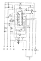
Der integrierte Schaltkreis 1, der für die Leistungssteuerung eines elektrischen Heizelementes 3 lediglich mit 16 Außenanschlüssen 1.1 bis 1.16 versehen ist, bildet das Herzstück der Schaltung und erfüllt dabei mit seiner Peripherie-Beschaltung folgende Funktionen:
- Die Diode D2 ist an der Phase des Netzes mit der Klemme P 1 angeschlossen und bildet in Verbindung mit dem Widerstand R 4 und dem Kondensator C 1 die Stromversorgung des integrierten Schaltkreises 1 aus einem 220 V-Wechselstromnetz.
- The diode D2 is connected to the phase of the network with the terminal P 1 and, in conjunction with the resistor R 4 and the capacitor C 1, forms the power supply for the integrated circuit 1 from a 220 V AC network.
Der Null-Leiter des Netzes liegt an der Klemme N 1. Über den Widerstand R 2 erhält der integrierte Schaltkreis 1 an einem Anschluß 1.6 eines Synchronisationseingangs die Netzfrequenz zur Synchronisation und Taktung der Zeitabläufe. Der integrierte Schaltkreis 1 ist somit ständig an Spannung gelegt, so daß er für seine Funktion der weiter unten beschriebenen, durch ihn möglichen Schaltvorgänge ständig in Bereitschaft ist. Über den Netzschalter 2, der die Klemme P 1.1 des Heizelementes mit der Phase P 1 des Netzes verbindet, und den Widerstand R 1 an Spannung legt, erkennt der integrierte Schaltkreis 1 den Betriebszustand EIN oder AUS. Die Einstellung der gewünschten Heizleistung geschieht über den Mittelabgriff eines Potentiometers R 3, das mit dem Netzschalter 2 drehungsschlüssig gekuppelt ist. Das Potentiometer R 3 ist an der Stromversorgung des integrierten Schaltkreises 1 an der Klemme 1.16 angeschlossen. Vom Ausgang 1.10 des integrierten Schaltkreises 1 wird über den Widerstand R 9 ein Thyristor T 2 angesteuert, der den Spulenstromkreis eines als Lastschaltglied wirksamen Relais 5 erregt. Die Erreger-Energie des Relais 5 wird über den Widerstand R 10 begrenzt, durch den Thyristor T 2 gleichgerichtet und durch den Kondensator C 2 geglättet. Durch den Relaiskontakt wird das Heizelement 3 mit seiner Klemme N 2 mit dem Null-Leiter des Netzes verbunden, über die Klemmen P 2 und P 2.1 des Netzschalters 2 kann noch ein Signalkreis geschaltet werden.The neutral conductor of the network is at terminal N 1. Via
An dem integrierten Schaltkreis 1 ist über die Widerstände R 6 und R 7 sowie den Thyristor T 1 eine Heißanzeige angeschlossen, wodurch eine zwischen der Klemme H 1 und der Phase des Netzes liegende Signallampe gesteuert wird. Dabei dienen die Widerstände R 6 und R 7 als Ansteuerungswiderstände, und zwar R 6 im Fall des 0-Zustandes und R 7 im Fall des L-Zustandes am Ausgang 1.11 des integrierten Schaltkreises 1.A hot indicator is connected to the integrated circuit 1 via the resistors R 6 and R 7 and the thyristor T 1, whereby a signal lamp located between the terminal H 1 and the phase of the network is controlled. The resistors R 6 and R 7 serve as control resistors, namely R 6 in the case of the 0 state and R 7 in the case of the L state at the output 1.11 of the integrated circuit 1.
Darüber hinaus besteht die Möglichkeit, weitere parallel geschaltete Schaltersysteme, die mechanische Schalter sein können und durch die weitere Kochstellen der Kocheinrichtung schaltbar sind, an die vorhandene Heißanzeige des elektronischen Energiestellers anzuschließen. Ein von diesen weiteren Schaltersystemen an der Anschlußklemme H 2 ankommende? 220 V-Signal wird über die Diode D 1 und den Widerstand R 8 dem Eingang 1.4 des integrierten Schaltkreises 1 zugeführt. Zu diesem Schaltzweig gehören noch die Spannungsbegrenzungsdiode D 3 und D 4 und der zur Glättung dienende Kondensator C 3. Die durch diesen Schaltzweig dem integrierten Schaltkreis 1 zugeführten Signale der weiteren Schaltersysteme werden ebenfalls über den integrierten Schaltkreis 1 auf den Thyristor T 1 geleitet zur Schaltung der an der Klemme H 1 angeschlossenen Signallampe. Es ist hierdurch eine gemeinsame Sicherheitsanzeige aller Kochstellen ermöglicht. Gleichzeitig wird durch dieses Heißsignal angezeigt, daß in einer Kochstelle noch Restwärme vorhanden ist, die weiter nutzbar gemacht werden kann.In addition, there is the possibility of connecting further switch systems connected in parallel, which can be mechanical switches and can be switched by the further hotplates of the cooking device, to the existing hot display of the electronic energy controller. One of these other switch systems arriving at
Der integrierte Schaltkreis 1 kann an seinem Eingang 1.5 über eine Schaltuhr 4 gegen Null-Potential geschaltet sein, wodurch die Leistungssteller-Funktion blockiert wird. Hierdurch ist es möglich, vollautomatische, uhrzeitabhängige Kochvorgänge durchzuführen, die nach Einschaltung des Netzschalters 2 und Einstellung der Schaltuhr 4 zum gegebenen Zeitpunkt selbstätig ablaufen. Da die Schaltung des Laststromes hierbei ebenfalls von dem Lastschaltglied 5 der Schaltung übernommen wird, wird in der Schaltuhr 4 lediglich ein Schwachstrom- oder Halbleiterschalter benötigt. Zur zeitabhängigen Signalgabe reicht auch die Ausgangsleistung eines Digitaluhr-IC's aus.The integrated circuit 1 can be connected to zero potential at its input 1.5 via a time switch 4, as a result of which the power controller function is blocked. This makes it possible to carry out fully automatic, time-dependent cooking processes which run automatically at a given time after the
Während das Potentiometer R 3 mit seinem einen Widerstandsende an dem Versorgungsspannungseingang 1.16 des integrierten Schaltkreises 1 liegt, ist sein anderes Widerstandsende mit einem anderen Eingang 1.3 des integrierten Schaltkreises 1 verbunden. Bei Störung des Ansteuerkreises der Schaltung, z.B. Unterbrechung, werden somit Signale dem integrierten Schaltkreis 1 zugeführt, wodurch der Thyristor T 1 in einen laufenden Ein- Auszustand versetzt wird, so daß die Signallampe der sogenannten Heißanzeige in einen Blinkbetrieb überführt wird. Es wird durch dieses Signal gleichzeitig die Ausgangsleistung der Schaltung unmittelbar auf das Minimum, z.B. 3 % heruntergeschaltet. Es werden hierdurch auftretende Störungen leicht erkennbar und nachteilige Auswirkungen auf die Kocheinrichtung vermieden.While the potentiometer R 3 has one resistance end connected to the supply voltage input 1.16 of the integrated circuit 1, its other resistance end is connected to another input 1.3 of the integrated circuit 1. If the control circuit of the circuit malfunctions, e.g. Interruption, signals are thus supplied to the integrated circuit 1, as a result of which the thyristor T 1 is set in a running on-off state, so that the signal lamp of the so-called hot display is switched to a flashing mode. With this signal, the output power of the circuit is simultaneously reduced to the minimum, e.g. 3% down. In this way, faults that occur are easily recognized and adverse effects on the cooking device are avoided.
Durch die Beschaltung des Eingangs 1.9 des integrierten Schaltkreises 1 über den Widerstand R 5 wird der Zeitpunkt des Schaltvorganges des Lastschaltgliedes 5 in den Bereich des Phasen-Null-Durchgangs verlegt.By wiring the input 1.9 of the integrated circuit 1 via the
Durch den integrierten Schaltkreis 1 wird in Abhängigkeit von dem Tastverhältnis, das durch das Potentiometer R 3 manuell einstellbar ist, eine automatische, dem jeweiligen eingestellten Tastverhältnis zugeordnete Anheizperiode digital schaltbar. Dabei erfolgt automatisch eine Berücksichtigung der in dem Heizelement 3 vorhandenen Restwärme, wenn dieses zuvor bereits für einen Kochvorgang eingeschaltet war. Der integrierte Schaltkreis 1 ist so ausgelegt, daß sein Ausgangssignal einen Zeittakt von 30 Sek. aufweist. Dies entspricht einem optimalen Zeitverhältnis zur Schaltung von mit Strahlungsheizkörpern beheizten Kochfeldern, z.B. Glaskeramikkochfelder. Es werden hierdurch bei Heizkörpern mit geringer Trägheit konstante Temperaturen in den jeweils eingestellten Leistungsstufen schaltbar und die Lebensdauer des die Leistung schaltenden Lastschaltgliedes 5 der für einen Kochherd vorgesehenen Lebensdauer angepaßt.The integrated circuit 1, depending on the duty cycle, which can be set manually by means of the potentiometer R 3, can be used to digitally switch an automatic heating period associated with the respectively set duty cycle. The residual heat present in the heating element 3 is automatically taken into account if this was previously switched on for a cooking process. The integrated circuit 1 is designed so that its output signal has a clock cycle of 30 seconds. This corresponds to an optimal time ratio for switching on cooktops heated with radiant heaters, eg glass ceramic cooktops. In the case of radiators with low inertia, this makes it possible to switch constant temperatures in the power levels set in each case and the service life of the
Weiterhin ist der integrierte Schaltkreis so ausgelegt, daß in jeder Einschaltstellung des Energiestellers eine Mindest-Anheizperiode von 1 Min. eingehalten wird. Während dieser Zeit ist nur eine Änderung des Tastverhältnisses möglich. Erst nach Ablauf dieser Zeit wirkt sich diese veränderte Einstellung aus, indem sich dann die dem geänderten Tastverhältnis zugeordnete Anheizperiode und Fortkochleistung einstellt. Nacl Ablauf der Mindest-Anheizperiode von 1 Min. kann die eingestellte Anheizperiode durch Verstellen des Potentiometers R 3 in Richtung geringere Heizleistung ausgeschaltet und in Richtung höherer Heizleistung wieder eingeschaltet werden. Dazu reicht jeweils eine Verstellung des Einstellgliedes um einen Skalenteil, z.B. bei einer 12er Teilung.Furthermore, the integrated circuit is designed in such a way that a minimum heating-up period of 1 minute is maintained in every switch-on position of the energy controller. During this time, only a change in the duty cycle is possible. This changed setting only takes effect after this time has elapsed, in that the heating period and continued cooking power assigned to the changed duty cycle are then set. After the minimum heating period of 1 min has elapsed, the heating period set can be switched off by adjusting the potentiometer R 3 in the direction of lower heating power and switched on again in the direction of higher heating power. One adjustment of the setting element by one scale, e.g. with a division of 12.
Der integrierte Schaltkreis 1 ist so ausgeführt, daß er eine Temperaturbeständigkeit bis max. 125 0 aufweist. Weiterhin zeichnet er sich durch seine spezielle Auslegung für seine äußerst vielseitigen Steuervorgänge durch eine minimale Baugröße aus.The integrated circuit 1 is designed so that it has a temperature resistance up to max. 125 0 . Furthermore, it is characterized by its special design for its extremely versatile control processes due to its minimal size.
Claims (8)
Applications Claiming Priority (2)
| Application Number | Priority Date | Filing Date | Title |
|---|---|---|---|
| DE3104837 | 1981-02-11 | ||
| DE19813104837 DE3104837A1 (en) | 1981-02-11 | 1981-02-11 | ELECTRONIC ENERGY CONTROLLER WITH HEATING AUTOMATION FOR CONTROLLING THE HEATING OUTPUT OF AN ELECTRICAL HEATING ELEMENT |
Publications (2)
| Publication Number | Publication Date |
|---|---|
| EP0057902A2 true EP0057902A2 (en) | 1982-08-18 |
| EP0057902A3 EP0057902A3 (en) | 1984-02-22 |
Family
ID=6124570
Family Applications (1)
| Application Number | Title | Priority Date | Filing Date |
|---|---|---|---|
| EP82100754A Withdrawn EP0057902A3 (en) | 1981-02-11 | 1982-02-03 | Electronic energy controller with automatic warming-up for controlling the heating power of an electrical heating element |
Country Status (2)
| Country | Link |
|---|---|
| EP (1) | EP0057902A3 (en) |
| DE (1) | DE3104837A1 (en) |
Cited By (2)
| Publication number | Priority date | Publication date | Assignee | Title |
|---|---|---|---|---|
| AT390536B (en) * | 1986-02-11 | 1990-05-25 | Acotronic Elektronische Appara | Circuit for traffic measurement in automatic exchanges of telephone traffic |
| FR2739176A1 (en) * | 1995-09-27 | 1997-03-28 | Seb Sa | Electrical heater for heating contents of baby's feeding bottle |
Families Citing this family (5)
| Publication number | Priority date | Publication date | Assignee | Title |
|---|---|---|---|---|
| DE3240547A1 (en) * | 1982-11-03 | 1984-06-14 | Diehl Gmbh & Co | CIRCUIT ARRANGEMENT FOR SWITCHING THE POWER SUPPLY TO ELECTRICAL CONSUMERS |
| DE8817041U1 (en) * | 1988-07-22 | 1992-02-20 | Bosch-Siemens Hausgeraete Gmbh, 8000 Muenchen, De | |
| DE4038167B4 (en) * | 1989-12-15 | 2005-10-20 | Bernhard Rall | Arrangement for heating flexible mats, textiles or the like |
| DE4029181A1 (en) * | 1990-09-14 | 1992-03-19 | Miele & Cie | Baking oven with different types of heating - switches on e.g. upper, lower, heating elements, grill and convection heater during initial heat-up phase |
| DE19941299A1 (en) * | 1999-08-31 | 2001-03-01 | Eckhard Wahl | Controller for electric cooker plate heat regulation has electronic time switch combined with heat sensor, each plate having only two connections, electronic time switch element controls heat |
Citations (7)
| Publication number | Priority date | Publication date | Assignee | Title |
|---|---|---|---|---|
| CH529379A (en) * | 1969-10-27 | 1972-10-15 | Telemecanique Electrique | Electrical device for regulating the temperature at a plurality of points |
| DE2437867A1 (en) * | 1973-08-09 | 1975-02-20 | Rca Corp | POWER CONTROL DEVICE |
| US3982098A (en) * | 1974-12-23 | 1976-09-21 | Trostler Richard M | Heater and control system |
| FR2385135A1 (en) * | 1977-03-25 | 1978-10-20 | Radiotechnique Compelec | DAILY PROGRAMMER, ESPECIALLY FOR ENERGY SAVING BY HEATING MODULATION |
| DE2915797A1 (en) * | 1978-04-20 | 1979-10-25 | Matsushita Electric Ind Co Ltd | TEMPERATURE CONTROL SYSTEM |
| DE2549535B2 (en) * | 1975-11-05 | 1980-05-29 | Brown, Boveri & Cie Ag, 6800 Mannheim | Electronic power divider |
| US4222037A (en) * | 1978-12-05 | 1980-09-09 | General Electric Company | Cooking cycle timer |
-
1981
- 1981-02-11 DE DE19813104837 patent/DE3104837A1/en not_active Withdrawn
-
1982
- 1982-02-03 EP EP82100754A patent/EP0057902A3/en not_active Withdrawn
Patent Citations (7)
| Publication number | Priority date | Publication date | Assignee | Title |
|---|---|---|---|---|
| CH529379A (en) * | 1969-10-27 | 1972-10-15 | Telemecanique Electrique | Electrical device for regulating the temperature at a plurality of points |
| DE2437867A1 (en) * | 1973-08-09 | 1975-02-20 | Rca Corp | POWER CONTROL DEVICE |
| US3982098A (en) * | 1974-12-23 | 1976-09-21 | Trostler Richard M | Heater and control system |
| DE2549535B2 (en) * | 1975-11-05 | 1980-05-29 | Brown, Boveri & Cie Ag, 6800 Mannheim | Electronic power divider |
| FR2385135A1 (en) * | 1977-03-25 | 1978-10-20 | Radiotechnique Compelec | DAILY PROGRAMMER, ESPECIALLY FOR ENERGY SAVING BY HEATING MODULATION |
| DE2915797A1 (en) * | 1978-04-20 | 1979-10-25 | Matsushita Electric Ind Co Ltd | TEMPERATURE CONTROL SYSTEM |
| US4222037A (en) * | 1978-12-05 | 1980-09-09 | General Electric Company | Cooking cycle timer |
Cited By (2)
| Publication number | Priority date | Publication date | Assignee | Title |
|---|---|---|---|---|
| AT390536B (en) * | 1986-02-11 | 1990-05-25 | Acotronic Elektronische Appara | Circuit for traffic measurement in automatic exchanges of telephone traffic |
| FR2739176A1 (en) * | 1995-09-27 | 1997-03-28 | Seb Sa | Electrical heater for heating contents of baby's feeding bottle |
Also Published As
| Publication number | Publication date |
|---|---|
| EP0057902A3 (en) | 1984-02-22 |
| DE3104837A1 (en) | 1982-08-26 |
Similar Documents
| Publication | Publication Date | Title |
|---|---|---|
| DE69832329T2 (en) | Method and device for controlling an electrical heating element | |
| EP0213443B1 (en) | Arrangement for controlling electricity consumers as regards domestic ovens | |
| EP0004035B1 (en) | Soldering device with temperature control | |
| EP0213442B1 (en) | Arrangement for controlling ovens employing micro-waves and/or heat energy | |
| EP0057902A2 (en) | Electronic energy controller with automatic warming-up for controlling the heating power of an electrical heating element | |
| EP0789504A2 (en) | Temperature measuring device for the control circuit of an electric radiant heater | |
| EP0031516B1 (en) | Control device for electric heating devices | |
| EP0828406B1 (en) | Device for limiting and distributing the electric power used by a cooking hob | |
| EP1838137B1 (en) | Method and circuit assembly for controlling at least one heating element of a heating device | |
| US2218778A (en) | Control system for electric cooking ovens | |
| US3604896A (en) | Electric self-cleaning oven circuit | |
| DE3737712C2 (en) | ||
| DE3329300A1 (en) | ARRANGEMENT FOR CONTROLLING HEATING PERIODS AND HEATING PERFORMANCE FOR COOKERS | |
| DE4016525A1 (en) | CONTROL CIRCUIT FOR A HEATER | |
| DE4224666C2 (en) | Circuit of a radiant heater | |
| EP0582795A1 (en) | Circuit arrangement for electrical heating appliances | |
| DE3108640A1 (en) | Signalling device for indicating the temperature state of cooking appliances | |
| DE3516788A1 (en) | Radiant heating device for cooking apparatuses, especially for glass-ceramic cooking hobs | |
| AT393583B (en) | TEMPERATURE CONTROL DEVICE FOR AN OVEN | |
| DE4407741A1 (en) | Sensor with switch for connecting and disconnecting electrical load e.g. heater in cooker | |
| DE2715768C2 (en) | Operating circuit for a domestic cooking facility | |
| DE3908242A1 (en) | Heating device | |
| DE19820562A1 (en) | Control of electric cooker heating system such as hot plates | |
| DE2348154C3 (en) | ||
| DE896976C (en) | Regulating arrangement for electric heaters |
Legal Events
| Date | Code | Title | Description |
|---|---|---|---|
| PUAI | Public reference made under article 153(3) epc to a published international application that has entered the european phase |
Free format text: ORIGINAL CODE: 0009012 |
|
| AK | Designated contracting states |
Designated state(s): AT CH FR GB IT SE |
|
| PUAL | Search report despatched |
Free format text: ORIGINAL CODE: 0009013 |
|
| AK | Designated contracting states |
Designated state(s): AT CH FR GB IT LI SE |
|
| 17P | Request for examination filed |
Effective date: 19840803 |
|
| STAA | Information on the status of an ep patent application or granted ep patent |
Free format text: STATUS: THE APPLICATION IS DEEMED TO BE WITHDRAWN |
|
| 18D | Application deemed to be withdrawn |
Effective date: 19860831 |
|
| RIN1 | Information on inventor provided before grant (corrected) |
Inventor name: THORWEST, JOACHIM, ING.GRAD. Inventor name: ZAPP, ROBERT, ING.GRAD. |