EP0057779B1 - Schwebender Induktor für einen Ventilsitz - Google Patents
Schwebender Induktor für einen Ventilsitz Download PDFInfo
- Publication number
- EP0057779B1 EP0057779B1 EP19810300526 EP81300526A EP0057779B1 EP 0057779 B1 EP0057779 B1 EP 0057779B1 EP 19810300526 EP19810300526 EP 19810300526 EP 81300526 A EP81300526 A EP 81300526A EP 0057779 B1 EP0057779 B1 EP 0057779B1
- Authority
- EP
- European Patent Office
- Prior art keywords
- inductor
- flange
- unit
- carrier
- generally
- Prior art date
- Legal status (The legal status is an assumption and is not a legal conclusion. Google has not performed a legal analysis and makes no representation as to the accuracy of the status listed.)
- Expired
Links
- 238000010438 heat treatment Methods 0.000 claims description 32
- 230000008878 coupling Effects 0.000 claims description 19
- 238000010168 coupling process Methods 0.000 claims description 19
- 238000005859 coupling reaction Methods 0.000 claims description 19
- 230000000712 assembly Effects 0.000 description 15
- 238000000429 assembly Methods 0.000 description 15
- 210000001331 nose Anatomy 0.000 description 12
- 230000009471 action Effects 0.000 description 4
- 238000004519 manufacturing process Methods 0.000 description 4
- 238000010791 quenching Methods 0.000 description 4
- 239000002826 coolant Substances 0.000 description 3
- 238000006073 displacement reaction Methods 0.000 description 3
- 230000000171 quenching effect Effects 0.000 description 3
- 239000000969 carrier Substances 0.000 description 2
- 238000002485 combustion reaction Methods 0.000 description 2
- 238000013461 design Methods 0.000 description 2
- 230000006872 improvement Effects 0.000 description 2
- 230000006698 induction Effects 0.000 description 2
- 239000002184 metal Substances 0.000 description 2
- 238000012545 processing Methods 0.000 description 2
- 239000000853 adhesive Substances 0.000 description 1
- 230000001070 adhesive effect Effects 0.000 description 1
- 238000013459 approach Methods 0.000 description 1
- 239000004020 conductor Substances 0.000 description 1
- 238000001816 cooling Methods 0.000 description 1
- 230000002939 deleterious effect Effects 0.000 description 1
- 210000003128 head Anatomy 0.000 description 1
- BHEPBYXIRTUNPN-UHFFFAOYSA-N hydridophosphorus(.) (triplet) Chemical compound [PH] BHEPBYXIRTUNPN-UHFFFAOYSA-N 0.000 description 1
- 238000003780 insertion Methods 0.000 description 1
- 230000037431 insertion Effects 0.000 description 1
- 239000011810 insulating material Substances 0.000 description 1
- 238000009413 insulation Methods 0.000 description 1
- 239000012774 insulation material Substances 0.000 description 1
- 239000012212 insulator Substances 0.000 description 1
- 239000007788 liquid Substances 0.000 description 1
- 230000001050 lubricating effect Effects 0.000 description 1
- 239000000463 material Substances 0.000 description 1
- 230000007246 mechanism Effects 0.000 description 1
- 238000000034 method Methods 0.000 description 1
- 230000002093 peripheral effect Effects 0.000 description 1
- 230000008569 process Effects 0.000 description 1
Images

Classifications
-
- H—ELECTRICITY
- H05—ELECTRIC TECHNIQUES NOT OTHERWISE PROVIDED FOR
- H05B—ELECTRIC HEATING; ELECTRIC LIGHT SOURCES NOT OTHERWISE PROVIDED FOR; CIRCUIT ARRANGEMENTS FOR ELECTRIC LIGHT SOURCES, IN GENERAL
- H05B6/00—Heating by electric, magnetic or electromagnetic fields
- H05B6/02—Induction heating
- H05B6/10—Induction heating apparatus, other than furnaces, for specific applications
- H05B6/101—Induction heating apparatus, other than furnaces, for specific applications for local heating of metal pieces
Definitions
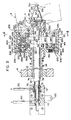
- the tubular inlet leads 34 are formed as hollow tubes 70 and 72, each of which forms an electrical connection for loop 30.
- An outer insulator sleeve 74 is provided on tube 70 and insulation sleeve 76 is provided between tubes 70, 72.
- Tubes 70, 72 are connected to leads 80, 82, respectively, at an input gap 90 of generally circular loop 30.
- Coolant lines 100, 102 direct coolant through tubes 70, 72 and leads 80, 82 for circulation of a coolant through loop 30.
- Electrical connections 110, 112 are connected across an appropriate power supply and are connected electrically to tubes 70, 72 for completing the electrical circuit through loop 30.
- This alternating current in practice, is radio frequency and has a power level to provide the desired heating temperature and pattern in a valve seat.
- a sleeve 150 has a stop shoulder 152 and an outwardly facing cylindrical surface 150a defining a protrusion which enters into a recess 154 of carrier 60.
- a pin 156 is forced through an opening in the outer surface of carrier 60 and into a bore within the metal sleeve 150. This pin locks sleeve 150 onto carrier 60 into a position where it can be assembled by an adhesive.
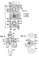
- Connections 100, 102 and 110, 112, as shown in FIGURE 3, are movable slightly to allow for this radial displacement of the floating inductor assembly with respect to the housing 20, which housing is fixed in block 14 in a radial direction with respect to axis x of assembly F.
- Thrust units 220, 222, 224, 226 are formed in pairs and are located at the diametrically opposed flange portions 142, 144 to define a relatively small transverse distance which is used for controlling the radial movement of assembly F.
- Each of the thrust units includes spaced rings 230, 232 which define facing flat surfaces between which are located a circular array of ball bearings 240. These bearings are held together by an appropriate ball retainer 234, shown in FIGURE 4.
- a cam insert 252 supports the other two rings 230 and also provides a generally conical cam recess 252a into which a cam follower assembly 260 is forced to center both flange portions 142 and 144 with respect to housing 20.
- cam follower assembly 260 includes an outer cylindrical surface to locate rings 232 onto flange 140. This function is provided by a hollow retainer 262 extending in opposite directions from flange 140 and adapted to receive an internal plunger 264 having a ball follower 266 which is forced toward cam recess 252a by an appropriate spring 268.
- Housing 20 includes an internal generally rectangular cavity 290, best shown in FIGURE 4. The periphery of this cavity is only slightly larger than the periphery of flange 140 to allow slight radial movement of the flange within the housing.
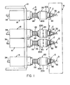
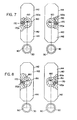
- a relatively narrow housing By providing the support arrangements in the vertical position and not in the transverse position, a relatively narrow housing can be provided. This then allows two housings to be moved close together as shown in FIGURE 1 to accommodate closely spaced valve seats in an engine component B. Also, only one design is necessary. It is not required that two floating inductor assemblies be provided, one for a right hand valve seat and the other for an adjacent left hand valve seat in a pair of seats. As shown in FIGURES 7 and 8, adjacent valve seats can be processed by reversing the position of the flange portions 142, 144. In this manner, the gaps 90 of inductor loops 30, which are on a side of assembly F, face in opposite directions, which relationship is desired in inductively heating two adjacent valve seats in a pair.
Landscapes
- Physics & Mathematics (AREA)
- Electromagnetism (AREA)
- Magnetically Actuated Valves (AREA)
Claims (9)
Priority Applications (2)
| Application Number | Priority Date | Filing Date | Title |
|---|---|---|---|
| EP19810300526 EP0057779B1 (de) | 1981-02-09 | 1981-02-09 | Schwebender Induktor für einen Ventilsitz |
| DE8181300526T DE3175646D1 (en) | 1981-02-09 | 1981-02-09 | Floating valve seat inductor |
Applications Claiming Priority (1)
| Application Number | Priority Date | Filing Date | Title |
|---|---|---|---|
| EP19810300526 EP0057779B1 (de) | 1981-02-09 | 1981-02-09 | Schwebender Induktor für einen Ventilsitz |
Publications (3)
| Publication Number | Publication Date |
|---|---|
| EP0057779A2 EP0057779A2 (de) | 1982-08-18 |
| EP0057779A3 EP0057779A3 (en) | 1983-02-16 |
| EP0057779B1 true EP0057779B1 (de) | 1986-11-20 |
Family
ID=8188208
Family Applications (1)
| Application Number | Title | Priority Date | Filing Date |
|---|---|---|---|
| EP19810300526 Expired EP0057779B1 (de) | 1981-02-09 | 1981-02-09 | Schwebender Induktor für einen Ventilsitz |
Country Status (2)
| Country | Link |
|---|---|
| EP (1) | EP0057779B1 (de) |
| DE (1) | DE3175646D1 (de) |
Family Cites Families (1)
| Publication number | Priority date | Publication date | Assignee | Title |
|---|---|---|---|---|
| USRE29046E (en) * | 1971-06-09 | 1976-11-23 | Park-Ohio Industries, Inc. | Method and apparatus for inductively heating valve seats |
-
1981
- 1981-02-09 EP EP19810300526 patent/EP0057779B1/de not_active Expired
- 1981-02-09 DE DE8181300526T patent/DE3175646D1/de not_active Expired
Also Published As
| Publication number | Publication date |
|---|---|
| EP0057779A3 (en) | 1983-02-16 |
| EP0057779A2 (de) | 1982-08-18 |
| DE3175646D1 (en) | 1987-01-08 |
Similar Documents
| Publication | Publication Date | Title |
|---|---|---|
| US4893789A (en) | Method and apparatus for hardening cam lobes on a camshaft | |
| US4449027A (en) | Electrode mounting device | |
| CN101362286B (zh) | 一种连杆衬套压装装置以及连杆衬套压装方法 | |
| US6424082B1 (en) | Apparatus and method of improved consumable alignment in material processing apparatus | |
| US4438310A (en) | Method and apparatus for inductively heating valve seat inserts | |
| US4475690A (en) | Magnetic valve, in particular a fuel injection valve | |
| US4849594A (en) | Method and apparatus for shrink fitting metal liner sleeves into inductor heated engine cylinder bores | |
| CN201261118Y (zh) | 楔形连杆衬套压装装置 | |
| US11846001B2 (en) | Split multiple coil electric induction heat treatment systems for simultaneous heating of multiple features of a bearing component | |
| US4266109A (en) | Floating valve seat inductor | |
| WO2002040221A2 (en) | Apparatus for transferring current across a robotic tool changer | |
| EP0057779B1 (de) | Schwebender Induktor für einen Ventilsitz | |
| US3743809A (en) | Method and apparatus for inductively heating valve seats | |
| USRE29046E (en) | Method and apparatus for inductively heating valve seats | |
| US4867810A (en) | Method and apparatus for hardening cam lobes on a camshaft | |
| US4673784A (en) | Valve seat inductor and method of using same | |
| CN219107703U (zh) | 一种半导体处理设备及其感应加热器 | |
| US3777096A (en) | Apparatus for inductively heating valve seats | |
| US3547797A (en) | Apparatus for simultaneously electrochemically machining a plurality of previously formed surfaces of a workpiece | |
| US4745251A (en) | Valve seat inductor | |
| US3696224A (en) | Transformer & inductor unit for heating valve seats | |
| US2898430A (en) | Induction heating devices | |
| US3970813A (en) | Apparatus for inductively heating the end of an elongated workpiece | |
| EP0064367B1 (de) | Verfahren zum induktiven Erhitzen von Ventilsitzeinlagen | |
| CA1177903A (en) | Method and apparatus for inductively heating valve seat inserts |
Legal Events
| Date | Code | Title | Description |
|---|---|---|---|
| PUAI | Public reference made under article 153(3) epc to a published international application that has entered the european phase |
Free format text: ORIGINAL CODE: 0009012 |
|
| 17P | Request for examination filed |
Effective date: 19811027 |
|
| AK | Designated contracting states |
Designated state(s): DE FR GB IT NL SE |
|
| PUAL | Search report despatched |
Free format text: ORIGINAL CODE: 0009013 |
|
| AK | Designated contracting states |
Designated state(s): DE FR GB IT NL SE |
|
| GRAA | (expected) grant |
Free format text: ORIGINAL CODE: 0009210 |
|
| ITF | It: translation for a ep patent filed | ||
| AK | Designated contracting states |
Kind code of ref document: B1 Designated state(s): DE FR GB IT NL SE |
|
| ET | Fr: translation filed | ||
| REF | Corresponds to: |
Ref document number: 3175646 Country of ref document: DE Date of ref document: 19870108 |
|
| PG25 | Lapsed in a contracting state [announced via postgrant information from national office to epo] |
Ref country code: SE Effective date: 19870210 |
|
| PG25 | Lapsed in a contracting state [announced via postgrant information from national office to epo] |
Ref country code: NL Effective date: 19870901 |
|
| PLBE | No opposition filed within time limit |
Free format text: ORIGINAL CODE: 0009261 |
|
| STAA | Information on the status of an ep patent application or granted ep patent |
Free format text: STATUS: NO OPPOSITION FILED WITHIN TIME LIMIT |
|
| NLV4 | Nl: lapsed or anulled due to non-payment of the annual fee | ||
| 26N | No opposition filed | ||
| ITTA | It: last paid annual fee | ||
| PGFP | Annual fee paid to national office [announced via postgrant information from national office to epo] |
Ref country code: GB Payment date: 19930201 Year of fee payment: 13 |
|
| PGFP | Annual fee paid to national office [announced via postgrant information from national office to epo] |
Ref country code: FR Payment date: 19930209 Year of fee payment: 13 |
|
| PGFP | Annual fee paid to national office [announced via postgrant information from national office to epo] |
Ref country code: DE Payment date: 19930224 Year of fee payment: 13 |
|
| PG25 | Lapsed in a contracting state [announced via postgrant information from national office to epo] |
Ref country code: GB Effective date: 19940209 |
|
| GBPC | Gb: european patent ceased through non-payment of renewal fee |
Effective date: 19940209 |
|
| PG25 | Lapsed in a contracting state [announced via postgrant information from national office to epo] |
Ref country code: FR Effective date: 19941031 |
|
| PG25 | Lapsed in a contracting state [announced via postgrant information from national office to epo] |
Ref country code: DE Effective date: 19941101 |
|
| REG | Reference to a national code |
Ref country code: FR Ref legal event code: ST |
|
| EUG | Se: european patent has lapsed |
Ref document number: 81300526.1 Effective date: 19880215 |