EP0057779A2 - Inducteur suspendu pour siège de soupape - Google Patents
Inducteur suspendu pour siège de soupape Download PDFInfo
- Publication number
- EP0057779A2 EP0057779A2 EP81300526A EP81300526A EP0057779A2 EP 0057779 A2 EP0057779 A2 EP 0057779A2 EP 81300526 A EP81300526 A EP 81300526A EP 81300526 A EP81300526 A EP 81300526A EP 0057779 A2 EP0057779 A2 EP 0057779A2
- Authority
- EP
- European Patent Office
- Prior art keywords
- inductor
- flange
- carrier
- movable element
- assembly
- Prior art date
- Legal status (The legal status is an assumption and is not a legal conclusion. Google has not performed a legal analysis and makes no representation as to the accuracy of the status listed.)
- Granted
Links
- 238000010438 heat treatment Methods 0.000 claims abstract description 34
- 230000008878 coupling Effects 0.000 claims abstract description 25
- 238000010168 coupling process Methods 0.000 claims abstract description 25
- 238000005859 coupling reaction Methods 0.000 claims abstract description 25
- 230000006872 improvement Effects 0.000 claims description 17
- 230000000712 assembly Effects 0.000 description 17
- 238000000429 assembly Methods 0.000 description 17
- 210000001331 nose Anatomy 0.000 description 12
- 238000010791 quenching Methods 0.000 description 5
- 230000009471 action Effects 0.000 description 4
- 238000006073 displacement reaction Methods 0.000 description 4
- 238000004519 manufacturing process Methods 0.000 description 4
- 239000002826 coolant Substances 0.000 description 3
- 230000000171 quenching effect Effects 0.000 description 3
- 239000000969 carrier Substances 0.000 description 2
- 238000002485 combustion reaction Methods 0.000 description 2
- 238000013461 design Methods 0.000 description 2
- 230000006698 induction Effects 0.000 description 2
- 239000002184 metal Substances 0.000 description 2
- 238000012545 processing Methods 0.000 description 2
- 239000000853 adhesive Substances 0.000 description 1
- 230000001070 adhesive effect Effects 0.000 description 1
- 238000013459 approach Methods 0.000 description 1
- 230000008901 benefit Effects 0.000 description 1
- 239000004020 conductor Substances 0.000 description 1
- 238000001816 cooling Methods 0.000 description 1
- 230000002939 deleterious effect Effects 0.000 description 1
- 210000003128 head Anatomy 0.000 description 1
- BHEPBYXIRTUNPN-UHFFFAOYSA-N hydridophosphorus(.) (triplet) Chemical compound [PH] BHEPBYXIRTUNPN-UHFFFAOYSA-N 0.000 description 1
- 238000010348 incorporation Methods 0.000 description 1
- 238000003780 insertion Methods 0.000 description 1
- 230000037431 insertion Effects 0.000 description 1
- 239000011810 insulating material Substances 0.000 description 1
- 238000009413 insulation Methods 0.000 description 1
- 239000012774 insulation material Substances 0.000 description 1
- 239000012212 insulator Substances 0.000 description 1
- 239000007788 liquid Substances 0.000 description 1
- 230000001050 lubricating effect Effects 0.000 description 1
- 239000000463 material Substances 0.000 description 1
- 230000007246 mechanism Effects 0.000 description 1
- 238000000034 method Methods 0.000 description 1
- 230000002093 peripheral effect Effects 0.000 description 1
- 230000008569 process Effects 0.000 description 1
Images

Classifications
-
- H—ELECTRICITY
- H05—ELECTRIC TECHNIQUES NOT OTHERWISE PROVIDED FOR
- H05B—ELECTRIC HEATING; ELECTRIC LIGHT SOURCES NOT OTHERWISE PROVIDED FOR; CIRCUIT ARRANGEMENTS FOR ELECTRIC LIGHT SOURCES, IN GENERAL
- H05B6/00—Heating by electric, magnetic or electromagnetic fields
- H05B6/02—Induction heating
- H05B6/10—Induction heating apparatus, other than furnaces, for specific applications
- H05B6/101—Induction heating apparatus, other than furnaces, for specific applications for local heating of metal pieces
Definitions
- This invention relates to the art of inductively heating valve seats and more particularly to a floating valve seat inductor assembly to be used in inductively heating valve seats.
- a floating valve seat inductor of the general type to which the present invention is directed is disclosed and claimed in prior United States Patent No. Re 29,046. This patent is incorporated by reference herein.
- valve seats have a better wear characteristic and can withstand the constant pounding by a poppet valve. This is needed because the lubricating effect of lead and phosphorous in the gasoline being consumed is no longer available.
- Several concepts have been used in providing such hardened valve seats. One of these is to utilize hardened inserts to define the valve seats themselves. Of course, this solution presents obvious difficulties in that the valve seats are more expensive and require substantially more manufacturing and assembling costs.
- the most common approach is to inductively heat the conical surface forming the valve seat of an internal combustion engine by positioning an inductor adjacent the seat and directing high frequency currents through the inductor.
- valve seat is quenched, generally by mass quenching which results from conduction of heat from the valve seat rapidly into the surrounding metal. In high production, it is desirable to heat all valve seats at the same time for subsequent quench hardening by liquid or mass cooling.
- United States Reissue Patent No. 29,046 illustrates a machine for inductively heating several valve seats simultaneously.
- a plurality of floating inductor assemblies are provided in a plurality of housings which are movable toward and away from respective valve seats of an engine component.
- Each of the inductor assemblies includes an inductor loop at one end of a carrier and a nose concentric with the loop extending toward the valve seat. This nose contacts the valve bore in the engine component to center the respective inductor carriers with respect to the valve seat preparatory to induction heating. This action occurs when the housings carrying the respective inductor assemblies are moved toward the valve seats.
- each of the inductor assemblies is centered with respect to the particular valve seat to be heated, irrespective of certain manufacturing tolerances between adjacent valve seats.
- each of the inductor assemblies floats within their respective housings in a manner to allow movement only in the radial direction.
- a flange is provided around the inductor carrier of the inductor assembly. This flange is clamped within a companion housing to allow only radial movement.
- the inductor at the end of the inductor assembly is properly positioned in the radial direction and in the axial direction for the desired heating of the valve seats.
- the present invention relates to an improvement in the floating inductor assembly of the type shown in prior United States Letters Patent No. Re 29,046, which invention overcomes the disadvantages experienced when the valve seats to be inductively heated for subsequent quenching are relatively close together.
- the floating inductor assembly of the type described above is provided with an elongated flange having two spaced flange portions, each of which is clamped in the movable member.
- This movable member forms a housing for the floating inductor assembly.
- the surrounding housing for the inductor assembly can be generally rectangular in cross-section with a dimension in the lateral direction substantially less than the dimension in the vertical direction.
- two such housings can be closely spaced with respect to each other in a transverse direction. This allows use of the concept of a floating valve seat inductor assembly when the valve seats are closely spaced.
- the housing for the inductor assembly has an internal cavity which is larger than the flange in all directions so that the flange can move within the housing in any direction radially of the inductor.
- the valve seat inductor assembly is provided with an arrangement for adjusting the angular position of its elongated flange with respect to the inductor loop located at the end of the assembly.
- the inductor loop includes a circumferentially located gap which allows current to flow in a path around the loop. This gap should not be opposite to an area of the valve seat adjacent a high mass portion of the engine component.
- a structure for adjusting the angular position of the gap forming the inductor loop.
- the needed gap can be located on either transverse side of the supporting housing according to which flange portion is extended upwardly.
- This ability to shift the gap from one side of the assembly.to the other by reversing the assembly position together with the ability to adjust slightly the specific angular position of the gap gives wide latitude in positioning the gap or space in the loop with respect to the circumference of a valve seat being hardened.
- a novel floating inductor assembly as previously described which floating inductor assembly includes an arrangement for adjusting the position of the input gap in the inductor loop with respect to the housing which carries the inductor assembly.
- the present invention relates to an improvement in the combination of the floating inductor assembly and housing for supporting the same in a machine, wherein the housing is moved toward the valve seat into a heating position and away from the valve seat into a loading position.
- the mounting means between the assembly and the housing includes first and second flange portions supported on the inductor assembly carrier. These flange portions extend radially outwardly in a direction generally perpendicular to the axis of movement of the housing toward and away from the valve seat.
- first coupling means for coupling the first flange portion onto the movable housing and a second coupling means for coupling the second flange portion onto the movable housing.
- first and second coupling means are generally in diametrically opposed relationship with respect to the moving axis of the housing and the inductor assembly carried thereby.
- Radial movement of the floating inductor assembly with respect to its housing is accomplished by including an arrangement in the coupling means for allowing only radial movement of the flange portions with respect to the housing.
- the housing may have a lateral dimension substantially less than the vertical dimension when the two spaced coupling means are vertically aligned on opposite sides of the inductor carrier.
- the housings are relatively narrow in a vertical direction with the two spaced coupling means allowing radial displacement being vertically above and vertically below the moving axis for the assembly.
- Adjacent housings can thus be close together without requiring geometrical shapes for each of two closely adjacent housings. Consequently, even though the valve seats are closely spaced with respect to each other, all valve seats can be inductively heated in a single cycle by using the present invention and without using a special configuration for each of the two closely adjacent assemblies.
- the primary object of the present invention is the provision of a floating inductor assembly for use in inductively heating valve seats, preparatory to quench hardening the seats, which inductor assembly has a radial guiding means that reduces the required transverse dimension of the unit or housing carrying the inductor assembly.
- Another object of the present invention is the provision of a floating inductor assembly, as defined above, which assembly allows the use of a pair of floating assemblies in closely spaced transverse relationship to inductively heat adjacent valve seats simultaneously.
- Still a further object of the present invention is the provision of a floating inductor assembly, as defined above, which assembly allows simultaneous heating of adjacent valve seats in engine components for use with relatively small engines wherein the spacing between the valve seats is relatively small.
- Another object of the present invention is the provision of a floating inductor assembly, as defined above, which assembly allows easy coupling with a supporting housing used to move the assembly into and from the heating position.
- a further object of the invention is the provision of a floating inductor assembly movable by a housing or other support element toward and away from a valve seat, which inductor assembly includes an inductor loop generally concentric to both the valve seat and the body of the assembly and which can be used for any of several different valve seats in an engine component.
- Yet another object of the present invention is the provision of the combination of a floating inductor assembly and a housing therefor, which combination has a relatively small transverse dimension when compared to the vertical dimension. These dimensions are controlled by the geometry of the coupling structure used to couple the inductor assembly in a radial floating manner on the movable housing.
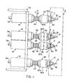
- FIGURES 1 and 2 show a machine or apparatus A which coacts with an engine component B supported opposite thereto for inductively heating the generally conical valve seats C of the engine component.
- each of the valve seats has a concentric bore D into which the stem of a poppet valve fits during operation of the engine. Since the present invention relates to an improvement in the apparatus described in United States Letters Patent R e 29,046, which patent is incorporated by reference herein, machine or apparatus A will be described only briefly.
- This apparatus includes a frame 10 movable on a base 12 and adapted to carry a plurality of locking and journal blocks 14 so that the blocks move in unison with frame 10 as it is reciprocated between the heating and loading positions.
- a housing or movable element 20 Extending outwardly from each block 14 there is provided a housing or movable element 20 supported onto a tube 22 which is slidably received within a block 14.
- the block includes a locking arrangement for locking tubes 22 with respect to blocks 14 and, thus, frame 10 when desired.
- a coil spring 24 which bias housings 20 outwardly from blocks 14 toward engine component B. In accordance with known practice, the amount of outward movement of housing 20 is restricted by structure within the blocks 14 which is not shown.
- each housing 20 there is a floating inductor assembly F having an outwardly facing inductor loop 30 with an outwardly extending centering nose member 32. Extending in the opposite direction are tubular inlet leads 34 which will be described in more detail and which are also shown in the prior United States Letters Patent.
- Inductor loop 30 is adapted to be energized when adjacent a valve seat C for the purpose of inductively heating the valve seat. After inductor loop 30 is de-energized, the mass surrounding the valve seat quenches the valve seat to harden the conical surface thereof. This increases the wear characteristics of the valve seat.
- housings 20 are aligned with respective valve seats C of engine component B, as shown in FIGURE 1.
- Frame 10 is moved into a retracted position, generally shown in FIGURE 2A, and springs 24 force housings 20 in a forward or extended direction to a position which will allow loading of an engine component B in front of machine A.
- FIGURE 2B frame 10 is moved toward engine component B. This moves all of the locking and journal blocks 14 carrying housings 20 which are reciprocally mounted on the blocks.
- inductor loop 30 is centered with respect to valve seat C.
- frame 10 moves further in the forward direction until all of the inductor loops engage their respective valve seats. This is also shown in FIGURE 2 B .
- springs 24 allow proper positioning of the inductor loops in contact with the respective valve seats.
- locking blocks 14 lock all tubes 22 with respect to the blocks and, thus, with respect to common frame 10.
- frame 10 is retracted, as shown in FIGURE 2C, a distance corresponding to the desired air gap between the inductor loops and the valve seats.
- the present invention relates to an improvement in a mechanism for mounting assembly F in housing 20 and for allowing this radial movement of floating inductor assembly F with respect to the housing.
- a device constructed in accordance with the invention does not require a substantial transverse dimension. for housing 20.
- the transverse dimension means a dimension in a direction extending between the valve seats as shown in FIGURE l.
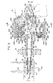
- a carrier 60 machined from an insulating material includes a forwardly facing recess 62 into which is adhesively secured a plug 64 also formed from an insulation material.
- Inductor loop 30 is a hollow conductor and is held between plug 64 and carrier 60.
- Carrier 60 includes an outwardly facing conical portion onto the end of which is mounted the previously discussed centering nose member 32.
- This member has an enlarged support shoulder 32a abutting the end of plug 64, a cylindrical body portion 32b, which is concentric with axis x, and a tapered point 32c which allows insertion of nose member 32,into bore D.
- the tubular inlet leads 34 are formed as hollow tubes 70 and 72, each of which forms an electrical connection for loop 30.
- An outer insulator sleeve 74 is provided on tube 70 and insulation sleeve 76 is provided between tubes 70, 72.
- Tubes 70, 72 are connected to leads 80, 82, respectively, at an input gap 90 of generally circular loop 30.
- Coolant lines 100, 102 direct coolant through tubes 70, 72 and leads 80, 82 for circulation of a coolant through loop 30.
- E lec- trical connections 110, 112 are connected across an appropriate power supply and are connected electrically to tubes 70, 72 for completing the electrical circuit through loop 30.
- alternating current is directed through loop 30.
- This alternating current in practice, is radio frequency and has a power level to provide the desired heating temperature and pattern in a valve seat.
- a sleeve 150 has a stop shoulder 152 and an outwardly facing cylindrical surface l50a defining a protrusion which enters into a recess 154 of carrier 60.
- a pin 156 is forced through an opening in the outer surface of carrier 60 and into a bore within the metal sleeve 150. This pin locks sleeve 150 onto carrier 60 into a position where it can be assembled by an adhesive.
- Flange 140 includes a central cylindrical bore 160 surrounding surface 152a and fixedly held to sleeve 150 by a set screw 170 having an inwardly directed pin 170a. This pin is adapted to enter one of several angularly spaced bores 180 in sleeve 150. Any number of bores could be provided; however, three bores are illustrated. In this manner, the relative position of the flange portions 142, 144 with respect to loop 30 can be adjusted slightly for a purpose to be explained in more detail with respect to FIGURES 7 and 8. Rectangular flange 140 is assembled onto and becomes a part. of the floating inductor assembly F by the structure so far explained.
- Rectangular flange 140 is supported within housing 20 by spaced rectangular plates 200, 202 between which extends a rectangular wall 204. Peripheral bolts 206 clamp plates 200, 202 together to capture flange portions 142, 144 within housing 20.
- the coupling between housing 20 and floating inductor assembly F allows only radial movement between these two assembled components.
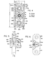
- thrust units 220, 222, 224 and 226 are provided which firmly grip flange portions 142, 144 in a manner to allow only radial displacement of the total inductor assembly F with respect to the housing 20, which housing is reciprocated to and from the valve seat as previously described.
- Connections 100, 102 and 110, 112, as shown in FIGURE 3, are movable slightly to allow for this radial displacement of the floating inductor assembly with respect to the housing 20, which housing is fixed in block 14 in a radial direction with respect to axis x of assembly F.
- Thrust units 220, 222, 224,.226 are formed in pairs and are located at the diametrically opposed flange portions 142, 144 to define a relatively small transverse distance which is used for controlling the radial movement of assembly F.
- Each of the thrust units includes spaced rings 230, 232 which define facing flat surfaces between which are located a circular array of ball bearings 240. These bearings are held together by an appropriate ball retainer 234, shown in FIGURE 4.
- a cam insert 252 supports the other two rings 230 and also provides a generally conical cam recess 252a into which a cam follower assembly 260 is forced to center both flange portions 142 and 144 with respect to housing 20.
- cam follower assembly 260 includes an outer cylindrical surface to locate rings 232 onto flange 140. This function is provided by a hollow retainer 262 extending in opposite directions from flange 140 and adapted to receive an internal plunger 264 having a ball follower 266 which is forced toward cam recess 2 5 2a by an appropriate spring 268.
- insert 252 has a threaded shank 252b received in plate 200.
- Set screw 270 locks the insert in a position adjusted by an Allen wrench in recess 252c.
- a clearance opening 272 is provided at the forward end of housing 20 to allow slight radial movement of inductor assembly F during the centering action.
- An appropriate 0 -ring seal 280 is provided around the clearance opening to prevent ingress of deleterious material into the interior of housing or movable element 20.
- Housing 20 includes an internal generally rectangular cavity 290, best shown in FIGURE 4. The periphery of this cavity is only slightly larger than the periphery of flange 140 to allow slight radial movement of the flange within the housing.
- diametrically opposed flange portions 142, 144 allows support of floating inductor assembly F without requiring a relatively large transverse dimension b for housing 20.
- This dimension is dictated primarily by the transverse width a of the thrust units 222-226 and the width of flange portions 142, 144 needed to coact with these units.
- This dimension a is substantially less than the vertical height c of housing 20.
- the thickness or transverse dimension b is less than 7.5 cm when the height of housing 20 is greater than 10 cm.
- the clearance in cavity 290 for flange 140 is such that balls 240 stay on their supporting rings and the cam and followers on portions 142, 144 remain in active engagement. This dimension is selected to accommodate the largest axial misalignment of a valve seat with an assembly F.
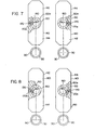
- a relatively narrow housing By providing the support arrangements in the vertical position and not in the transverse position, a relatively narrow housing can be provided. This then allows two housings to be moved close together as shown in FIGURE 1 to accommodate closely spaced valve seats in an engine component B. Also, only one design is necessary. It is not required that two floating inductor assemblies be provided, one for a right hand valve seat and the other for an adjacent left hand valve seat in a pair of seats. As shown in FIGURES 7 and 8, adjacent valve seats can be processed by reversing the position of the flange portions 142, 144. In this manner, the gaps 90 of inductor loops 30, which are on a side of assembly F, face in opposite directions, which relationship is desired in inductively heating two adjacent valve seats in a pair.
- gaps 90 can be adjusted slightly with respect to the vertical position of flange 140. In this manner, the gaps can be moved to desired circumferential positions in a valve seat being heated during set up of the machine A.
- a right and left heating unit can be created only by inventing assembly F in its housing 20. Thereafter, slight angular adjustments can be made by turning flange 140 on carrier 60.
Landscapes
- Physics & Mathematics (AREA)
- Electromagnetism (AREA)
- Magnetically Actuated Valves (AREA)
Priority Applications (2)
| Application Number | Priority Date | Filing Date | Title |
|---|---|---|---|
| EP19810300526 EP0057779B1 (fr) | 1981-02-09 | 1981-02-09 | Inducteur suspendu pour siège de soupape |
| DE8181300526T DE3175646D1 (en) | 1981-02-09 | 1981-02-09 | Floating valve seat inductor |
Applications Claiming Priority (1)
| Application Number | Priority Date | Filing Date | Title |
|---|---|---|---|
| EP19810300526 EP0057779B1 (fr) | 1981-02-09 | 1981-02-09 | Inducteur suspendu pour siège de soupape |
Publications (3)
| Publication Number | Publication Date |
|---|---|
| EP0057779A2 true EP0057779A2 (fr) | 1982-08-18 |
| EP0057779A3 EP0057779A3 (en) | 1983-02-16 |
| EP0057779B1 EP0057779B1 (fr) | 1986-11-20 |
Family
ID=8188208
Family Applications (1)
| Application Number | Title | Priority Date | Filing Date |
|---|---|---|---|
| EP19810300526 Expired EP0057779B1 (fr) | 1981-02-09 | 1981-02-09 | Inducteur suspendu pour siège de soupape |
Country Status (2)
| Country | Link |
|---|---|
| EP (1) | EP0057779B1 (fr) |
| DE (1) | DE3175646D1 (fr) |
Family Cites Families (1)
| Publication number | Priority date | Publication date | Assignee | Title |
|---|---|---|---|---|
| USRE29046E (en) * | 1971-06-09 | 1976-11-23 | Park-Ohio Industries, Inc. | Method and apparatus for inductively heating valve seats |
-
1981
- 1981-02-09 DE DE8181300526T patent/DE3175646D1/de not_active Expired
- 1981-02-09 EP EP19810300526 patent/EP0057779B1/fr not_active Expired
Also Published As
| Publication number | Publication date |
|---|---|
| EP0057779B1 (fr) | 1986-11-20 |
| EP0057779A3 (en) | 1983-02-16 |
| DE3175646D1 (en) | 1987-01-08 |
Similar Documents
| Publication | Publication Date | Title |
|---|---|---|
| US4893789A (en) | Method and apparatus for hardening cam lobes on a camshaft | |
| US4449027A (en) | Electrode mounting device | |
| US4438310A (en) | Method and apparatus for inductively heating valve seat inserts | |
| US7009478B2 (en) | Solenoid arrangement | |
| US4849594A (en) | Method and apparatus for shrink fitting metal liner sleeves into inductor heated engine cylinder bores | |
| US11846001B2 (en) | Split multiple coil electric induction heat treatment systems for simultaneous heating of multiple features of a bearing component | |
| US4266109A (en) | Floating valve seat inductor | |
| JPS5818969B2 (ja) | レ−スリングの転動面を誘導加熱する方法及び装置 | |
| USRE29046E (en) | Method and apparatus for inductively heating valve seats | |
| US3743809A (en) | Method and apparatus for inductively heating valve seats | |
| US4542272A (en) | Induction heating device with electronic positioning control | |
| US4867810A (en) | Method and apparatus for hardening cam lobes on a camshaft | |
| EP0057779B1 (fr) | Inducteur suspendu pour siège de soupape | |
| US4673784A (en) | Valve seat inductor and method of using same | |
| US3696224A (en) | Transformer & inductor unit for heating valve seats | |
| US3761669A (en) | Method and apparatus for inductively heating valve seats | |
| US3777096A (en) | Apparatus for inductively heating valve seats | |
| US4745251A (en) | Valve seat inductor | |
| US2898430A (en) | Induction heating devices | |
| CA1187142A (fr) | Methode de chauffage par induction des garnitures pour sieges de soupapes | |
| EP0041317A1 (fr) | Procédé et appareillage pour le chauffage par induction de sièges de soupape en vue de la trempe de la surface de siège | |
| US2281333A (en) | Progressive heat treating apparatus | |
| US2288041A (en) | Induction heat-treating apparatus | |
| US4659892A (en) | Valve seat induction heating apparatus | |
| US20060124632A1 (en) | Induction Heating Device With Electromagnetic Diverter |
Legal Events
| Date | Code | Title | Description |
|---|---|---|---|
| PUAI | Public reference made under article 153(3) epc to a published international application that has entered the european phase |
Free format text: ORIGINAL CODE: 0009012 |
|
| 17P | Request for examination filed |
Effective date: 19811027 |
|
| AK | Designated contracting states |
Designated state(s): DE FR GB IT NL SE |
|
| PUAL | Search report despatched |
Free format text: ORIGINAL CODE: 0009013 |
|
| AK | Designated contracting states |
Designated state(s): DE FR GB IT NL SE |
|
| GRAA | (expected) grant |
Free format text: ORIGINAL CODE: 0009210 |
|
| ITF | It: translation for a ep patent filed | ||
| AK | Designated contracting states |
Kind code of ref document: B1 Designated state(s): DE FR GB IT NL SE |
|
| ET | Fr: translation filed | ||
| REF | Corresponds to: |
Ref document number: 3175646 Country of ref document: DE Date of ref document: 19870108 |
|
| PG25 | Lapsed in a contracting state [announced via postgrant information from national office to epo] |
Ref country code: SE Effective date: 19870210 |
|
| PG25 | Lapsed in a contracting state [announced via postgrant information from national office to epo] |
Ref country code: NL Effective date: 19870901 |
|
| PLBE | No opposition filed within time limit |
Free format text: ORIGINAL CODE: 0009261 |
|
| STAA | Information on the status of an ep patent application or granted ep patent |
Free format text: STATUS: NO OPPOSITION FILED WITHIN TIME LIMIT |
|
| NLV4 | Nl: lapsed or anulled due to non-payment of the annual fee | ||
| 26N | No opposition filed | ||
| ITTA | It: last paid annual fee | ||
| PGFP | Annual fee paid to national office [announced via postgrant information from national office to epo] |
Ref country code: GB Payment date: 19930201 Year of fee payment: 13 |
|
| PGFP | Annual fee paid to national office [announced via postgrant information from national office to epo] |
Ref country code: FR Payment date: 19930209 Year of fee payment: 13 |
|
| PGFP | Annual fee paid to national office [announced via postgrant information from national office to epo] |
Ref country code: DE Payment date: 19930224 Year of fee payment: 13 |
|
| PG25 | Lapsed in a contracting state [announced via postgrant information from national office to epo] |
Ref country code: GB Effective date: 19940209 |
|
| GBPC | Gb: european patent ceased through non-payment of renewal fee |
Effective date: 19940209 |
|
| PG25 | Lapsed in a contracting state [announced via postgrant information from national office to epo] |
Ref country code: FR Effective date: 19941031 |
|
| PG25 | Lapsed in a contracting state [announced via postgrant information from national office to epo] |
Ref country code: DE Effective date: 19941101 |
|
| REG | Reference to a national code |
Ref country code: FR Ref legal event code: ST |
|
| EUG | Se: european patent has lapsed |
Ref document number: 81300526.1 Effective date: 19880215 |