EP0057746B1 - Heat flux limiting sleeves - Google Patents
Heat flux limiting sleeves Download PDFInfo
- Publication number
- EP0057746B1 EP0057746B1 EP81107817A EP81107817A EP0057746B1 EP 0057746 B1 EP0057746 B1 EP 0057746B1 EP 81107817 A EP81107817 A EP 81107817A EP 81107817 A EP81107817 A EP 81107817A EP 0057746 B1 EP0057746 B1 EP 0057746B1
- Authority
- EP
- European Patent Office
- Prior art keywords
- heat flux
- tube
- flux limiting
- sleeve
- limiting device
- Prior art date
- Legal status (The legal status is an assumption and is not a legal conclusion. Google has not performed a legal analysis and makes no representation as to the accuracy of the status listed.)
- Expired
Links
Images
Classifications
-
- F—MECHANICAL ENGINEERING; LIGHTING; HEATING; WEAPONS; BLASTING
- F28—HEAT EXCHANGE IN GENERAL
- F28F—DETAILS OF HEAT-EXCHANGE AND HEAT-TRANSFER APPARATUS, OF GENERAL APPLICATION
- F28F13/00—Arrangements for modifying heat-transfer, e.g. increasing, decreasing
- F28F13/14—Arrangements for modifying heat-transfer, e.g. increasing, decreasing by endowing the walls of conduits with zones of different degrees of conduction of heat
-
- F—MECHANICAL ENGINEERING; LIGHTING; HEATING; WEAPONS; BLASTING
- F22—STEAM GENERATION
- F22B—METHODS OF STEAM GENERATION; STEAM BOILERS
- F22B1/00—Methods of steam generation characterised by form of heating method
- F22B1/02—Methods of steam generation characterised by form of heating method by exploitation of the heat content of hot heat carriers
- F22B1/06—Methods of steam generation characterised by form of heating method by exploitation of the heat content of hot heat carriers the heat carrier being molten; Use of molten metal, e.g. zinc, as heat transfer medium
- F22B1/063—Methods of steam generation characterised by form of heating method by exploitation of the heat content of hot heat carriers the heat carrier being molten; Use of molten metal, e.g. zinc, as heat transfer medium for metal cooled nuclear reactors
Definitions
- This invention relates to heat exchanger tubes and more particularly to heat flux limiting sleeves for heat exchanger tubes.
- the present invention resides in a heat flux limiting device for a heat exchanger tube, comprising a sleeve extending over a portion of said tube and varying in diameter along the length thereof depending on the heat transfer rate at the tube surface so as to limit the heat transfer rate through the sleeve and tube to a predetermined value, characterized in that said sleeve comprises a plurality of cylindrical portions of different diameters.
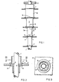
- FIG. 1 there is shown a portion of a heat exchanger tube 1 over which a heat flux limiting sleeve 3 is disposed adjacent an upper tubesheet 5.
- the sleeve 3 is larger in diameter on one end, the upper end, than it is on the other end, the lower end.
- An outwardly extending flange 7 is disposed adjacent the upper end of the sleeve 3 and supports the sleeve 3 on one of several support plates 9 disposed along the length of the sleeve 3.
- the sleeve 3 consists of a plurality of generally cylindrical portions 3a graduated in diameter, the upper cylindrical portions 3a being larger in diameter than the lower cylindrical portions 3a.
- Figs. 2 and 3 these are provided collars 11, which are disposed between adjacent cylindrical portions 3a.
- the collars 11 allow for axial expansion between adjacent cylindrical portions 3a and are counterbored from each end to receive the respective cylindrical portions 3a.
- a land 13 is disposed between the counterbores and has grooves 15 disposed therein for the passage of fluid from one cylindrical portion to the adjacent cylindrical portion.
- the land 13 is only slightly larger in diameter than the tubes.
- Drain vent sluts 18 are provided in the cylindrical portions 3a or in the collars 11.
- the collars 11 also have an outwardly extending flange 17 disposed on the upper end thereof and the collars fit into a hole in the support plates 9. Stakes 19 as shown in Figure 3 may be provided for fastening the collar 11 in the support plates 9.
- the heat flux sleeves 3 hereinbefore described also have a wall thickness which decreases in the same direction as the diameter decreases.
- the inside diameter of the sleeves 3 may be constant, may vary in the same direction or in the opposite direction as the outside diameter to provide an effective, inexpensive, and reliable heat flux sleeve for a liquid metal steam generator.
Landscapes
- Engineering & Computer Science (AREA)
- Physics & Mathematics (AREA)
- Thermal Sciences (AREA)
- Mechanical Engineering (AREA)
- General Engineering & Computer Science (AREA)
- High Energy & Nuclear Physics (AREA)
- Life Sciences & Earth Sciences (AREA)
- Sustainable Development (AREA)
- Sustainable Energy (AREA)
- Heat-Exchange Devices With Radiators And Conduit Assemblies (AREA)
- Details Of Heat-Exchange And Heat-Transfer (AREA)
Description
- This invention relates to heat exchanger tubes and more particularly to heat flux limiting sleeves for heat exchanger tubes.
- Steam generators utilized with Liquid Metal Fast Breeder Reactors (LMFBR) and designed to produce dry saturated steam will see severe temperature differences between the hot sodium on the shell side and the boiling water within the tubes. Normally with the heat exchanger, the greater the temperature differential, the greater the effectiveness of the heat exchanger elements. However, there are material limitations since extremely high heat transfer rates can cause tube damage due to chemical concentrations and rapid temperature fluctuations, particularly at the boiling surfaces. The combination of liquid metal on the shell side and nucleate boiling within the tubes results in extremely high heat fluxes. When prestressed double walled tubes are utilized in LMFBR steam generators, the temperature differential across the double walled tubes may be sufficient to produce separation at the interface of the walls.
- It is known from French patent application No. 2,097,056 to surround heat exchanger tubes with heat transfer limiting sleeves including tapered structures which provide for varying heat transfer rates so as to cause about the same amount of heat to be transferred at one end where there is a relatively large temperature difference as on the other end with a relatively low temperature difference for even heat transmission in a cross-flow heat exchanger for example. These structures however are mounted directly on the tubes in some areas and spaced from the tubes in other areas and therefore will produce localized heat transfer rate differences which could cause severe damages to tubes which are operated near the limit of the temperature gradient acceptable for the material of which the tubes consist.
- It is therefore the principal object of the present invention to provide some means for the safe protection of tubes, which operate near high temperature gradients, especially in the highest heat transfer area.
- With this object in view, the present invention resides in a heat flux limiting device for a heat exchanger tube, comprising a sleeve extending over a portion of said tube and varying in diameter along the length thereof depending on the heat transfer rate at the tube surface so as to limit the heat transfer rate through the sleeve and tube to a predetermined value, characterized in that said sleeve comprises a plurality of cylindrical portions of different diameters.
- The invention will become more readily apparent from the following description of a preferred embodiment thereof shown by way of example only in the accompanying drawings, in which:
- Figure 1 is a partial elevational view of a heat exchanger tube with a heat flux limiting sleeve made in accordance with this invention;
- Figure 2 is an enlarged partial sectional view taken on line II-II of Figure 1; and
- Figure 3 is a sectional view taken on line III-III of Figure 2.
- Referring now to the drawings in detail and in particular to Figure 1, there is shown a portion of a heat exchanger tube 1 over which a heat
flux limiting sleeve 3 is disposed adjacent anupper tubesheet 5. Thesleeve 3 is larger in diameter on one end, the upper end, than it is on the other end, the lower end. - An outwardly extending flange 7 is disposed adjacent the upper end of the
sleeve 3 and supports thesleeve 3 on one of several support plates 9 disposed along the length of thesleeve 3. - In accordance with the invention, the
sleeve 3 consists of a plurality of generally cylindrical portions 3a graduated in diameter, the upper cylindrical portions 3a being larger in diameter than the lower cylindrical portions 3a. - According to Figs. 2 and 3 these are provided collars 11, which are disposed between adjacent cylindrical portions 3a. The collars 11 allow for axial expansion between adjacent cylindrical portions 3a and are counterbored from each end to receive the respective cylindrical portions 3a. A
land 13 is disposed between the counterbores and hasgrooves 15 disposed therein for the passage of fluid from one cylindrical portion to the adjacent cylindrical portion. Theland 13 is only slightly larger in diameter than the tubes.Drain vent sluts 18 are provided in the cylindrical portions 3a or in the collars 11. The collars 11 also have an outwardly extendingflange 17 disposed on the upper end thereof and the collars fit into a hole in the support plates 9. Stakes 19 as shown in Figure 3 may be provided for fastening the collar 11 in the support plates 9. - The
heat flux sleeves 3 hereinbefore described also have a wall thickness which decreases in the same direction as the diameter decreases. The inside diameter of thesleeves 3 may be constant, may vary in the same direction or in the opposite direction as the outside diameter to provide an effective, inexpensive, and reliable heat flux sleeve for a liquid metal steam generator.
Claims (5)
Applications Claiming Priority (2)
| Application Number | Priority Date | Filing Date | Title |
|---|---|---|---|
| US06/230,554 US4537249A (en) | 1981-02-02 | 1981-02-02 | Heat flux limiting sleeves |
| US230554 | 1981-02-02 |
Publications (2)
| Publication Number | Publication Date |
|---|---|
| EP0057746A1 EP0057746A1 (en) | 1982-08-18 |
| EP0057746B1 true EP0057746B1 (en) | 1984-08-29 |
Family
ID=22865653
Family Applications (1)
| Application Number | Title | Priority Date | Filing Date |
|---|---|---|---|
| EP81107817A Expired EP0057746B1 (en) | 1981-02-02 | 1981-10-01 | Heat flux limiting sleeves |
Country Status (4)
| Country | Link |
|---|---|
| US (1) | US4537249A (en) |
| EP (1) | EP0057746B1 (en) |
| JP (1) | JPS57134696A (en) |
| DE (1) | DE3165783D1 (en) |
Families Citing this family (10)
| Publication number | Priority date | Publication date | Assignee | Title |
|---|---|---|---|---|
| US4619314A (en) * | 1983-08-05 | 1986-10-28 | Ishikawajima-Harima Jukogyo Kabushiki Kaisha | Device for preventing wear of heat transfer tubes in fluidized-bed boiler |
| US4529123A (en) * | 1983-09-02 | 1985-07-16 | Combustion Research Corporation | Radiant heater system |
| DE3706645A1 (en) * | 1987-03-02 | 1988-09-15 | Doerhoefer Dofa Kessel Und App | Heat exchanger |
| DE3715713C1 (en) * | 1987-05-12 | 1988-07-21 | Borsig Gmbh | Heat exchanger in particular for cooling cracked gases |
| NL194891C (en) * | 1993-11-24 | 2003-06-04 | Lentjes Standard Fasel Bv | Cooling device for cooling a warm medium. |
| DE19645390C2 (en) * | 1996-11-04 | 2000-01-13 | Metallgesellschaft Ag | Medium or high pressure heat exchanger with a heat-insulating cladding |
| EP1304159A1 (en) * | 2001-10-19 | 2003-04-23 | Methanol Casale S.A. | Method and reactor for carrying out chemical reactions in pseudo-isothermal conditions |
| DE102008018931A1 (en) | 2007-04-17 | 2008-11-13 | Gyrus ACMI, Inc., Southborough | Light source power based on a predetermined detected condition |
| JP2012516980A (en) | 2009-02-04 | 2012-07-26 | パーデュ リサーチ ファンデーション | Heat exchanger for metal hydride storage system |
| JP2012516984A (en) * | 2009-02-04 | 2012-07-26 | パーデュ リサーチ ファンデーション | Bladed heat exchanger for metal hydride storage system |
Family Cites Families (13)
| Publication number | Priority date | Publication date | Assignee | Title |
|---|---|---|---|---|
| US1762467A (en) * | 1928-01-13 | 1930-06-10 | Metalcraft Heater Corp | Automobile heater and the silencing of automobile heaters |
| US2315792A (en) * | 1941-04-21 | 1943-04-06 | Arthur B Hoss | Adapter |
| US2420373A (en) * | 1944-09-15 | 1947-05-13 | Us Steel Corp Of Delaware | Hot-blast stove |
| US3132691A (en) * | 1959-02-06 | 1964-05-12 | Babcock & Wilcox Co | Heat exchanger construction and thermal shield therefor |
| CH398763A (en) * | 1963-02-21 | 1966-03-15 | Bbc Brown Boveri & Cie | Magnetogas dynamic generator with cooled duct walls |
| GB1225967A (en) * | 1967-03-22 | 1971-03-24 | ||
| NL6807673A (en) * | 1968-05-30 | 1969-12-02 | ||
| BE760718A (en) * | 1970-01-22 | 1971-05-27 | Babcock Atlantique Sa | STEAM GENERATORS IMPROVEMENTS |
| FR2097056B1 (en) * | 1970-07-30 | 1974-09-20 | Chausson Usines Sa | |
| US3743252A (en) * | 1972-03-16 | 1973-07-03 | Gloucester Eng Co Inc | Air cooled extruder |
| GB1431785A (en) * | 1972-12-22 | 1976-04-14 | Atomic Energy Authority Uk | Heat exchangers |
| US3982901A (en) * | 1975-06-25 | 1976-09-28 | Dorr-Oliver Incorporated | Heat transfer element and tuyere for fluidized bed reactor |
| SU821897A1 (en) * | 1979-06-25 | 1981-04-15 | Новополоцкий политехнический институт | Tube-in-tube heat exchanging element |
-
1981
- 1981-02-02 US US06/230,554 patent/US4537249A/en not_active Expired - Fee Related
- 1981-10-01 DE DE8181107817T patent/DE3165783D1/en not_active Expired
- 1981-10-01 EP EP81107817A patent/EP0057746B1/en not_active Expired
- 1981-10-01 JP JP56154932A patent/JPS57134696A/en active Pending
Also Published As
| Publication number | Publication date |
|---|---|
| EP0057746A1 (en) | 1982-08-18 |
| DE3165783D1 (en) | 1984-10-04 |
| JPS57134696A (en) | 1982-08-19 |
| US4537249A (en) | 1985-08-27 |
Similar Documents
| Publication | Publication Date | Title |
|---|---|---|
| EP0015510B1 (en) | Device to reduce local heat flux through a heat exchanger tube | |
| US4909316A (en) | Dual-tube heat pipe type heat exchanger | |
| EP0057746B1 (en) | Heat flux limiting sleeves | |
| EP0013796A1 (en) | Heat exchanger with leak detecting double wall tubes | |
| CA1245120A (en) | Steam generator tube support | |
| JPS6037389B2 (en) | liquid distributor | |
| GB1140533A (en) | Liquid-metal cooled nuclear reactors | |
| US4226283A (en) | Multitubular heat exchanger | |
| US4157114A (en) | Tubesheet with a thermal sleeve | |
| GB969036A (en) | Improvements in or relating to tubular heat exchange apparatus | |
| US3130780A (en) | Live steam reheater | |
| GB1262377A (en) | Heat exchanger for production of steam | |
| US3251404A (en) | Liquid metal heated steam generator | |
| GB1220867A (en) | Tubular heat exchange assembly | |
| JPH076754B2 (en) | Heat exchanger | |
| US3176761A (en) | Heat exchanger | |
| JPS59112197A (en) | Heat exchanger | |
| SU1177653A1 (en) | Heat tube | |
| JPS5553698A (en) | Finned tube type heat exchanger | |
| SU1193426A1 (en) | Gravity thermal tube | |
| FR2287668A1 (en) | Shell-side shroud with short sleeve for each tube - protects tube to tube-sheet joint against high gradient | |
| Linning | Tube in shell heat exchangers | |
| SU819554A1 (en) | Heat exchanger element | |
| JPS5541362A (en) | Heat exchanger | |
| Linning | Improvements in or relating to heat exchangers |
Legal Events
| Date | Code | Title | Description |
|---|---|---|---|
| PUAI | Public reference made under article 153(3) epc to a published international application that has entered the european phase |
Free format text: ORIGINAL CODE: 0009012 |
|
| AK | Designated contracting states |
Designated state(s): BE DE FR GB NL |
|
| 17P | Request for examination filed |
Effective date: 19830202 |
|
| GRAA | (expected) grant |
Free format text: ORIGINAL CODE: 0009210 |
|
| PGFP | Annual fee paid to national office [announced via postgrant information from national office to epo] |
Ref country code: DE Payment date: 19840821 Year of fee payment: 4 |
|
| AK | Designated contracting states |
Designated state(s): BE DE FR GB NL |
|
| PGFP | Annual fee paid to national office [announced via postgrant information from national office to epo] |
Ref country code: FR Payment date: 19840925 Year of fee payment: 4 |
|
| PGFP | Annual fee paid to national office [announced via postgrant information from national office to epo] |
Ref country code: BE Payment date: 19840930 Year of fee payment: 4 |
|
| REF | Corresponds to: |
Ref document number: 3165783 Country of ref document: DE Date of ref document: 19841004 |
|
| ET | Fr: translation filed | ||
| PLBE | No opposition filed within time limit |
Free format text: ORIGINAL CODE: 0009261 |
|
| STAA | Information on the status of an ep patent application or granted ep patent |
Free format text: STATUS: NO OPPOSITION FILED WITHIN TIME LIMIT |
|
| 26N | No opposition filed | ||
| PGFP | Annual fee paid to national office [announced via postgrant information from national office to epo] |
Ref country code: NL Payment date: 19871031 Year of fee payment: 7 |
|
| PG25 | Lapsed in a contracting state [announced via postgrant information from national office to epo] |
Ref country code: GB Effective date: 19881001 |
|
| PG25 | Lapsed in a contracting state [announced via postgrant information from national office to epo] |
Ref country code: BE Effective date: 19881031 |
|
| BERE | Be: lapsed |
Owner name: WESTINGHOUSE ELECTRIC CORP. Effective date: 19881031 |
|
| PG25 | Lapsed in a contracting state [announced via postgrant information from national office to epo] |
Ref country code: NL Effective date: 19890501 |
|
| NLV4 | Nl: lapsed or anulled due to non-payment of the annual fee | ||
| PG25 | Lapsed in a contracting state [announced via postgrant information from national office to epo] |
Ref country code: FR Free format text: LAPSE BECAUSE OF NON-PAYMENT OF DUE FEES Effective date: 19890630 |
|
| PG25 | Lapsed in a contracting state [announced via postgrant information from national office to epo] |
Ref country code: DE Effective date: 19890701 |
|
| GBPC | Gb: european patent ceased through non-payment of renewal fee | ||
| REG | Reference to a national code |
Ref country code: FR Ref legal event code: ST |