EP0057657B1 - Automatic, fluid tight coupling - Google Patents
Automatic, fluid tight coupling Download PDFInfo
- Publication number
- EP0057657B1 EP0057657B1 EP82630011A EP82630011A EP0057657B1 EP 0057657 B1 EP0057657 B1 EP 0057657B1 EP 82630011 A EP82630011 A EP 82630011A EP 82630011 A EP82630011 A EP 82630011A EP 0057657 B1 EP0057657 B1 EP 0057657B1
- Authority
- EP
- European Patent Office
- Prior art keywords
- coupling
- fluid
- segment
- port
- segments
- Prior art date
- Legal status (The legal status is an assumption and is not a legal conclusion. Google has not performed a legal analysis and makes no representation as to the accuracy of the status listed.)
- Expired
Links
- 230000008878 coupling Effects 0.000 title claims description 137
- 238000010168 coupling process Methods 0.000 title claims description 137
- 238000005859 coupling reaction Methods 0.000 title claims description 137
- 239000012530 fluid Substances 0.000 title claims description 114
- 239000000523 sample Substances 0.000 claims description 8
- 238000004891 communication Methods 0.000 claims description 5
- 238000003780 insertion Methods 0.000 claims description 2
- 230000037431 insertion Effects 0.000 claims description 2
- 230000000295 complement effect Effects 0.000 claims 1
- 239000007789 gas Substances 0.000 description 10
- 238000012360 testing method Methods 0.000 description 7
- 239000002699 waste material Substances 0.000 description 7
- 239000000463 material Substances 0.000 description 6
- 230000007423 decrease Effects 0.000 description 4
- 229910001018 Cast iron Inorganic materials 0.000 description 3
- 238000004519 manufacturing process Methods 0.000 description 3
- 238000011084 recovery Methods 0.000 description 3
- 238000002485 combustion reaction Methods 0.000 description 2
- 238000011109 contamination Methods 0.000 description 2
- 238000006073 displacement reaction Methods 0.000 description 2
- 230000007246 mechanism Effects 0.000 description 2
- 230000003068 static effect Effects 0.000 description 2
- 230000001133 acceleration Effects 0.000 description 1
- 239000003518 caustics Substances 0.000 description 1
- 239000000470 constituent Substances 0.000 description 1
- 239000000356 contaminant Substances 0.000 description 1
- 230000001419 dependent effect Effects 0.000 description 1
- 230000006866 deterioration Effects 0.000 description 1
- 230000009977 dual effect Effects 0.000 description 1
- 230000000694 effects Effects 0.000 description 1
- 230000002708 enhancing effect Effects 0.000 description 1
- 238000007667 floating Methods 0.000 description 1
- 239000000446 fuel Substances 0.000 description 1
- 239000007788 liquid Substances 0.000 description 1
- 230000013011 mating Effects 0.000 description 1
- 238000005259 measurement Methods 0.000 description 1
- 238000000034 method Methods 0.000 description 1
- 239000004033 plastic Substances 0.000 description 1
- 229920003023 plastic Polymers 0.000 description 1
- 238000007789 sealing Methods 0.000 description 1
- 238000010998 test method Methods 0.000 description 1
- 238000012546 transfer Methods 0.000 description 1
Images

Classifications
-
- F—MECHANICAL ENGINEERING; LIGHTING; HEATING; WEAPONS; BLASTING
- F16—ENGINEERING ELEMENTS AND UNITS; GENERAL MEASURES FOR PRODUCING AND MAINTAINING EFFECTIVE FUNCTIONING OF MACHINES OR INSTALLATIONS; THERMAL INSULATION IN GENERAL
- F16L—PIPES; JOINTS OR FITTINGS FOR PIPES; SUPPORTS FOR PIPES, CABLES OR PROTECTIVE TUBING; MEANS FOR THERMAL INSULATION IN GENERAL
- F16L25/00—Construction or details of pipe joints not provided for in, or of interest apart from, groups F16L13/00 - F16L23/00
- F16L25/0018—Abutment joints
-
- F—MECHANICAL ENGINEERING; LIGHTING; HEATING; WEAPONS; BLASTING
- F16—ENGINEERING ELEMENTS AND UNITS; GENERAL MEASURES FOR PRODUCING AND MAINTAINING EFFECTIVE FUNCTIONING OF MACHINES OR INSTALLATIONS; THERMAL INSULATION IN GENERAL
- F16L—PIPES; JOINTS OR FITTINGS FOR PIPES; SUPPORTS FOR PIPES, CABLES OR PROTECTIVE TUBING; MEANS FOR THERMAL INSULATION IN GENERAL
- F16L37/00—Couplings of the quick-acting type
- F16L37/58—Couplings of the quick-acting type the extremities of the two halves of the joint being pressed against each other without being locked in position
Definitions
- This invention relates to a fluid coupling for transporting fluid through an ambient pressure environment between fluid sources, comprising first and second segments, each comprising a fluid carrying aperture with a major diameter mounting port at one end and a minor diameter coupling port at a coupling end thereof, said mounting ports each adapted for fluid communication with a fluid source, said first segment coupling port disposed in an end wall of a cylindrical cavity in said first segment coupling end and said second segment coupling port disposed in an end wall of a cylindrical probe in said second segment coupling end, said probe being adapted for releasably engaging said cavity in coupling of said coupling ends to provide registration of said coupling ports at a coupling interface to form a venturi comprised of the fluid carrying apertures of the coupled segments, said engaged coupling ports forming the throat of said venturi.
- a coupling of this type is known from US-A-3,009,716.
- Fluid couplings are used to convey a fluid between fluid sources without leakage to the surrounding ambient.
- the fluid may be either liquid or gas, and the couplings either permanent (semipermanent) or temporary.
- the permanent type couplings are fixedly engaged and must be assembled and disassembled by hand.
- the temporary couplings are those in which the engagement is only for short intervals, such as the time required to complete the ftuid transfer. While these temporary couplings may also be assembled and disassembled manually they typically include some type of automatic engagement and release coupling interface.
- US-A-3,009,716 is an example of the prior art "active" couplings using hermetic seals and mechanical latching means.
- US-A-3,009,716 is concerned with a coupling for a gaseously pressurized fluid tank.
- the gas pressure in the tank being adapted to be increased for forcing fuel out of the tank.
- a venturi throat is provided at the junction of the coupling segments.
- the internal space of the coupling surrounding the interface of the coupling segments is in communication with the interior of the tank and a pressure is built up in said internal space which is greater than the reduced pressure at the venturi throat and greater than the ambient pressure.
- This increased pressure avoids leakage of the fluid to be transported and is sealed with respect to the surrounding atmosphere by a hermetic seal.
- an active mechanical connection provided between the two coupling segments.
- the object of the present invention is to provide a fluid coupling with passive, automatic engagement and release and which does not require a hermetic fluid seal.
- the fluid coupling of the invention is characterized in that each of said minor diameters are selected to provide an aperture fluid pressure at said coupling interface which is not greater than the outside ambient pressure, thereby preventing fluid escape therefrom.
- the automatic fluid coupling of the present invention provides a fluid tight connection for conveying fluid between sources without the use of external sealing components, such as rings or gaskets for containing the fluid within the coupling.
- the probe coupling end and cavity coupling end of the two segments engage each other in a slip-fit relationship and provide a male/female type connection.
- This allows the segments to releasably engage each other by simple abutment (engage) or withdrawal (disengage) of the two segments at the interface.
- the non-hermeticity allows for the mating interface (coupling interface) to be loosely toleranced, while still providing containment of the fluid flow through the coupling.
- the loose tolerances and male/ female connection allow the coupling to be easily engaged with self alignment of the segments to permit quick engagement and release.
- the simple geometry of the coupling segments allows for ease of manufacture, at low cost. Selection of the segment material is based on the particular fluid application, e.g. causticity of the fluid and the maximum impact forces during engagement, to provide a coupling with a high degree of wearability in use, without need for replacements of wear items such as seals or gaskets.
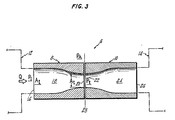
- the coupling 6 comprises dual segments, an inlet segment 8 and an outlet segment 10, for providing fluid communication between a fluid source 12 and a fluid "sink" 14 (each shown in phantom).
- a fluid source 12 a fluid "sink" 14 (each shown in phantom).
- sink defines a fluid receiver or reservoir, and as with the labels inlet and outlet for the coupling segments is intended only to infer a direction of fluid flow.
- the inlet segment 8 receives the fluid from the source at a major diameter fluid input port 16 and channels the fluid through an internal fluid carrying aperture 18 to a minor diameterfluid coupling port 20 of the inlet segment.
- the coupling port 20 When the coupling is engaged, the coupling port 20 is in registration with a like minor diameter coupling port 22 of the outlet segment 10, which also includes an internal fluid carrying aperture 24 in fluid communication with the coupling port 22 and a fluid output port 26 which discharges the fluid to the sink 14.
- the coupling ports 20, 22 When engaged, the coupling ports 20, 22 abut each other in registration along the coupling interface 28 to provide a non-hermetically sealed conduit through the coupling, between the input and output ports.
- either segment may receive or discharge the fluid; the two segments are interchangeable with respect to the direction of fluid flow.
- the fluid passage, or conduit through the coupling is provided by the registered central, longitudinal fluid apertures 18, 24 during engagement of the segments.
- the equal minor diameter coupling ports forming the coupling interface 28 are smaller than the diameter of the central apertures at either of the fluid input or output ports 16, 26.
- the narrow internal diameter of the coupling ports provide a restriction to the fluid flowing through the coupling.
- the fluid flow characteristics may be described by Bernoulli's equation which requires that the sum of: the instantaneous fluid pressure (P), the kinetic fluid energy (ZpV 2 ; p is fluid density and V is fluid velocity), and static fluid energy (pgy; g is gravitational acceleration and y is vertical displacement in the plane of fluid flow) must be constant along the conduit.
- P instantaneous fluid pressure
- ZpV 2 kinetic fluid energy
- pgy gravitational acceleration and y is vertical displacement in the plane of fluid flow
- the fluid received at the major diameter input port 16, which has a cross-sectional area A, includes a volumetric flow rate (Q) and fluid velocity ( ⁇ ) at the input port.
- the fluid velocity increases along the aperture as the internal cross-sectional area decreases (converging diameter) in the region of the restriction at the coupling interface 28 to a value A i .
- This resembles a Venturi flow, with the restriction provided by the minor diameter coupling ports (20, 22) defining the throat of the Venturi.
- the fluid velocity at the throat (v t ) is greater than the velocity at the input port ( VI ) in direct proportion to the ratio of the cross-sectional areas
- the pressure differential between the fluid at the input port (P,) and the coupling interface (P t ), i.e. ⁇ P P 1 -P t , is equal to Since the fluid velocity at any point along the conduit may be expressed as the ratio of the volumetric flow (Q) divided by the instant cross-sectional area (A), then The cross-sectional area of the throat may then be defined in terms of AP, the input cross-sectional area (A,), the volumetric flow (Q), and the fluid density (p), or:
- the minor diameter value of the coupling ports 20, 22 is selected with respect to the major diameter value of the input port 16, so that the smaller cross-sectional area (At) which produces the increased fluid velocity at the coupling interface, also provides a maximum fluid pressure at the interface which is not greater than (equal to or less than) the ambient pressure surrounding the outside of the coupling.
- At cross-sectional area
- the fluid in the coupling may, however, be contaminated by entrainment of ambient fluid which is sucked into the internal aperture whenever the internal fluid pressure is less than the ambient pressure.
- the present coupling finds the highest utility in the transport of waste fluid from a source to a waste fluid disposal unit. In particular the ability to contain waste fluid without the need for a sealed interface which makes the present coupling particularly well suited for automated fluid waste disposal applications.
- One such application is the safe evacuation of exhaust gas from an internal combustion (IC) engine to some type of central exhaust evacuation system.
- IC internal combustion
- the engines are automatically shuttled from a production line into automated test cells, where they are connected in a combined automatic/manual procedure to the various engine services, exhaust discharge, and sensor connections.
- the present coupling allows automatic connection of the engine exhaust discharge to the central exhaust system. With present hot-test procedures having total test times of less than ten minutes the savings in time provided by an automatic exhaust connection is significant.
- an automatic coupling 30 has inlet and outlet segments 32, 34.
- the outlet segment 34 is fitted through a portion of the bulkhead 36 of the engine test cell enclosure, in a semifixed manner, by mounting the segment through a bulkhead aperture 38 having an internal diameter greater than the outer diameter of the segment. This allows the segment to "float" in its mounting with 360° of radial freedom. The radial motion allows for self-aligning of the outlet segment coupling port with the inlet segment coupling port during engagement.
- the segment is held in axial position in the bulkhead by mounting collars 40, 42 disposed on the outside surface of the segment; the bulkhead section being assembled in two halves around the segment body, between the collars.
- the coupling output or mounting port 44 (14, Fig. 3) is connected through a suitable conduit, such as a flexible hose 46 to the central exhaust system.
- the input segment 32 includes a mounting flange 48 for rigidly fixing (mounting) the segment to the particular fluid source, e.g. engine exhaust manifold to provide registration of the fluid input or mounting port 50 with the discharge from the manifold.
- the rigid mounting of the inlet segment and floating mount of the outlet segment allow the two to self align during engagement, which is provided by steering the engine on a conveyor apparatus into the test cell; the coupling being engaged by the placement of the engine adjacent the bulkhead 36 and disengaged by withdrawal of the engine from the cell.
- the ends of the segments which engage each other i.e. the ends 52, 54 which form the coupling interface, are provided with a male/female type connection.
- This allows the segments to releasably engage each other in a slip-fit fashion in which the two segments are maintained in spatial proximity with the coupling end 52 of the inlet segment 32 abutting the coupling end 54 of the outlet segment 34 as a result of the physical placement of the engine adjacent the bulkhead.
- the coupling port 58 of the output segment 34 is disposed in an end wall 62 of a female cylindrical cavity 61 at the output segment coupling end 54 and the coupling port 56 of the input segment 32 is disposed in an end wall of a cylindrical male probe 65 at the coupling end 52 of the input segment 32.
- the outlet segment 34 includes a complimentary chamfer 66 along the sidewall 60.
- the preferred coupling embodiment includes a cylindrical outer surface geometry for the two segments; this further enhancing the ability of the two segments to automatically engage each other.
- the coupling material is whatever is deemed suitable for the particular fluid application, i.e. that suitable for conveying the particular fluid without deterioration of the coupling due to any caustic elements contaminants in the fluid.
- the segment material is preferably a high quality cast iron, having a low thermal coefficient of expansion to limit changes in tolerance fit due to the discharge temperatures of the gas.
- the cast iron allows for minimizing the coupling damage (especially the outlet segment 34) due to repeated engagement cycles; this particular coupling application results in a significant impact force between the segments during each coupling event.
- the cast iron is capable of withstanding the corrosive effects of the exhaust gas constituents.
- the particular type of material is dependent on the particular fluid application in which the coupling is used. In those applications where the fluid itself is noncaustic, or the application does not require repeated engagement/disengagement of the coupling so as to require high strength material lesser strength materials may be used, such as plastics.
- the internal geometry of the fluid carrying aperture of the inlet segment (the converging cross-sectional area) is in the form of a Venturi tube, it need not have the fine converging taper of a Venturi tube which typically has an inlet converging taper in the shape of a Bellmouth designed with carefully rounded shoulders to eliminate fluid resistance and produce high aerodynamic efficiency.
- the converging taper is simply a piece-wise linear taper, i.e. no discontinuities. Since the coupling application is that of waste fluid transport, fluid pressure recovery downstream of the restricted throat portion is not of concern.
- the converging portion and diverging portion (inlet/ outlet) of a Venturi differ in length; the diverging portion taper is typically five times greater than that of the inlet or converging portion. This again is to allow for pressure recovery. This may also be provided in the present coupling, if pressure recovery is of concern, otherwise the two sections are substantially the same length.
- the coupling port minor diameter value required to produce a fluid pressure at the coupling interface which is equal to, or less than ambient pressure an example is given based on the application of the coupling as an exhaust gas conduit for an IC engine.
- the engine is assumed to have three cylinders, 2500 cm 3 displacement, and an exhaust discharge port having a 3,81 cm outer diameter.
- the engine rated back pressure is 0,1035 kg/cm 2 at a rated engine speed (test measurement speed) of 3000 RPM.
- the volumetric flow at ambient temperature is
- P t the throat
- P A ambient
- coupling tolerances, ambient changes, and additional friction head losses have not been considered in example, but would be taken into account in a given application to ensure a maximum P, value which is not greater than P A .
Landscapes
- Engineering & Computer Science (AREA)
- General Engineering & Computer Science (AREA)
- Mechanical Engineering (AREA)
- Quick-Acting Or Multi-Walled Pipe Joints (AREA)
- Testing Of Engines (AREA)
- Flanged Joints, Insulating Joints, And Other Joints (AREA)
Applications Claiming Priority (2)
| Application Number | Priority Date | Filing Date | Title |
|---|---|---|---|
| US231540 | 1981-02-04 | ||
| US06/231,540 US4452277A (en) | 1981-02-04 | 1981-02-04 | Automatic, fluid tight coupling |
Publications (2)
| Publication Number | Publication Date |
|---|---|
| EP0057657A1 EP0057657A1 (en) | 1982-08-11 |
| EP0057657B1 true EP0057657B1 (en) | 1985-11-13 |
Family
ID=22869663
Family Applications (1)
| Application Number | Title | Priority Date | Filing Date |
|---|---|---|---|
| EP82630011A Expired EP0057657B1 (en) | 1981-02-04 | 1982-02-03 | Automatic, fluid tight coupling |
Country Status (6)
| Country | Link |
|---|---|
| US (1) | US4452277A (es) |
| EP (1) | EP0057657B1 (es) |
| JP (1) | JPS57146986A (es) |
| DE (1) | DE3267342D1 (es) |
| ES (1) | ES509287A0 (es) |
| IE (1) | IE52466B1 (es) |
Families Citing this family (14)
| Publication number | Priority date | Publication date | Assignee | Title |
|---|---|---|---|---|
| DE3149537C2 (de) * | 1981-12-15 | 1986-07-24 | Hochtemperatur-Reaktorbau GmbH, 4600 Dortmund | Doppelrohrleitung mit Wirkdruckmeßstelle |
| JPS6110741A (ja) * | 1984-06-26 | 1986-01-18 | Horiba Ltd | サンプリング配管 |
| US4923222A (en) * | 1988-04-25 | 1990-05-08 | Deshazer William A | Casing sealing apparatus |
| US5931664A (en) * | 1997-04-21 | 1999-08-03 | General Kinematics Corporation | Non-mechanical leak-proof coupling |
| US5988943A (en) * | 1997-09-18 | 1999-11-23 | Mccord; Brent | Liquid distribution device for drainfields |
| US6698455B2 (en) * | 2002-03-20 | 2004-03-02 | Pablo Alvaro Ramirez-Rivera | Fluid multieconomizer device |
| DE102007056922A1 (de) * | 2007-11-27 | 2009-05-28 | BSH Bosch und Siemens Hausgeräte GmbH | Wasserführendes Hausgerät mit einer Wasserweiche |
| DE102007056921A1 (de) * | 2007-11-27 | 2009-05-28 | BSH Bosch und Siemens Hausgeräte GmbH | Wasserführendes Haushaltsgerät mit einer Wasserweiche |
| DE102007057336A1 (de) * | 2007-11-28 | 2009-06-04 | BSH Bosch und Siemens Hausgeräte GmbH | Wasserführendes Haushaltsgerät mit einer Wasserweiche |
| US7810401B2 (en) * | 2008-03-07 | 2010-10-12 | Cameron International Corporation | Apparatus and method for operation in the laminar, transition, and turbulent flow regimes |
| GB2462412B (en) * | 2008-08-04 | 2011-01-05 | Rolls Royce Plc | A flow control arrangement |
| GB2480667A (en) * | 2010-05-27 | 2011-11-30 | Rob Pond Agencies Ltd | Fluid flow control device |
| US10024479B2 (en) * | 2012-03-15 | 2018-07-17 | James M Henderson | System and method for providing upkeep and maintenance to piping systems |
| US20220388229A1 (en) * | 2021-06-07 | 2022-12-08 | Sanctuary Cognitive Systems Corporation | Tapered hydraulic hose, methods of making, and applications thereof in robot systems |
Citations (2)
| Publication number | Priority date | Publication date | Assignee | Title |
|---|---|---|---|---|
| US1305668A (en) * | 1919-06-03 | Walter n | ||
| US3009716A (en) * | 1958-12-02 | 1961-11-21 | Gen Dynamics Corp | Venturi coupling apparatus |
Family Cites Families (9)
| Publication number | Priority date | Publication date | Assignee | Title |
|---|---|---|---|---|
| US535642A (en) * | 1895-03-12 | Proportional water-meter | ||
| US2095899A (en) * | 1934-03-27 | 1937-10-12 | J C Nicklos | Bottom hole choke |
| GB651622A (en) * | 1948-10-11 | 1951-04-04 | British Insulated Callenders | Improvements relating to sealing glands |
| US2712458A (en) * | 1950-06-05 | 1955-07-05 | Lipson Leonard | Pipe couplings |
| US2842962A (en) * | 1953-10-29 | 1958-07-15 | Kent Ltd G | Pressure differential producing device |
| US3018799A (en) * | 1958-02-20 | 1962-01-30 | Willy B Volkmann | Water surge arrester |
| US3226505A (en) * | 1962-11-09 | 1965-12-28 | Luther R Lucas | Fluid flow interlock |
| GB1342994A (en) * | 1972-07-24 | 1974-01-10 | Clarke Chapman John Thompson L | Equalising flow in pipes |
| NL175457C (nl) * | 1978-02-21 | 1984-11-01 | Wavin Bv | Trekvaste buisverbinding, alsmede hiervoor geschikt verbindingsorgaan. |
-
1981
- 1981-02-04 US US06/231,540 patent/US4452277A/en not_active Expired - Fee Related
-
1982
- 1982-02-01 IE IE214/82A patent/IE52466B1/en unknown
- 1982-02-03 ES ES509287A patent/ES509287A0/es active Granted
- 1982-02-03 EP EP82630011A patent/EP0057657B1/en not_active Expired
- 1982-02-03 DE DE8282630011T patent/DE3267342D1/de not_active Expired
- 1982-02-04 JP JP57016932A patent/JPS57146986A/ja active Pending
Patent Citations (2)
| Publication number | Priority date | Publication date | Assignee | Title |
|---|---|---|---|---|
| US1305668A (en) * | 1919-06-03 | Walter n | ||
| US3009716A (en) * | 1958-12-02 | 1961-11-21 | Gen Dynamics Corp | Venturi coupling apparatus |
Also Published As
| Publication number | Publication date |
|---|---|
| DE3267342D1 (en) | 1985-12-19 |
| ES8302223A1 (es) | 1982-12-16 |
| US4452277A (en) | 1984-06-05 |
| EP0057657A1 (en) | 1982-08-11 |
| JPS57146986A (en) | 1982-09-10 |
| ES509287A0 (es) | 1982-12-16 |
| IE820214L (en) | 1982-08-04 |
| IE52466B1 (en) | 1987-11-11 |
Similar Documents
| Publication | Publication Date | Title |
|---|---|---|
| EP0057657B1 (en) | Automatic, fluid tight coupling | |
| EP2053294B1 (en) | Boot shrouds for joints in conduits | |
| US2753195A (en) | Self-sealing coupling | |
| US3679237A (en) | Coupling for joining glass pipe sections and the like | |
| EP1613888B1 (en) | Coupling assembly | |
| FI72810C (fi) | Anordning foer ledning av vaetsketryck till en differentialtryckomvandlare. | |
| US5407237A (en) | Flexible coupling | |
| JPS6146654B2 (es) | ||
| US4921258A (en) | Adapter seal | |
| US3695637A (en) | Inflatable coupling | |
| US4094520A (en) | Self centering flange gasket assembly | |
| EP0096475A3 (en) | Improvements in staple couplings | |
| WO1996018091A1 (en) | Manifold for use with a pressure transmitter | |
| JPS61180091A (ja) | 自動閉塞継手 | |
| US4886301A (en) | Quick disconnect with a position compensating seal | |
| CN114251524A (zh) | 双壁流体运输系统和相关方法 | |
| EP1863560B1 (en) | Device and method for contamination-free and/or sterile sealing between at least two interconnectable connecting means | |
| US2905486A (en) | Coupling device | |
| GB2263145A (en) | Fluid couplings and seals | |
| US9157824B2 (en) | High pressure fluid coupling | |
| EP4086496A1 (en) | Transfer tube assembly | |
| US12312068B2 (en) | Transmission system | |
| BR0214144A (pt) | Dispositivo de acoplamento para condutos de fluido de pressão e um método para fabricação de tal acoplamento, compreendendo uma fenda de vazamento para indicação de vazamento | |
| EP4506607A1 (en) | Systems and methods for conveying gas and twist-lock connectors for the same | |
| CN114725425B (zh) | 燃料电池发动机进气歧管及燃料电池发动机 |
Legal Events
| Date | Code | Title | Description |
|---|---|---|---|
| PUAI | Public reference made under article 153(3) epc to a published international application that has entered the european phase |
Free format text: ORIGINAL CODE: 0009012 |
|
| AK | Designated contracting states |
Designated state(s): DE FR GB |
|
| 17P | Request for examination filed |
Effective date: 19830112 |
|
| GRAA | (expected) grant |
Free format text: ORIGINAL CODE: 0009210 |
|
| AK | Designated contracting states |
Designated state(s): DE FR GB |
|
| ET | Fr: translation filed | ||
| REF | Corresponds to: |
Ref document number: 3267342 Country of ref document: DE Date of ref document: 19851219 |
|
| PLBE | No opposition filed within time limit |
Free format text: ORIGINAL CODE: 0009261 |
|
| STAA | Information on the status of an ep patent application or granted ep patent |
Free format text: STATUS: NO OPPOSITION FILED WITHIN TIME LIMIT |
|
| 26N | No opposition filed | ||
| PGFP | Annual fee paid to national office [announced via postgrant information from national office to epo] |
Ref country code: FR Payment date: 19910114 Year of fee payment: 10 |
|
| PGFP | Annual fee paid to national office [announced via postgrant information from national office to epo] |
Ref country code: GB Payment date: 19910116 Year of fee payment: 10 |
|
| PGFP | Annual fee paid to national office [announced via postgrant information from national office to epo] |
Ref country code: DE Payment date: 19910129 Year of fee payment: 10 |
|
| PG25 | Lapsed in a contracting state [announced via postgrant information from national office to epo] |
Ref country code: GB Effective date: 19920203 |
|
| GBPC | Gb: european patent ceased through non-payment of renewal fee | ||
| PG25 | Lapsed in a contracting state [announced via postgrant information from national office to epo] |
Ref country code: FR Effective date: 19921030 |
|
| PG25 | Lapsed in a contracting state [announced via postgrant information from national office to epo] |
Ref country code: DE Effective date: 19921103 |
|
| REG | Reference to a national code |
Ref country code: FR Ref legal event code: ST |